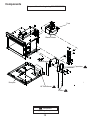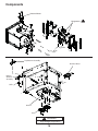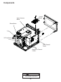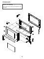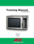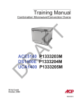
1
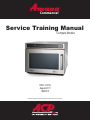
R Commercial Service Training Manual Compact Models HDC - 60 Hz August 2011 16400011 Amana® is a Registered Trademark of Maytag Corporation. Brand used under license. Table of Contents Important Safety Information.........................................................................................2-5 Quick Start Reference Guide......................................................................................9-10 ! "####$% &' ! "#(##)* ! "#(##)(&'( &+ ,) /3% 4( / 46 3((() 7363($# 1 Important Safety Information 1 Important Information Important Notices for Servicers and Consumers ACP will not be responsible for personal injury or property damage from improper service procedures. Pride and workmanship go into every product to provide our customers with quality products. It is possible, however, that during its lifetime a product may require service. Products should be serviced only by a qualified service technician who is familiar with the safety procedures required in the repair and who is equipped with the proper tools, parts, testing instruments and the appropriate service information. IT IS THE TECHNICIANS RESPONSIBLITY TO REVIEW ALL APPROPRIATE SERVICE INFORMATION BEFORE BEGINNING REPAIRS. ! WARNING To avoid risk of severe personal injury or death, disconnect power before working/servicing on appliance to avoid electrical shock. To locate an authorized servicer please contact: ComServ Support Center Web Site WWW.ACPSOLUTIONS.COM ....................... Telephone Number 1-866-426-2621 or 319-368-8195 E-Mail: [email protected] Recognize Safety Symbols, Words, and Labels ! DANGER DANGER— Immediate hazards which WILL result in severe personal injury or death. ! WARNING WARNING— Hazards or unsafe practices which COULD result in severe personal injury or death. ! CAUTION CAUTION— Hazards or unsafe practices which COULD result in minor personal injury, product or property damage. 2 Important Safety Information ! WARNING Read the following information to avoid possible exposure to microwave radiation: The basic design of the Microwave Oven makes it an inherently safe device to both use and service. However, there are some precautions which should be followed when servicing the microwave to maintain this safety. These are as follows: 1. Always operate the unit from an adequately grounded outlet. Do not operate on a two-wire extension cord. 8. Do not for any reason defeat the interlock switches there is not valid reason for this action at any time; nor will it be condoned by ACP. 2. Before servicing the unit (if unit is operable) perform the microwave leakage test. 9. IMPORTANT: Before returning a unit to a customer, be sure to check for proper switch interlock action. 3. The oven should never be operated if the door does not fit properly against the seal, the hinges or hinge bearings are damaged or broken; the choke is damaged, (pieces missing, etc.); or any other visible damage can be noted. Check the choke area to ensure that this area is clean and free of all foreign matter. 10. The Microwave Oven should never be operated with any components removed and/or bypassed or when any of the safety interlocks are found to be defective, or when any of the seal surfaces are defective, missing, or damaged. 11. All microwave ovens meet all requirements of the radiation control for Health and Safety Act of 1968. Due to measurement uncertainties, the maximum leakage for the field will be 4mw/cm2. 4. If the oven operates with the door open and produces microwave energy, take the following steps: A. Tell the user not to operate the oven. B. Contact ACP ComServ immediately. 12. To ensure that the unit does not emit excessive microwave leakage and to meet the Department of Health and Human Services guidelines, check the oven for microwave leakage using a microwave oven leakage meter that complies with US Government CDRH / FDA / DHHS requirements and or any other local government requirements. The maximum leakage level allowed by ACP 2 is 4mw/cm . 5. Always have the oven disconnected when the outer case is removed except when making the "live" tests called for in the Service Manual. Do not reach into the equipment area while the unit is energized. Make all connections for the test and check them for tightness before plugging the cord into the outlet. 6. Always ground the capacitors on the magnetron filter box with an insulated-handle screwdriver before working in the high voltage area of the equipment compartment. Some types of failures will leave a charge in these capacitors and the discharge could cause a reflex action which could make you injure yourself. 13. If servicer encounters an emission reading over 4mw/cm 2, the servicer is to cease repair and contact the ACP ComServ Department immediately for further direction. ACP will contact the proper Government Agency upon verification of the test results. 7. Always remember that in the area of the transformer there is HIGH VOLTAGE. When the unit is operating keep this area clear and free of anything which could possibly cause an arc or ground, etc. 3 IMPORTANT SAFETY INSTRUCTIONS Recognize this symbol as a SAFETY message ! WARNING When using electrical equipment, basic safety precautions should be followed to reduce the risk of burns, 6 _^^ >4 436' ,3 1. READ all instructions before using equipment. 9. DO NOT heat baby bottles in oven. F*&&"HJ!!J76 “PRECAUTIONS TO AVOID POSSIBLE EXPOSURE TO EXCESSIVE MICROWAVE ENERGY” on this page. 10. Baby food jars shall be open when heated and contents stirred or shaken before consumption, in order to avoid burns. 11 DO NOT operate this equipment if it has a damaged cord or plug, if it is not working properly, or if it has been damaged or dropped. 3. This equipment MUST BE GROUNDED. Connect only to properly GROUNDED outlet. See “ GROUNDING / EARTHING INSTRUCTIONS” on page 5. 12. This equipment, including power cord, must be =J"!{@4= Special tools are required to service equipment. Contact nearest authorized service facility for examination, repair, or adjustment. 4. Install or locate this equipment ONLY in accordance with the installation instructions in this manual. 5. Some products such as whole eggs and sealed containers—for example, closed glass jars—are able to explode and SHOULD NOT be HEATED in this oven. 13. DO NOT cover or block louvers or other openings on equipment. 14. DO NOT store this equipment outdoors. DO NOT use this product near water – for example, near a kitchen sink, in a wet basement, a swimming pool, or a similar location. 6. Use this equipment ONLY for its intended use as described in this manual. Do not use corrosive chemicals or vapors in this equipment. This type ' =3 6^ _^ or dry food. It is not designed for industrial or laboratory use. 15. DO NOT immerse cord or plug in water. 16. Keep cord AWAY from HEATED surfaces. 17. DO NOT let cord hang over edge of table or counter. 7. As with any equipment, CLOSE SUPERVISION is necessary when used by CHILDREN. 18. For commercial use only. 8. See door cleaning instructions on page A-4 of this owners manual. PRECAUTIONS TO AVOID POSSIBLE EXPOSURE TO EXCESSIVE MICROWAVE ENERGY A. DO NOT attempt to operate this oven with the door open since open door operation can result in harmful exposure to microwave energy. It is important not to defeat or tamper with the safety interlocks. B. DO NOT place any object between the oven front face and the door too allow soil or cleaner residue to accumulate on sealing surfaces. C. DO NOT operate the oven if it is damaged. It is particularly important that the oven door close properly and that there is no damage to the: 1. door (bent) 2. hinges and latches (broken or loosened) 3. door seals and sealing surfaces. /6 =6 4 >4 ? @4= SAVE THESE INSTRUCTIONS 4 IMPORTANT SAFETY INSTRUCTIONS WARNING WARNING / = _ '6 == a. DO NOT overcook food. Carefully attend oven when paper, plastic, or other combustible materials are placed inside the oven to facilitate cooking. b. Remove wire twist-ties from paper or plastic bags before placing bag in oven. c. If materials inside the oven ignite, keep oven door CLOSED, turn oven off and disconnect the power cord, or shut off power at the fuse or circuit breaker panel. d. DO NOT use the cavity for storage. DO NOT leave paper products, cooking utensils, or food in the cavity when not in use. ! Liquids such as water, coffee, or tea are able to be overheated beyond the boiling point without appearing to be boiling due to surface tension of the liquid. Visible bubbling or boiling when the container is removed from the microwave oven is not always present. THIS COULD RESULT IN VERY HOT LIQUIDS SUDDENLY BOILING OVER WHEN A SPOON OR OTHER UTENSIL IS INSERTED INTO THE LIQUID. To reduce the risk of injury to persons: i) ii) Do not overheat the liquid. Stir the liquid both before and halfway through heating it. iii) Do not use straight-sided containers with narrow necks. iv) After heating, allow the container to stand in the microwave oven for a short time before removing the container. v) Use extreme care when inserting a spoon or other utensil into the container. CAUTION To avoid personal injury or property damage, observe the following: 1. Do not deep fat fry in oven. Fat could overheat and be hazardous to handle. 9. Never use paper, plastic, or other combustible materials that are not intended for cooking. 2. Do not cook or reheat eggs in shell or with an unbroken yolk using microwave energy. Pressure may build up and erupt. Pierce yolk with fork or knife before cooking. 10. When cooking with paper, plastic, or other combustible materials, follow manufacturer’s recommendations on product use. 3. Pierce skin of potatoes, tomatoes, and similar foods before cooking with microwave energy. When skin is pierced, steam escapes evenly. 4. Do not operate equipment without load or food in oven cavity. 5. Microwave popcorn should not be popped in oven. 6. Do not use regular cooking thermometers in oven. Most cooking thermometers contain mercury and may cause an electrical arc, malfunction, or damage to oven. 7. Do not use metal utensils in oven. 11. Do not use paper towels which contain nylon or 666 4 melt and cause paper to ignite. 12. Do not heat sealed containers or plastic bags in oven. Food or liquid could expand quickly and cause container or bag to break. Pierce or open container or bag before heating. 13. To avoid pacemaker malfunction, consult physician or pacemaker manufacturer about effects of microwave energy on pacemaker. 14. An authorized servicer MUST inspect equipment annually. Record all inspections and repairs for future use. 8. Do not use aluminum foil in oven SAVE THESE INSTRUCTIONS 5 2 HDC 60 Hz Specifications Power Specification · Input · Output · Consumption Oven Dimensions · Weight Installation · Unpacking the oven · Radio Interference 6 Models Power Source Voltage AC Amperage Frequency Single Phase, 3 wire grounded %43 34 Power Output Nominal microwave energy (IEC705) Minimum temperature rise Operating Frequency Power Consumption Cook Condition Microwave Dimensions Cabinet Width Height Depth Cavity Dimensions Width Height Depth Weight Crated Uncrated HDC12* HDC18* CRC18T2OG HDC21* CRC21T2RL 120V 20 A 60 Hz X NEMA 5-20 208 - 240V 20 A 60 Hz X NEMA 6-20 208 - 240V 20 A 60 Hz X NEMA 6-20 1200 W 1800 W 2100 W 12°F / 6.5°C 2450 MHz 18°F / 10°C 2450 MHz 21°F / 11.5°C 2450 MHz 2000 W, 16.8 A 3000 W@ 208v, 14.4 A 3200 W@ 208v, 15.4 A 3000W @ 240v, 12.5 A 3200 W@ 240v, 13.4 A 16¾” (425) 13½” (343) 22” (559) 16¾” (425) 13½” (343) 22” (559) 16¾” (425) 13½” (343) 22” (559) 13” (330) 6 ¾” (171) 12” (305) 13” (330) 6 ¾” (171) 12” (305) 13” (330) 6 ¾” (171) 12” (305) 73 lbs. (33 kg.) 67 lbs. (30 kg.) 73 lbs. (33 kg.) 67 lbs. (30 kg.) 73 lbs. (33 kg.) 67 lbs. (30 kg.) Installation % ^= ^' from oven. ^= ^ to obtain stronger signal reception. Unpacking Oven =' 346 dents inside oven cavity. F _3 4 '46 immediately. Do not attempt to use oven if damaged. F =' = ' =6 ? ^, few hours before connecting power. Radio Interference Microwave operation may cause interference to radio, television, or similar a oven. Reduce or eliminate interference by doing the following: 34' ' = 3 instructions in “Care and Cleaning” section. 7 3 HDC 60 Hz Quick Start Reference Guide Control Panel · Programming items Clean Filter · Settings User Options · Changing options · Factory presets 8 Quick Start Reference Guide Refer to Product Safety Manual for Safety Statements Complete Owner’s Manual available online Oven Clearances CLEAN FILTER A—For North American (UL/CSA) models, allow at least 7” (17.8 cm) of clearance around top of oven. For International (50 Hz) models, allow at least 7” (17.8 cm) of clearance around top of oven. Proper This oven displays CLEAN FILTER message displays ACP recommends properly and life of electrical parts is reduced. B—Allow at least 2 9/16” (6.5 cm) between air discharge on back of oven and back wall. C—Allow at least 7” (17.8 cm) around sides of oven. off the message. The message will stop displaying automatically after 24 hours. Depending on microwave use and environmental conditions, more frequently. Once the frequency is determined, set the option for the appropriate time frame. Preprogrammed Pads To cook food using preprogrammed cooking sequences. 1. Open oven door and place food in oven. Close door. 2. Press desired pad. 3. Oven begins to cook. 4. At end of cooking cycle oven beeps and shuts off. 2 X2 Programming (some models) To change the cooking factor: 1. Open oven door. 2. Press and hold pad 1 for approximately 5 seconds. 3. Press pad to be reprogrammed. 4. Press the X2 pad. 5. Press a numbered pad to change the cooking factor. Cooking factor can be set from 10% to 100%. Default is 80%. Pad 5 would change the cooking factor to 50%. 6. Press START pad to save changes. So...how do I use it? Time Entry Stop/Reset Manual Operation Power Level Start 1. Open oven door and place food in oven. Close door. 2. Press TIME ENTRY pad and enter cooking time. 3. Press POWER LEVEL pad to program level of microwave power if desired. For a lower microwave power, press pads 1 (for 10%), through 9 (for 90%), or 0 for no microwave energy. NOTE: Press POWER LEVEL pad once to return to 100% microwave power. 4. Press START pad. 5. At end of cooking cycle oven beeps and shuts off. Programming Items 1. 2. 3. 4. 5. Open oven door. Press and hold pad 1 for approximately 5 seconds. Press pad to be reprogrammed. Enter cooking time by using the number pads. Press POWER LEVEL pad to program level of microwave power if desired. For a lower microwave power, press pads 1 (for 10%), through 9 (for 90%), or 0 for no microwave energy. NOTE: Press POWER LEVEL pad once to return to 100% microwave power. 6. Press TIME ENTRY pad to add up to four additional cooking stages. Total cooking time cannot exceed 60 minutes. Enter cook time and power level as in steps 4 and 5. 7. Press START pad to set new programming changes to the pad. NOTE: To discard changes, press STOP/RESET pad or close oven door. X2 Pad (some models) 1. 2. 3. 4. Open oven door and place food in oven. Close door. Press X2 pad. Press desired preprogrammed pad or pad sequence. Oven begins cooking. Displayed cooking time is the total of original cooking time and added X2 time. The switching operation of this microwave oven can cause voltag der unfavorable voltage supply conditions can have adverse effects. This device is intended for the connection to a power supply system with a maximum permissable system impedance Zmax of 0.31 Ohms the requirement above. If necessary, the user can ask the public power supply company for the system impedance at the interface point. 9 Quick Start Reference Guide Refer to Product Safety Manual for Safety Statements Complete Owner’s Manual available online Can I change an option? Options such as single or double pad programming, beep volume, and maximum cooking time can be changed to suit individual preferences. To change options: DO NOT power spray No metal pans 1. Open oven door. If door is closed or STOP/RESET pad is pressed before programming is complete, changes are discarded and microwave exits programming mode. 2. Press and hold pad 2 for approximately 5 seconds. This begins options mode. Microwave will beep and OPTIONS: displays. 3. Press number pad that controls option to be changed. See table below for options. Current option will display. 4. Press number pad again to change the option. Each time pad is pressed, option will change. Match code displayed with code for desired option. 5. Press START pad to save changes. To change additional options, repeat steps 3 and 4. Changes appear after door is closed or STOP/RESET pad is pressed. Numbered Pads Display 1 OP:10 Options (Factory Settings in Bold) 3 second continuous beep. End of Cycle Beep OP:11 Continuous beep until door is opened. OP:12 5 beeps bursts until door is opened. 2 OP:20 Eliminates beep. Speaker Volume OP:21 Sets volume to low. OP:22 Sets volume to medium. OP:23 Sets volume to high. 3 OP:30 Prevents beep when pad is pressed. Key Beep OP:31 Allows beep when pad is pressed. 4 OP:40 15 seconds after oven door is opened, keyboard disabled. Keyboard Enable Window OP:41 30 seconds after oven door is opened, keyboard disabled. OP:42 1 minute after oven door is opened, keyboard disabled. OP:43 2 minutes after oven door is opened, keyboard disabled. 5 OP:50 Prevents adding heating time while oven is heating. Add Time During Heating OP:51 Allows heating time to be changed while oven is heating when a memory pad is pressed. 6 OP:60 Allows oven to resume heating time countdown after door is opened during cycle. Reset Door Open OP:61 Cancels heating time count down after door is opened during cycle. 7 OP:70 Allows 60 minutes of heating time. Maximum Heating Time OP:71 Allows 10 minutes of heating time. 8 OP:80 Allows use of preprogrammed pads only. Manual Operation OP:81 Allows use of manual time entry and preprogrammed pads. 9 OP:90 Allows 10 (0-9) preprogrammed pads. Double Digit Operation OP:91 Allows 100 (00-99) preprogrammed pads. 0 OP:00 Do not display message. Clean Filter Message OP:01 Display message for 24 hours every 7 days. OP:02 Display message for 24 hours every 30 days. OP:03 Display message for 24 hours every 90 days. 10 4 HDC 60 Hz Components 11 Components Touch Panel Oven Tray Tray Support Th is Included in oven beginning S/N 1010101648 Tray Support is now included in Oven Tray Kit Part # 14109040 Sid eU Interlock Switch Assembly p Air Filter Grease Shield This Side Up 12 Components Component location beginning S/N 1103100153 Traic Blower Motor Diode Bracket Capacitors Basepan HV Transformer ! Diodes ! DANGER High Voltage Components 13 ! ! Components Antenna Motor Magnetrons Top Antenna Assembly Antenna Motor Bottom Antenna Assembly Shaft Washer Gear ! DANGER High Voltage Components 14 ! Components Control Board Upper Antenna Motor Blower Motor Traic HV Transformer ! Cavity Thermal Cutout Magnetron Thermal Cutout ! DANGER High Voltage Components 15 Components Sample Door Assembly Door comes in two styles, see through door and solid door. 16 5 Disassembly Inner door/window removal Switch replacement/door adjustment 17 Disassembly Inner Door/Window Removal 1. Open oven door. 2. Remove screws on hinge side. 3. Beginning at the bottom, carefully insert 1”(25 mm) putty knifebetween inner and outer door. Pry up on inner door to release tabs, (2 tabs per side). Work in a clockwise direction to release all tabs, see illustration below. 3 2 Remove T15 safety Torx screws Tabs 4 1 ! CAUTION When glass retainer is removed, be careful glass does not fall out of frame. 18 Disassembly ! WARNING To avoid risk of electrical shock, personal injury or death; disconnect electrical power before servicing. Switch Replacement / Door Adjustment 1. Remove and retain two (2) screws securing switch to cavity. Remove switch. 2. Position new switch assembly into cavity opening. First, insert bottom ramp of switch into bottom opening. Tilt switch upward and insert top ramp of switch into top opening. Be sure both ramps are fully protuded through the front frame of cavity. 8. With door closed, loosen door hinge bolts 1/2 turn. 9. Lift upward on door, using the door handle. 10.With left hand, clamp door to cavity on hinge side of door. 11. While holding door in place, tighten 15/16” (8 mm) hinge bolts in the order shown. Use a wrench or socket to tighten securely. 3 1 Prim ary Cavity Front Lo gic Mon itor Second 4 ary 2 3. Loosely install screws removed in step 1. 4. Push and hold switch assembly towards front of oven and tighten screws. 5. Transfer wires to new switch. 6. Install wire ties. Important: It is necessary to adjust the door assembly for correct switch function. 7. Tape shims 12382602 and 12019302 to door, as shown. 12.Open and close door serveral times to check switch operation. NOTE: If switches do not activate, check condition and alignment of door and hinges. 13.Remove shims. 12019302 Shim .030 in. \ .75 mm Primary / Logic 12382602 Shim .060 in. \ 1.5 mm Mounting Screws Monitor Secondary 19 6 Capacitor/Diode Location Capacitor / Diode location starting S/N 0902100848 and location prior to S/N 0902100848 Capacitor / Diode Location S/N 1103100152 and Earlier Capacitor / Diode Location S/N 1103100153 and After 20 Capacitor / Diode Location Capacitor / Diode location starting S/N 0902100848 and location prior to S/N 0902100848 * Use caution when looking up parts to assure you get the correct diode. Img Ref PartNumber Description Qty Note 1 7 13091701 Series DIODE 2 Note Used starting at serial number 0902100848 1 7 R9800022 KIT, DIODE 2 Note Used prior to serial number 0902100848 Used on models starting prior to serial number 0902100848 Flow divider is removed on this configuration to improve airflow to short lead diode. Used on models starting at serial number 0902100848 21 Capacitor / Diode Location S/N 1103100152 and Earlier Capacitor and Diode Location Auto Transformer ! DANGER High Voltage Components 22 ! Capacitor / Diode Location S/N 1103100153 and After View of right side facing oven Capacitor Location Interlock Assembly View of left side facing oven No Auto Transformer ! DANGER High Voltage Components 23 ! HV Transformer ! 7 Airflow 24 Air filter must be in place and cleaned regularly. Some Models 25 8 Component Testing Procedures 26 Component Testing Procedures ! WARNING To avoid risk of electrical shock, personal injury or death, disconnect power to oven and discharge capacitor before servicing, unless testing requires power. Illustration Component Thermal Cutout Diode Assembly Triac MT2 MT1 GA TE Test Results Disconnect all wires from TCO. Measure resistance across terminals. Cavity Thermal Fuse ...................................... Open at 219° F (104° C). Magnetron TCO.............................................. Open at 280° F (138° C) and closed at 180° F (82° C). Infinite resistance should be measured Discharge Capacitors in one direction and 50K or more in the opposite direction. Remove diode lead from capacitor and connect ohmmeter. NOTE: Test meter must contain a Reverse leads for second test. battery of 6 volts minimum. Disconnect wires to triac. Caution - Do not operate oven with wire to terminal MT2 removed. Measure resistance from: MT1 to MT2 .................................................... Infinite. MT1 to Gate.................................................... Approximately 40 or more. MT2 to Gate.................................................... Infinite. All terminals to ground.................................... Infinite. Output drive voltage to triac Triac terminals............................................. Gate—T1................................................... Capacitor Snubber Assembly 0 VAC (Idle and Standby) 0.9 VAC (Cook) Discharge Capacitors Remove wires from capacitor terminals and connect ohmmeter, set on highest resistance scale to terminals. Between Terminals: Meter should momentarily deflect towards zero then return to over 5 M. If no deflection occurs, or if continuous deflection occurs, replace capacitor. Also check between each terminal and capacitor case. Disconnect wires to snubber. Terminal to Case: Infinite resistance. Measure resistance across terminals............. Infinite. Magnetron Stirrer Motor Discharge Capacitors Between Terminals: Less than 1 . Remove wires from magnetron and connect ohmmeter to terminals. Also check between each terminal and ground. Each terminal to ground measures Infinite resistance. NOTE: This test is not conclusive. If . oven does not heat and all other components test good replace the magnetron and retest. Remove all wires from terminals. Measure resistance from: Terminal to terminal .................................... Approximately 25 K. Blower Motor Remove all wires from motor. Measure resistance across coil (OR- WH)..... Approximately 30 . Measure resistance across coil (YL- WH)..... Approximately 30 27 Component Testing Procedures ! WARNING To avoid risk of electrical shock, personal injury or death, disconnect power to oven and discharge capacitor before servicing, unless testing requires power. Illustration Component Auto Transformer 230 208 COM 120 208 120 230 0 Transformer 5 6 8 4 1 3 #1 #3 #2 #5 #6 #7 #8 #4 1.0 F -300 MA -300 MA 1.0 F 7 2 Terminal 1 230 V Terminal 2 Common Terminal 3 208 V Test Discharge Capacitors Remove all wires from terminals. Some models Measure resistance from: 230 to 0 ........................................................... 208 to 0 ........................................................... 120 to 0 ........................................................... Discharge Capacitors Remove all wires from terminals. Measure resistance from: Terminal 1 to 2................................................ Terminal 1 to 3................................................ Terminal 5 to 6................................................ Terminal 7 to 8................................................ Terminal 4 to Ground screw on transformer... Terminal 4 to any other terminal..................... Violet 3 1 Gray Interlock switch assembly 42.4 . 38.6 . 21.5 . 1.0 . Less than 1 .Sample - Refer to Product Less than 1 .Tech Sheet for proper Ohm Less than 1 .resistance value. 30 . Infinite resistance. If not, replace transformer. 2 Red Disconnect wires to switch. With door open measure resistance from: Terminal C to NC Monitor.......................... Continuity. Terminal C to NO Primary / Logic.............. Infinite. Terminal C to NO Secondary .................... Infinite. Primary / Logic With door closed measure resistance from: Terminal C to NC Monitor.......................... Infinite. Terminal C to NO Primary / Logic.............. Continuity. Terminal C to NO Secondary .................... Continuity. Mo nitor Secondary Door Closed Primary / Logic C Touch Panel Assembly NO Monitor C NC Secondary C NO Continuity is indicated as 100 and below. Pin 1: Ground. Wire Harness Results Pad 1 2 3 4 5 6 7 8 9 0 Start Stop/Reset Power Level X2 Time Entry Test continuity of wires ................................... Continuity. 28 Pins 8 & 10 7 & 10 6 & 10 5 & 10 4 & 10 3 & 10 8&9 7&9 6&9 5&9 4&9 4&8 5&8 6&8 7&8 Measurement Continuity Continuity Continuity Continuity Continuity Continuity Continuity Continuity Continuity Continuity Continuity Continuity Continuity Continuity Continuity Component Testing Procedures ! WARNING To avoid risk of electrical shock, personal injury or death, disconnect power to oven and discharge capacitor before servicing, unless testing requires power. Invensy Control Board Component Control board 1 10 10 A B C DE L P2 Pin #1 P2 F G H Illustration 1 P1 P1 P1 connector used for touch panel ribbon Pin #1 Test All Models Line voltage to control board P2 connector Pin 1—Pin 3 .............................................. Output drive voltage to triac Triac terminals............................................. Gate—T1................................................... 208 VAC line voltage Fan relay (controls blower motor, antenna motor(s), and oven light) Control board............................................... Terminals C—D......................................... Line voltage sensing relay (automatically switches for 208 or 230 VAC operation) Control board............................................... Terminals F—G ......................................... 230 VAC line voltage Fan relay (controls blower motor, antenna motor(s), and oven light) Control board............................................... Terminals C—E ......................................... Line voltage sensing relay (automatically switches for 208 or 230 VAC operation) Control board............................................... Terminals F—H ......................................... Results Line voltage (All Conditions) 0 VAC (Idle and Standby) 0.9 VAC (Cook) Line voltage (Idle) 0 VAC (Standby and Cook) Line voltage (Idle) 0 volts (Standby and Cook) Line voltage (Idle) 0 VAC (Standby and Cook) Line voltage (Idle) 0 volts (Standby and Cook) CPI Control Board Illustration Component Control board P1 Pin #1 10 J4 J1 CONTROL BOARD 1 P1 E1 E2 E3 E4 J2 P1 connector used for touch panel ribbon Test All Models Line voltage to control board E1 (RD) —T1 (BK) triac ............................ Output drive voltage to triac Triac terminals............................................. Gate (BR) —T1 (BK) ................................. 208 VAC line voltage Fan relay (controls blower motor, antenna motor(s), and oven light) Control board............................................... Terminals T1 (BK) —J2-3 (RD)................. Line voltage sensing relay (automatically switches for 208 or 230 VAC operation) Control board............................................... Terminals E1 (RD)—E2 (VT) .................... 230 VAC line voltage Fan relay (controls blower motor, antenna motor(s), and oven light) Control board............................................... Terminals T1 (BK) —J2-3 (RD)................. Line voltage sensing relay (automatically switches for 208 or 230 VAC operation) Control board............................................... Terminals E1 (RD) —E4 (PK) ................... 29 Results Line voltage (All Conditions) 0 VAC (Idle and Standby) 0.9 VAC (Cook) Line voltage (Idle) 0 VAC (Standby and Cook) Line voltage (Idle) 0 volts (Standby and Cook) Line voltage (Idle) 0 VAC (Standby and Cook) Line voltage (Idle) 0 volts (Standby and Cook) Component Testing Procedures Error Code Table Usage Test Error Code F1 F2 F3 F4 F5 F6 Corrective Action Replace HV/LV Board Replace HV/LV Board Replace HV/LV Board Replace HV/LV Board Replace Touch Panel Replace HV/LV Board The Usage Test is used to access Magnetron Hours, Magnetron Cycles and Door Cycles. Use the following procedure to access the data: 1. Open door. 2. Press and hold pad 3 for five (5) seconds. NOTE: After five (5) seconds, SErv illuminates in the display. 3. Press pad 1 for Magnetron Hours. 4. Press pad 2 for Magnetron Cycles. 5. Press pad 3 for Door Cycles. Conditions Initial Power Up Condition: Apply power to oven with door closed. Idle Condition: Oven plugged in, display blank (no other components operating). Standby Condition: Open oven door, light and motors operate. Cook Condition: Food load in oven, cook cycle initiated. 30 Component Testing Procedures ! WARNING To avoid risk of electrical shock, personal injury or death, disconnect power to oven and discharge capacitor before servicing, unless testing requires power. All ACP microwave oven power outputs are rated using the IEC705 standards. Using the IEC705 test method requires precision measurements and equipment that is not practical to be performed in the field. Using the test shown below will indicate if the oven performance is satisfactory. Test equipment required: x 1000 ml test container and thermometer. x Digital watch / watch with a second hand for use on ovens with electromechanical timers. Important Notes: x x x Low line voltage will cause low temperature rise / power output. Ovens must be on a dedicated circuit, properly grounded, and polarized. Other equipment on the same circuit may cause a low temperature rise / power output. This test and results are not a true IEC705 test procedure and are only intended to provide servicers with an easy means of determining if the microwave oven cooking output is correct. Procedure 1. Fill the test container to the 1000 ml line with cool tap water. NOTE: Water temperature should be approximately 60° F / 16° C. 2. Using the thermometer, stir water for five to ten seconds; measure, and record the temperature (T1). 3. Place test container of water in the center of oven cavity and close door. 4. Heat the water for a 33-second full power cycle. NOTE: Use a digital watch or a watch with a second hand for ovens with electromechanical timers. 5. At end of the cycle, remove test container. Using the thermometer, stir water for five to ten seconds and record temperature (T2). 6. Subtract the starting water temperature (T1), from the ending water temperature (T2) to obtain the temperature rise (T). 7. If the temperature rise (T) meets or exceeds the minimum, the test is complete. If the temperature rise (T) fails to meet the minimum temperature rise, test the line voltage to verify it is correct. Then repeat steps 1 - 6 making sure to change the water. If the temperature rise (T) fails to meet the minimum temperature rise again the oven will require service. Minimum Temperature Rise at Thirty -Three (33) Seconds Run Time T (°F) Cooking Power Output 10..................1000 11..................1100 12..................1200 14..................1400 17..................1700 18..................1800 19..................1900 T (°F) Cooking Power Output T (°C) 20 .................2000 21 .................2100 22 .................2200 24 .................2400 25 .................2500 27 .................2700 30 .................3000 Cooking Power Output 5 ...............1000 5.5 .............1100 6.5 .............1200 7.5 .............1400 9.5 .............1700 10 ..............1800 10.5 ...........1900 31 T (°C) Cooking Power Output 11 ............2000 11.5 .........2100 12 ............2200 13 ............2400 13.5 .........2500 15 ............2700 16.5 .........3000 9 Troubleshooting Intial Power Up Standby Condition Cook Condition 32 Troubleshooting Initial Power Up Apply power with door closed. NO Relays click. 1. 2. 3. 4. Open line fuse. Open cavity TCO. Inoperative control board. Broken or improper wire connections. 5. Open magnetron TCO. YES Which display is shown? Blower, oven light, and antenna all activate. Proceed to "Standby" condition. 1. Open magnetron TCO. 2. Inoperative interlock switch assembly (logic). 3. Broken or improper wire connections. 33 Troubleshooting Standby Condition Open oven door. Display NO 1. Inoperative interlock switch assembly (logic or primary). 2. Inoperative control board. 3. Broken or improper wire connections. Yes Oven light is on? NO 1. 2. 3. 4. 5. Inoperative light bulb. Inoperative light socket. Inoperative auto-transformer. Inoperative control board. Broken or improper wire connections. Yes Blower motor operates? NO 1. Inoperative blower motor. 2. Inoperative auto-transformer. 3. Broken or improper wire connections. Yes Antenna motor(s) operate? Yes "Standby Condition" normal - proceed to "Cook Condition". NO 1. Inoperative antenna motor. 2. Binding gears (bottom antenna only). 3. Grease shield installed upside down (top antenna only). 4. Inoperative auto-transformer. 5. Broken or improper wire connections. 34 Troubleshooting Cook Condition Place cup of water in oven and close oven door. Display NO Push pad number 1. Pad beeps when pushed? Display Yes 1 NO 1. 2. 3. 4. 5. Beep not programmed into oven. Pad not programmed. Inoperative touch panel. Inoperative control board. Broken or improper wire connections. 1. Magnetron TCO opened in mid-cycle 2. Logic switch opened in mid-cycle 3. Primary switch opened in mid-cycle 4. Inoperative control board. Symptoms of the above are as follows: - Countdown time stops and remains displayed. - "POWER" indicator disappears. - "READY" indicator is displayed. - Blower and antenna motors and light continue to operate. After 2 minutes, all functions stop and the display goes blank. After TCO or switch resets: - "READY" indicator is displayed. - Blower and antenna motors and light operate for 2 minutes. Display starts counting down. Yes Heats very slowly. NOTE: Verify by performing power test. 1. One inoperative diode. 2. One inoperative capacitor. 3. One inoperative magnetron. 4. Broken or improper wire connection. 5. Inoperative or misadjusted interlock switch assembly. Display counting down to "0" and beep sounds. Yes Open oven door, water is properly heated? Yes Oven is operating properly. NO No heat. 1. Inoperative triac. 2. Inoperative diodes. 3. Inoperative capacitors. 4. Inoperative high voltage transformer. 5. Inoperative control board. 6. Inoperative or misadjusted interlock switch assembly. 7. Broken or improper wire connections. NOTE: Shut down after cook cycle - door closed - factory preset at 60 seconds, but can be changed with user options. Shut down, door open - approximately 2 minutes. After shut down, display goes blank. 35 10 Wiring Diagrams / Schematics 36 Wiring Diagram Sample w/ CPI Control Current Production started at S/N 0911102348 ! WARNING To avoid risk of electrical shock, personal injury or death, disconnect power to oven and discharge capacitor before servicing, unless testing requires power. BLOWER MOTOR WIRING DIAGRAM PART NO. 20043201 UPPER ANTENNA MOTOR WIRE CODE HIGH VOLTAGE LOW VOLTAGE YL-5 WH-3 WH-2 COLOR CODE RED RD PINK PK ORANGE OR YELLOW YL GREEN GN BLUE BU VIOLET VT BLACK BK BROWN BR GRAY GY WHITE WH OR-8 OR-9 OR-9 VT-17 COM NC NO WH-3 YL-6 PRIMARY YL-6 BK-24 BK-30 J1 CONTROL BOARD VT-17 MONITOR WH-4 OVEN LIGHT (NOT ON ALL MODELS) BK-23 COM WH-1 2 TRIAC J2 GY-19 BR-18 GY-20 G BR-18 WH-2 E1 E2 E3 E4 GY-20 1 YL-5 NO PK-11 NC BK-23 BU-14 BK-24 RD-15 NC NO RD-22 J4 BU-14 VT-16 COM WH-4 RD-22 WH SECONDARY BK OR-8 OR-7 RD-10 BK MAG TCO BK-25 TCO (OVEN) MAGNETRON (TOP) F BK FA BK OR-7 WH-28 F MON FUSE MAGNETRON (BOTTOM) WH-1 BK RD-10 MAG TCO BU-29 BK WH-28 RD-15 W FA WH-26 R WH BK-25 BK POWER CORD VT-16 GY-19 5 6 HV 4 7 8 COM 230 208 POWER TRANSFORMER PK-11 R RECTIFIER RECTIFIER W CAPACITOR (BOTTOM) CAPACITOR (TOP) 37 WH LOWER ANTENNA MOTOR Schematic Diagram Sample w/ CPI Control Current Production started at S/N 0911102348 ! WARNING To avoid risk of electrical shock, personal injury or death, disconnect power to oven and discharge capacitor before servicing, unless testing requires power. 208/230V 60HZ 3-WIRE INTERLOCK SWITCH SCHEMATIC DOOR CLOSED SCHEMATIC CONDITION: DOOR OPEN PRIMARY C NO MONITOR C NC SECONDARY C NO POWER CORD UPPER ANTENNA MOTOR 20A FUSE M OVEN LIGHT (NOT ON ALL MODELS) TCO (OVEN) LOWER ANTENNA MOTOR M TOP MAG TCO BLOWER MOTOR 230 BOT MAG TCO M COM 208 INTERLOCK SWITCH (SECONDARY) MONITOR SWITCH J4-6 J2-1 J2-2 J2-3 J4-1 1 AUX E1 POWER FAN RELAY 208/230 HV CONTROL BOARD E3 E4 E2 TRIAC G J2-4 2 J2-5 J1-2 J1-1 INTERLOCK SWITCH (PRIMARY) 230 208 CAPACITOR RESISTOR FA COM POWER TRANSFORMER CAPACITOR RESISTOR F F RECTIFIER FA RECTIFIER MAGNETRON 1 (TOP) MAGNETRON 2 (BOTTOM) 38 Wiring Diagram Sample w/ Invensy Control ending at S/N 0911102347 ! WARNING To avoid risk of electrical shock, personal injury or death, disconnect power to oven and discharge capacitor before servicing, unless testing requires power. 12844901 ! DANGER HIGH VOLTAGE 39 Schematic Diagram Sample w/ Invensy Control ending at S/N 0911102347 40 Notes 41 Part No. 16400011 Printed in U.S.A. 08/11 www.acpsolutions.com ¤ 2011 ACP Inc. Cedar Rapids, Iowa 52404