1
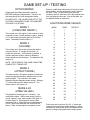
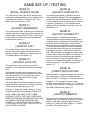
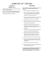
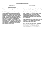
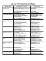
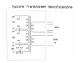
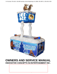
OWNERS AND SERVICE MANUAL
INNOVATIVE CONCEPTS IN ENTERTAINMENT INC.
TABLE OF CONTENTS
TABLE OF CONTENTS
INTRODUCTION………………………………………...PAGE 3
INTRODUCTION
•
•
GAME FEATURES
GAME PLAY
1
SET-UP / TESTING / MAINTENANCE………………..PAGE 4 - 9
SET UP/ TESTING/
• SAFETY PRECAUTIONS
MAINTENANCE
2-5
PROGRAMMING
6-9
•
•
•
GAME SET-UP
TESTING
CLEANING
QUICK TROUBLESHOOTING…………………………PAGE 10
•
PROBLEMS AND SOLUTIONS
QUICK
TROUBLESHOOTING
10-11
GAME
REPAIR…………………………………………..PAGE
11 - 17
•
•
•
MECHANICAL REPAIR
ELECTRICAL / ELECTRONIC REPAIR BASIC
ADVANCE TECHNICAL INFORMATION
GAME REPAIR
12-14
PARTS LISTINGS……………………………………….PAGE 18 - 23
SCHEMATICS / WIRING DIAGRAMS………………...PAGE 24 - 42
PARTS LISTINGS
SCHEMATICS
WARRANTY INFORMATION
REVISION B
15
16-32
33
4/08/2008
INTRODUCTION
GAME FEATURES
GAME PLAY
This game has many outstanding features making it
the perfect game for just about any location.
The game begins when the player has inserted
enough money to create 1 “credit”.
The game was designed with the location in mind,
featuring unparalleled flexibility in regards to custom
game set-up and programming. Virtually all game
play, and ticket dispensing options are operator
adjustable, practically letting the operator “build his
own game.”
The game has a ring of light bulbs encircling the
playfield. A lit bulb encircles the field every second
and a half. The object of the game is to stop the
light between two neon arches located in the middle
of the play zone.
CYCLONE™ has many unique features for the
“Ticket Spitter” part of the game. Its Centerpiece
design sets it apart from all other games in its
category. Its Game Play, which is ALL SKILL,
having no bounces, rolls, flips, or other chancy
situations, also showcases its creative design.
These and other features, give the players
something that keeps them playing time and time
again.
Reliability is the key word in the design of this game.
The electronics in the game have been extensively
tested to ensure years of trouble free service. The
light ring light bulbs are powered using special
circuitry and voltages to greatly enhance their life.
The neon bulbs used should last over the life of the
game.
The cabinet has been designed using only the finest
materials available. The durable scratch resistant
painted surfaces will last for years. The dome is
made from LEXAN™, an almost indestructible
material.
Game set-up is a snap. Just plug in, set a few
programmable options, and you are ready to go.
Even the programming options are easy to
understand and adjust.
A “Tickets Owed Display” is used for each station to
show tickets owed to the player. More on this
feature is given in the game play section.
Each light bulb zone has a “ticket” value associated
with it. As you get closer to the two neon arches in
the center of your zone, the ticket value increases.
Between the two neon arches described above is
the game JACKPOT. This is where a large number
of tickets can be won.
Once the game begins you have one chance to stop
the lights (for each credit inserted). Wherever the
light stops is how many tickets the game pays out.
Each time the jackpot is NOT hit, the jackpot value
increases by one or more tickets, (if the
incrementing jackpot option is selected). When the
jackpot is hit, a jackpot routine including special
lights and sounds is displayed.
Additional games can be played while tickets are
dispensing.
The game also has a unique “Tickets Owed” display.
This display has many uses. When tickets are won,
the amount won are displayed, and then counted
down as the tickets are dispensed. This is a handy
feature in the event that the game runs out of tickets
while dispensing, or if the game is out of tickets. If
the game cannot dispense the tickets it should, it will
keep adding the number it should dispense to the
tickets owed display, and thus allow the player to
continue playing the game until an attendant can be
contacted. This feature is also very helpful if the “do
not dispense tickets on jackpot” option is chosen. It
may be desirable to NOT dispense tickets if the
jackpot is set to a very high number of tickets. This
will be valuable, as the number of jackpot tickets
won would then be added to the display, then the
ticket dispenser will lock until an attendant is
located, and he resets the dispenser.
GAME SET-UP / TESTING
SAFETY
PRECAUTIONS
POWER RANGE
90 – 110 V.A.C.
110 – 130 V.A.C.
IMPORTANT: FAILURE TO FOLLOW THESE
DIRECTIONS CLOSELY COULD CAUSE SERIOUS
DAMAGE TO YOUR GAME.
200 – 220 V.A.C.
220 – 240 V.A.C.
WARNING: WHEN INSTALLING THIS GAME, A
3-PRONG GROUNDED RECEPTACLE MUST BE
USED. FAILURE TO DO SO COULD RESULT IN
SERIOUS INJURY TO YOURSELF OR OTHERS.
FAILURE TO USE A GROUNDED RECEPTACLE
COULD ALSO CAUSE IMPROPER GAME
OPERATION, OR DAMAGE TO THE
ELECTRONICS.
DO NOT DEFEAT OR REMOVE THE GROUNDING
PRONG ON THE POWER CORD FOR THE SAME
REASONS AS GIVEN ABOVE. USING AN
IMPROPERLY GROUNDED GAME COULD VOID
YOUR WARRANTY.
PAY SPECIAL ATTENTION TO THE SET UP
SECTION BELOW, REGARDING THE VOLTAGE
SETTINGS.
GAME SET-UP
BEFORE PLUGGING THE GAME IN, OR TURNING
IT ON, BE SURE THE GAME HAS BEEN SET TO
THE PROPER VOLTAGE. YOUR GAME SHOULD
COME PRE-SET FROM THE FACTORY TO THE
CORRECT VOLTAGE, HOWEVER IT IS A GOOD
IDEA TO CHECK THE A.C. WALL RECEPTACLE
VOLTAGE BEFORE PLUGGING THE GAME IN.
The Game comes with 4 available voltage settings
as described below. These settings should be used
to provide power in the correct range to the game
without over or under powering it.
VOLTAGE SETTING
110
120
220
240
The game uses a POWER MODULE to handle all of
the power distribution chores on the game. It
incorporates an ON-OFF switch, primary A.C. game
fusing, and power switching capabilities, for using
the game with a wide variety of A.C. voltages by
re-strapping the main transformer.
A.C. LINE VOLTAGE
ADJUSTMENT
To adjust the game for a different A.C. voltage:
1. Unplug the game from the outlet
2. Disconnect the power cord from the power
module.
3. Using a small flat blade screwdriver, pry the fuse
holder from the power module.
4. Notice a small window on the fuse holder with an
arrow that points to the voltage the game is
presently set alt.
5. Using the small flat blade screwdriver, lift the
retaining tab that holds the voltage selector in
the fuse holder.
6. Rotate the voltage selector until the voltage you
want is displayed in the voltage select window.
7. Push the voltage selector back into the fuse
holder until it snaps into place. NOTE: Do not
force the selector into the fuse holder. If it does
not go in easily, it is not being installed correctly.
8. Snap the fuse holder assembly back into the
power module.
9. Plug the power cord back into the receptacle in
the power module, and into the wall outlet.
NOTE: WHEN CHANGING FROM 110-120 TO 220240, LOWER THE MAIN FUSE VALUE BY ½.
WHEN CHANGING FROM 220-240 TO 110-120,
DOUBLE THE MAIN FUSE VALUE.
GAME SET-UP / TESTING
PROGRAMMING
YOUR GAME
This section will give you a detailed explanation of
the functions and operating characteristics of each
of the programming buttons. Please read this
section carefully to avoid problems with your game.
NOTE: THE PROGRAMMING BUTTONS SHOWN
BELOW MAY BE LOCATED EITHER ON THE
MAIN P.C. BOARD AS ILLUSTRATED, OR ON A
CONTROLL BRACKET ATTACHED TO THE BLUE
ACCESS DOOR.
SELECT BUTTON
(SW2)
This button is used to advance through all of the
various programming option modes. Each push of
this button, will move you to the next programmable
option. The option number is displayed on the large
“JACKPOT” display.
STEP BUTTON
(SW3)
Each push of this button will advance you to the next
available “value” for a particular programmable
option. The value for that option is shown on the
smaller “TICKETS OWED” display located on the
control panel.
SW1
PROGRAMMING
BUTTON
SELF TEST MODE
(SW4)
SW2
SELECT BUTTON
When this button is pressed, the game goes into
“Self Test” mode. In this mode, the game will
advance the lights slowly, so it is easier to se if any
light bulbs have burned out. Also, each push on any
of the control panel push buttons will activate a
sound, to test each game sound as well as each
push button.
SW3
STEP BUTTON
SW4
SELF TEST
BUTTON
QUICK START
(SW5)
SW5
When this button is pushed, a game will play,
however NONE OF THE TICKET DISPENSERS,
OR ANY COUNTERS WILL WORK. This allows
game testing with out affecting accountability. If
ticket dispensers must be tested, then a normal
game must be played.
PROGRAMMING BUTTON
(SW1)
This button is used to enter the “Programming”
mode. It is located on the Main P.C. Board in the
lower left hand corner, or on the blue access door of
the game. Press this button once to enter the
programming mode.
Once in this mode you can push SW2 or SW3 to
make adjustments to the game.
To exit the programming mode and return to game
play, push this button once again.
GAME SET-UP / TESTING
OPTION MODES
Please read the setting information carefully
BEFORE making any adjustments. Failure to set
options properly can yield unexpected results.
PLEASE NOTE: THE VALUES PRE-SET AT THE
FACTORY HAVE BEEN FOUND TO WORK BEST
FOR MOST LOCATIONS.
Below is a table that indicates the 26 zones for each
player station, and the associated “mode” number
for each. Zone 1 is the furthest zone from the
Jackpot to the left, while zone 26 is the furthest zone
from the jackpot to the right. Also in this table, are
the default values for each zone.
LIGHT RING ZONE VALUES
MODE 1
(COINS PER CREDIT)
MODE
ZONE
DEFAULT
4
1
1
The number set in this option, is the number of coins
necessary to earn 1 credit and play 1 game. Setting
a “0” in this mode will set the game in “Free Play”
mode. The default for this mode is “1”.
5
2
2
6
3
2
7
4
3
8
5
3
9
6
4
10
7
4
11
8
5
12
9
5
13
10
6
14
11
7
15
12
8
16
13
10
17
14
10
18
15
8
19
16
7
20
17
6
21
18
5
22
19
5
23
20
4
24
21
4
25
22
3
26
23
3
27
24
2
28
25
2
29
26
1
MODE 2
(VOLUME)
The number set in this mode controls the relative
volume of sound. “0” equals the minimum, “9”
equals the maximum. As this button is pushed, a
sound is played to make it easier to determine
where the volume should be set. The default for this
mode is “5”.
NOTE: THE SOUND IN THIS GAME CANNOT BE
COMPLETELY TURNED OFF.
MODE 3
(ATTRACT MODE)
The attract mode in this game consists of the theme
song being played whenever called to do so by the
game program. The numbers in this mode
represent minutes between attract modes. Setting a
“0” in this mode turns the attract mode off. The
default value in this mode is 3.
MODE 4-29
(ZONE VALUES)
The playfield is broken up into 3 “sections”, 1 for
each player station. Within each section, lies the
center “Jackpot” zone, with a series of 26 lights, 13
to either side of it. Each light has a point value
associated with it. Each light can be independently
set for a point value different from that set at the
factory. Each of these lights is a separate “zone”.
Each zone can be set from 0 to 20. If values are
changed from the factory default settings, it will be
necessary to change the numbers indicated on the
game by using the supplied decal overlay sheets.
GAME SET-UP / TESTING
MODE 30
(INITIAL JACKPOT VALUE)
The value shown is the value of the Jackpot (zone
between the 2 center arches) when the game is first
powered up, or just after a Jackpot is won. The
default value for this mode is “100”.
MODE 31
(JACKPOT INCREMENT)
The number shown here, is the amount of tickets the
Jackpot value will increase by each time the game is
played, and the Jackpot IS NOT WON. Setting a “0”
for this mode will turn the incrementing feature off.
Default for this mode is “1”.
MODE 32
(JACKPOT CAP)
The number shown in this mode is the maximum
amount of tickets the game can dispense when
hitting the Jackpot. Setting a “0” turns the cap off.
The default value for this mode is “0”.
MODE 33
(JACKPOT LOCK-UP)
This option allows the operator the choice of
whether or not to dispense tickets when the jackpot
is hit.
If the operator normally sets the jackpot to a very
high value, he may not wish to dispense the tickets
when the jackpot is hit. If the game has a lower
Jackpot set, it is a good idea to let the game
dispense tickets by itself.
It is usually better to let the game dispense tickets,
as part of the fun of the game is watching all those
tickets come out when the jackpot is hit.
Setting a “1” dispenses tickets. Setting a “0” does
not allow ticket dispensing when the Jackpot is hit.
NOTE: WHEN THE GAME IS SET TO NOT
DISPENSE TICKETS, THE TICKET DISPENSER
RESET BUTTON MUST BE PRESSED AGAIN FOR
THE GAME TO RESUME DISPENSING ANY
TICKETS AT THAT STATION. EACH PLAYER
STATION HAS A RESET BUTTON LOCATED ON
THE COIN MECH HOLDER.
MODE 34
(JACKPOT DIFFICULTY)
To make the game easier or harder to win, this
option should be adjusted. The value displayed is
equal to how may milliseconds the “WINDOW” to
win the Jackpot is open. (A millisecond is 1/1000 of
a second.) A setting of “1” is the hardest and a
setting of “20” is the easiest. The default value for
this mode is “3”.
MODE 35
(JACKPOT WINABILITY)
This mode adds a valuable feature to those
locations that have large variations in age groups.
Under the normal circumstances, the operator sets
up MODE 34 for the best payout for his location.
However this may be difficult for some age groups.
There are also circumstances where the operator
may want the jackpot to be won on an average of
XXX amount of games. This option will allow for
that. When this option is selected, no matter what
window value is chosen in MODE 34, the game will
open the window up to 20 milliseconds (easiest)
every XXX games. Every XXX games, is the
number you choose on this setting. A setting of “0”
turns this option off. The default setting for this
option is “0”.
MODE 36
(CREDIT DISCOUNTING)
When this mode is enabled, the game will give you 1
free credit for every XXX coins inserted into the
game AT ONCE. A setting of “0” turns this mode of.
Example: If “2” is chosen, for every 2 coins
inserted, 1 free game will be given. If “4” is chosen,
for every 4 coins inserted, 1 free game will be given.
The default value for this option is “0”.
MODE 37
(JACKPOT MEMORY)
This option allows the game to revert to the initial
Jackpot value, (see mode 17) or keep the last value
shown on the display when the game is shut off.
Setting a “0” resets the value, setting a “1” retains
the value. The default value is “1”.
GAME SET-UP / TESTING
MODE 38
(RESET ALL)
When this mode is selected, the game will revert to
all factory default settings.
SET “1” THEN EXIT PROGRAMMING MODE TO
RESET ALL VALUES TO FACTORY DEFAULT.
The default value for this mode is “0”.
TESTING
After the initial programming adjustments have been
made, it’s time to test your game for proper
operation.
1. Locate the game to its permanent location.
2. Be sure the game has been properly plugged
into a 3 prong grounded outlet, and that the
receptacle is in good working order.
3. If using an extension cord, be sure it is a 3-prong
grounded type of at least 16 Ga. materials.
4. Adjust the leg levers and lock into position.
5. Verify that the game is set up for proper voltage,
and the power to the game is on.
6. Insert coins at least ten times into each coin
mechanism to assure proper operation. An
audible sound should be heard each time a coin
is dropped.
7. Check the coin counter (located inside the blue
coin door) and check for proper operation.
8. Run tickets through each ticket dispenser by
playing games at each station. Check that
tickets do not get stuck behind ticket louver.
9. Check each ticket counter for proper operation.
10. Check to see that the proper amount of tickets
are dispensed based on the numbers shown on
the playfield.
11. Check that all door locks work smoothly.
12. Check game volume during busy time at location
to set it at the proper level.
IF YOU HAVE ANY QUESTIONS OR COMMENTS
REGARDING INSTALLATION OR PROPER
FUNCTION OF THE GAME, PLEASE CALL OUR
SERVICE DEPARTMENT AT 1-716-759-0360
MAINTENANCE
GENERAL
MAINTENANCE
CLEANING
This game has been designed for an absolute
minimum amount of maintenance.
Regular cleaning of the game will keep it looking
new, and greatly enhance its appeal.
The light ring light bulbs have been designed
into the game in such a fashion as to greatly
extent their life. However, eventually they will
reach the end of their life span. When this time
comes, you will notice that 2 or 3 bulbs have
burned out within a couple of weeks time from
each other. At this point, it is advisable to
change all of the bulbs. The bulbs are a very
simple push in type, very easy to change, and
very inexpensive. Changing all of the bulbs at
once, will save you work in the long run, and
keep the game looking good.
Clean the dome with a spray type furniture
polish. Pledge™ is a very good cleaner. It will
fill in minor scratches, and give the plastic
surface a deeper, clearer look. Avoid using
glass cleaners, as they dry out the plastic and
give it a hazy look.
Clean the cabinetry with a good cleaner such as
Fantastik™ or 409™ and a soft rag. A mild
soapy solution can also be used.
NOTE: DO NOT USE ALCOHOL, THINNERS
OF ANY KIND, OR PINBALL PLAYFIELD
CLEANERS ON ANY OF THE CABINET
SURFACES, ESPECIALLY THE DECALS.
QUICK TROUBLESHOOTING
PROBLEM
NO GAME POWER
PROBABLE CAUSE
ON-OFF SWITCH ON THE GAME IS TURNED OFF
BLOWN A.C. POWER FUSE
GAME NOT PLUGGED OR CORD DAMAGED
BAD TRANSFORMER
TRANSFORMER HARNESS NOT CONNECTED
BAD POWER MODULE
SOLUTION
TURN POWER ON
REPLACE WITH PROPER FUSE
CHECK POWER CORD
CHECK FOR PROPER VOLTAGES
CHECK HARNESS
REPLACE POWER MODULE
GAME WILL NOT TAKE MONEY BAD COIN SWITCH
OR GIVE CREDITS CORRECTLY COIN DISCOUNTING SET WRONG
COINS PER CREDIT SETTING INCORRECT
BAD COIN MECHANISM
LOOSE OR DAMAGED HARNESSING
BAD MAIN P.C. BOARD
BAD 5 VOLT POWER SUPPLY FUSE
CHECK W/METER AND REPLACE
CHECK PROGRAMMABLE SETTING
CHECK PROGRAMMABLE SETTING
ADJUST OR REPLACE
CHECK W/METER—REPAIR
REPAIR OR REPLACE MAIN BOARD
CHECK AND REPLACE FUSE
TICKETS DO NOT DISPENSE
OR DISPENSE INCORRECTLY
ZONE VALUES SET UP INCORRECTLY
TICKET RESET BUTTON NOT PUSHED
TICKET DISPENSER OPTICAL DIRTY
TICKET DISPENSER HARNESSING BAD
TICKET DISPENSER BAD
BAD MAIN P.C. BOARD
BAD 5 VOLT POWER SUPPLY FUSE
CHECK PROGRAMMABLE SETTING
PRESS RESET BUTTON
CLEAN OPTICAL SENSOR
CHECK W/METER AND REPAIR
REPLACE DISPENSOR
REPLACE MAIN P.C. BOARD
CHECK AND REPLACE FUSE
NEON BULBS DO NOT LIGHT
BAD NEON BULB
BAD NEON P.C. BOARD
BAD MAIN P.C. BOARD
BAD NEON POWER SUPPLY FUSE
BAD NEON HARNESSING
BAD 5 VOLT POWER SUPPLY FUSE
TEST BULB AND REPLACE
REPLACE NEON P.C. BOARD
REPLACE MAIN P.C. BOARD
CHECK AND REPLACE FUSE
CHECK W/ METER AND REPAIR
CHECK AND REPLACE FUSE
RING LIGHT BULBS DO NOT
LIGHT
BAD LIGHT BULB
BAD LIGHT RING P.C. BOARD
BAD INTERCONNECT HARNESSING
BAD MAIN P.C. BOARD
LIGHT RING POWER SUPPLY FUSE BAD
BAD 5 VOLT POWER SUPPLY FUSE
REPLACE LIGHT BULB
REPLACE LIGHT RING P.C. BOARD
CHECK W/METER AND REPAIR
REPAIR OR REPLACE P.C. BOARD
CHECK AND REPLACE FUSE
CHECK AND REPLACE FUSE
SCORE DISPLAYS DO NOT
WORK
BAD 12 VOLT STATION FUSE
BAD 5 VOLT POWER SUPPLY FUSE
BAD SCORE DISPLAY P.C. BOARD
BAD MAIN P.C. BOARD
BAD SCORE DISPLAY HARNESSING
CHECK AND REPLACE FUSE
CHECK AND REPLACE FUSE
REPAIR OR REPLACE P.C. BOARD
REPAIR OR REPLACE P.C. BOARD
CHECK W/METER AND REPAIR
JACKPOT LIGHT DOES NOT
LIGHT
BAD 12 VOLT STATION FUSE
BAD 5 VOLT POWER SUPPLY FUSE
BAD SCORE DISPLAY P.C. BOARD
BAD MAIN P.C. BOARD
BAD SCORE DISPLAY HARNESSING
CHECK AND REPLACE FUSE
CHECK AND REPLACE FUSE
REPAIR OR REPLACE P.C. BOARD
REPAIR OR REPLACE P.C. BOARD
CHECK W/METER AND REPAIR
LOW / NO TICKET INDICATOR
DOES NOT WORK
BAD INDICATOR L.E.D.
L.E.D. INSTALLED BACKWARDS
STATION HARNESSING BAD
TICKET MICRO SWITCH BAD
MAIN P.C. BOARD BAD
REPLACE L.E.D.
REVERSE L.E.D.
CHECK W/METER AND REPAIR
REPLACE MICRO SWITCH
REPAIR OR REPLACE P.C. BOARD
STORM STOPPER BUTTON
DOES NOT STOP LIGHT
BAD BUTTON SWITCH
BAD HARNESSING
BAD MAIN P.C. BOARD
REPLACE SWITCH
CHECK W/METER AND REPAIR
REPAIR OR REPLACE P.C. BOARD
GAME REPAIR
WARNING: ALWAYS REMOVE POWER TO THE
GAME BEFORE ATTEMPTING ANY SERVICE,
UNLESS NEEDED FOR SPECIFIC TESTING.
FAILURE TO OBSERVE THIS PRECAUTION
COULD RESULT IN SERIOUS INJURY TO
YOURSELF OR OTHERS.
OPERATIONAL
BACKGROUND
The CYCLONE™ coin operated amusement game
has been designed for an absolute minimum of
service. Special circuitry prolongs the life of the
incandescent light bulbs. In addition, the neon bulbs
have a life span measured in years.
The Main P.C. board has been designed with 7
separate P.C. mounted power supplies, to segregate
different areas of the electronics. In other words, if 1
station goes down, the other 2 stations will continue
to work. If the sound goes down, the rest of the
game will continue to play, etc. Additionally the
power supplies are all fan forced cooled.
The Light Ring P.C. Boards were designed to add
reliability to the game, by eliminating the massive
amount of wiring that would be needed for the 84
light ring bulbs used. The light sockets on the board
were chosen to allow for the least expensive bulbs
possible to be used. The boards were designed to
change quickly and easily in the unlikely event that
something goes wrong with one of them.
TROUBLESHOOTING
PHILOSOPHY
To find problems with this game, always first check
what should be obvious. See that the game is
plugged in, and all of the fuses on the game are
good. This includes the fuse that is located INSIDE
the power module.
Next, check to see that all of the connectors are
firmly seated, and that none of the wires have pulled
out of them.
When trying to find out if specific components are
bad or not, try swapping them with components from
another player station to see if the problem moves
with the component, or stays where it was. This will
help you to know if you have a problem with a
specific component, or maybe a problem with either
the wiring or the Main P.C. Board.
Use extreme caution when using probes or volt
meters if the game is powered up. If doing
continuity checks, it is important to disconnect the
harnessing at both ends, as attached they may yield
erroneous results.
If P.C. Boards are suspected as causing problems,
check to see that all I.C. chips are firmly seated on
the boards.
If light bulbs are suspected, swap them with one that
is known to work to narrow the problem down to bulb
or P.C. Board.
MAIN P.C. BOARD
REPLACEMENT
1. Remove all A.C. power from the game.
2. Carefully remove all of the connectors from the
P.C. Board.
3. Remove the 4 long hexagon nuts that secure the
board to the mounting bracket.
4. Gently pull the P.C. board from the mounting
bracket.
5. Re-install in the reverse order.
LIGHT RING P.C. BOARD
REPLACEMENT
NOTE: BE EXTREMLY CAREFUL NOT TO HIT A
NEON BULB SOCKET FROM THE BOTTOM, AS
THEY ARE RELATIVELY FRAGILE.
1. Remove all A.C. power to the game.
2. Remove the harnesses to the suspected bad
P.C. Board.
3. Remove the light bulbs from the bad board.
4. Remove the 4 screws that hold the P.C. board to
the bottom of the play field.
5. Re-assemble in reverse order.
GAME REPAIR - BASIC
NEON BULB
REPLACEMENT
WARNING: NEON TRANSFORMERS EMIT HIGH
VOLTAGE.
BE CAREFUL WHEN SERVICING NEON TUBES
AS THEY ARE MADE OF GLASS AND ARE
THEREFORE VERY FRAGILE.
1. Remove all A.C. power to the game.
2. Remove the 2 single pin mate-lock connectors
that connect the bad bulb to the neon
transformer P.C. board.
3a. For “U” shaped bulbs, remove the 2 nuts that
secure the sockets to the playfield.
3b. For pie shaped neon tubes, unsnap the neon
from the standoffs.
4. Remove the old neon and pull the wires up
through the mounting or access holes.
5. When re-assembling the “U” shaped neon tubes,
be sure to use the foam washer. NOTE:
INSTALL THE MOUNTING NUTS LOOSELY.
THE NEON SHOULD ROCK BACK AND
FORTH SLIGHTLY WHEN INSTALLED
PROPERLY.
6. When re-assembling the pie shaped neon tubes,
snap the neon into the standoffs evenly, the 2
closest to the outside first, then the 2 closest to
the center.
7. Re-connect the wires to the neon transformer
P.C. board and test for proper operation.
NEON TRANSFORMER P.C.
BOARD REPLACEMENT
NOTE: BE CAREFUL WHEN SERVICING THE
NEON TRANSFORMER P.C. BOARD, AS THE
BOARD CONTAINS SMALL DIAMETER WIRES
THAT COULD BECOME BROKEN WITH ROUGH
HANDLING.
BEFORE REMOVING ANY CONNECTORS, NOTE
EXACTLY WHERE THEY WERE REMOVED
FROM, SO THE LIGHTS WILL LIGHT IN THE
PROPER SEQUENCE WHEN RE-INSTALLED.
1. Remove all A.C. power from the game.
2. Remove the Harnessing from the Main P.C.
Board with the mate-lock connectors.
3. Remove the 3, six pin mate-lock connectors.
4. Remove the 6 single pin mate-lock connectors.
5. Remove the 4 corner screws that hold the neon
board to the bottom of the playfield. NOTE: THE
4 SCREWS IN THE CENTER OF EACH SIDE
OF THE BOARD DO NOT COME OUT.
6. Re-assemble in reverse order. NOTE: BE
SURE THE BULBS LIGHT IN THE PROPER
SEQUENCE, AS DESCRIBED BELOW.
BULB SEQUENCE
1. The neon arches in the center of each Jackpot
should alternately flash on and off.
2. The neon arches between the 3 player stations
should remain lit.
3. When the Jackpot is hit, the neon bulbs should
pulse from the far side of the game, to the
Jackpot area.
4. The pie shaped neon should light only when the
ring light is lit in its zone.
CONTROL PANEL P.C.
BOARD REPLACEMENT
1. Remove all A.C. power to the game.
2. Remove the two mate-lock connectors to the
P.C. board.
3. Remove the 4 long hexagon nuts that hold the
board to the bottom of the control panel.
4. Carefully slide the board from the mounting
studs.
5. Re-assemble in reverse order.
JACKPOT DISPLAY P.C.
BOARD REPLACEMENT
1. Remove all A.C. power to the game.
2. Remove the Dome.
3. Remove the four screws that hold the printed
filter on the Jackpot display housing.
4. Remove the 4 hexagon screws that hold the
Board to the housing, and remove the board.
5. Remove the mate-lock connectors.
6. Re-assemble in reverse order
Cyclone Advance Technical Information
Light Ring Is Dim Or Not Lighting:
Step 1: Check fuse F3, and make sure the fuse holder is in good condition.
Step 2: Check voltage on VR3 and VR4 (VR4 is located directly below the fan on the main board) for an
output of 13vdc. You can do this by placing your black lead of your voltmeter on the ground wire (black
wire) for the main board fan, then touching the top of the voltage regulator with the red lead of your meter.
If one or both of your regulators are below 11vdc then BOTH VR3 and VR4 need to be replaced. If the
voltage is above 11vdc you may be able to get your voltage up to 13vdc by loosening and tightening the
bolts holding the voltage regulator to the board and the heat sink.
Step 3: Check the output of DB3 (located below the heat sink) for approximately 15 volts of unregulated
DC. You can do this by measuring the voltage on resistors R49 and R50. These are located on either
side of DB3.
Step 4: Check connector P1 for approximately 18 VAC across pins 1 and 5 (red and orange colored
wires), and pins 4 and 6 (also red and orange). Remember this is AC voltage so set your meter accordingly.
Step 5: Check light ring harnessing for possible damage (exposed, broken or shorted wiring) and repair/
replace as necessary.
Step 6: Check the light ring PCB’s. To test the light ring boards you’ll need to narrow down where the
problem could be. First you need to identify what board is where. Open the blue coin door and look up at
the bottom of the playfield. You’ll see 6 light ring boards, with board #1 to the left of the blue coin door,
and board #6 to the right. The boards are in numeric order going counter-clockwise from this view. Now
disconnect the jumper wires between boards #1 and #2. Now only board #1 will light (seeing the light
rings are only a “display” of where the main board is calculating the light to be, board #1 will light as if it
was connected to the other five boards, if the board is working properly).
Cyclone Advance Technical Information
Step 6 (CONT): If board #1 works correctly, then replace the
jumper between boards #1 and #2 and remove the jumper
wires between boards #2 and #3. Boards #1 and #2 should
light accordingly. Continue this troubleshooting process until
either you have verified the light rings are operating properly
or you find the board(s) that is causing your issue. If you find
a board that doesn’t light, shuts down the light ring, or dims
the light ring, it is either the board you just connected or the
board before it in the chain.
Step 7: Try replacing U8 on the main pcb (this chip balances the regulators VR3 and VR4). If this chip
failed it may be forcing one of the regulators to be “overworked” and that overworked regulator is failing
prematurely. This would lead to replacing U8, VR3, and VR4.
No Power To One Station:
Step 1: Check fuse (F5 for Blue station, F6 for the Pink Station, and F7 for the green station).
Step 2: Check diode bridge (DB5 for Blue station, DB6 for Pink station, and DB7 for the green station) for
an output voltage of approximately 15 unregulated VDC.
Step 3: Check voltage regulator (VR5 for Blue station, VR6 for Pink station, and VR7 for Green station)
for an output of 12 VDC (measure this voltage the same way as described in section 2 of the Light Ring Is
Dim Or Not Lighting).
Step 4: Make sure there is no damage to the wiring from the main PCB to the inoperable station. On the
station connector (P2 for the Blue station, P3 for the Pink station, and P4 for the Green station) verify
there is 12 VDC across pin 1 (+12 VDC) and pin 7 (ground).
Step 5: Try swapping station connectors at the main PCB. This will help identify if there is an issue with
the station or the main pcb.
Cyclone Advance Technical Information
No Ticket Dispense/Constant Ticket Dispense On One or More Stations:
Try swapping ticket mechs or ticket mech boards between a
station that works and the station that doesn’t. This will help
verify if you issue is a main PCB or a ticket mech issue
Check the station wiring between ticket dispenser and main
PCB for damage and/or swap station connectors to see if problem follows the switch.
Make sure ticket mech is getting 12 VDC from the main PCB, if
no voltage is present check harnessing to station connector
and/or see No Power to One Station section above.
Swap chips U13 and U15 on the main PCB. These chips control various output signals, with your ticket run signal coming
from U13. After swapping these chips if your ticket mech runs
properly then replace the chip that was originally in the U13
socket.
Scrambled Displays:
Swap display with known working display from another station. If problem follows display board,
then replace display.
Try disconnecting the main to neon harness (connector P7 on main board). If your game has any
bad neon bulbs, neon harnessing, or blown components on neon board, the neon circuits may be
transmitting high frequency noise. This noise can interfere with clock, data and latch information
going to the display boards. If you disconnect the harness for the neon at connector P7 on the main
board and the displays begin to operate properly, you will need to check all harnessing, bulbs, and
the neon board for damaged wiring, exposed wiring or damaged components on the neon board.
You may also want to check the neon ballasts on the neon controller board. There are four wires
coming of each of the 12 ballasts. If these wires are touching, they can, in some cases, also cause
noise.
Swap chip U23 on the main board with a known working chip. This chip splits the clock pulse into 5
separate signals, one for each station, one for the light ring and one for the neon. If this chip is malfunctioning it may be distorting one of the outputs, causing your display to scramble.
Try swapping the microprocessor U2 on the main board. This chip controls the entire game and
could be being to fail.
Cyclone Advance Technical Information
Light In Button On/Off All The Time:
Step 1: Check to make sure the bulb is good and that the
harnessing/connectors are in good condition
Step 2: Check drive transistor on the main board (Q2 for
blue, Q3 for pink, and Q4 for green). Replace if necessary
Neon(s) Are Out:
Step 1: Check fuse F2 on main board. Also verify holder is holding fuse properly.
Step 2: Check voltage on VR2, you’ll be looking for 12 VDC.
Step 3: Check the harness/connectors between the neon board and the main board looking for possible exposed or broken wires.
Step 4: Try swapping with a known working neon bulb to see if bulb is bad or the output to that bulb is
bad.
Step 5: Replace neon transformer, 2 transistors, capacitor, and inductor (all parts available in neon
repair Kit CC2020RX and will repair only one neon circuit on the neon controller board).
L1
T1
Q13
C2
Q1
Cyclone Advance Technical Information
Game Not Saving Programming Options:
Step 1: Check battery on main board, verify it has 3.2 VDC. If not replace it
Step 2: Check D2 on main board, if this diode is open in both directions or shorted in both directions,
then replace it.
Step 3: Replace U2.
Fan On Main Board Dead:
Step 1: Check voltage to fan. This should be 12 VDC. That voltage also powers the neon controller
board.
Step 2: Replace fan. Note - if game is run without a properly running main board fan, the voltage
regulators and bridge rectifiers on the main board may fail from thermal breakdown.
Measure
fan
voltage
here.
PARTS LISTINGS
Display Boards
CC2032X— Tickets Owed Display PCB (front)
CC2033X— Jackpot Display PCB (front)
CC2035X Light Ring Board
2
1
1. E02005—906 Bulb
2. E02110— Q1 through Q15, TIP 122 Transistor
PARTS LISTINGS
1
29
2
28
3
4
27
26
25
5
24
6
23
7
8
22
10
9
21
20
11
19
18
12
13
17
14
15
1. CC3002X—Control Panel Assembly
2. CC1011-P504RX—Top Panel Overlay (blue/
right)
3. CC1035-P504—Scoreboard Housing (blue)
4. CC2020A—Neon Arch Assembly (blue)
5. CC2023A—Neon Triangle Assembly (blue)
6. CC7012—Zone Decal (left)
7. CC1011-P403LX—Top Panel Overlay (green/
left)
8. CC3004—Mirror
9. CC1035-P403—Scoreboard Housing (green)
10. CC2022A—Neon Triangle Assembly (green)
11. CC2019A—Neon Arch Assembly (green)
12. CC7005X—Storm Stopper Button Assembly
13. CC7015—Every Game Decal
14. CC2019A—Neon Arch Assembly (green)
15. CC1011-P403RX—Top Panel Overlay (green/
right)
16
16. CC1011-P102LX—Top Panel Overlay (pink/
left)
17. CC7010— Bonus Increases Decal
18. CC7013—Bonus Decal
19. CC2018A—Neon Arch Assembly (pink)
20. CC2021A—Neon Triangle Assembly (pink)
21. CC1035-P102—Scoreboard Housing (pink)
22. CC7003—Ticket Bonus Decal
23. CC7011—Zone Decal (right)
24. CC1011-P102RX—Top Panel Overlay (pink/
right)
25. CC2018A—Neon Arch Assembly (pink)
26. CC2016X—Jackpot Beacon Assembly
27. CC3003X—Playfield Assembly
28. CC2020A—Neon Arch Assembly (blue)
29. CC1011-P504LX—Top Panel Overlay (blue/
left)
PARTS LISTINGS
Neon Controller PCB
(this board is advance replaceable)
1
2
4
3
5
8
6
7
9
10
11
12
(ICE’s part numbers in parenthesis)
1. VR1— MC7805CTG voltage regulator (E20435)
2. P13 Connection to Main PCB
3. U4— IC 74HC174 (E02262)
4. U5—IC 74HC14 (E02117)
5. U2—IC 74HC165 (E02301)
6. U3—IC 74HC174 (E02262)
7. U1— IC 74HC165 (E02301)
8. Inductor L1 through L12— 3.6uH 1.5amp (E00050)*
9. Transformer T1 through T12— Neon Transformer (CC2001)*
10. Transistor Q13 through Q24—TIP122 (E02110)*
11. Capacitor c2, c7, 12, c17, c22, c27, c32, c37, c42, c47, c52, c57—10uf 50V Electrolytic
(E02325)*
12. Transistor Q1 through Q12— MJE3055T NPN (E02532)*
* All of these parts are available in a repair kit (CC2020RX). One of these repairs kits will repair one neon driver
circuit (i.e. if the neon connected to connector P1, you would replace L1, T1, Q1, Q13, and C2).
PARTS LISTINGS
17
1
16
15
2
3
4
14
11
5
13
10
6
8
7
12
9
CC2034X Main Board Connectors & Components
(part numbers in parentheses, and this board is advance replaceable)
1. Fuses (all are slow blow)—F1 3 Amp
250 Volt(E02315), F2 6 Amp 250
Volt (E02295), F3 10 Amp 32
Volt (E02259), F5 + F6 + F7
3 Amp 250 Volt (E02315)
2. Voltage Regulators—VR1-VR7
LM338k (E20809)
3. U8— LM307N Op Amp (2523)
4. P5 Misc. Connector
5. Voltage Regulator—LM358N 5vdc
(E02124)
6. Audio Amps— U17-U22 TDA2003H
Amp (E02254)
7. Program Buttons
8. Battery— 3.2v Lithium (E20407)
9. U2 Microprocessor—
MC68HC11A1P (2368)
10. P6 Light Ring Connector
11. Fuse—F8 10 Amp 32 Volt (E02259)
12. U13 & U15— 74HC273 (E02305)
13. P2, P3, P4 Station Connectors
14. P7 Neon Connections
15. Fan—12vdc (E02364)
16. Diode Bridge— 35 Amp (E02444)
17. P1 Power Connector
PARTS LISTINGS
1
2
16
15
3
4
14
5
13
6
7
12
11
8
9
10
1. CC7006—Scoreboard Overlay
2. 201—Chrome T-molding
3. E01017—LED Holder
4. 5101C—Entry Bezel
5. CC7001—Cyclone (decal)
6. CC1028-P504—Coin Door (blue)
A. CC1028-P403—Coin Door (green)
B. CC1028-P102—Coin Door (pink)
7. 5101D—Return Bezel
8. CC7002—By ICE (decal)
9. CC1025-P504—Cash Door Frame (blue)
A. CC1025-P403—Cash Door Frame
(green)
B. CC1025-P102—Cash Door Frame
(pink)
10. CC1032-P504—Cash Box Door (blue)
A. CC1032-P403—Cash Box Door (green)
B. CC1032-P102—Cash Box Door
(pink)
11. CC1022-P504—Coin Door Frame (blue)
A. CC1022-P403—Coin Door Frame
(green)
B. CC1022-P102—Coin Door Frame
(pink)
12. 5101B—Return Bezel Door
13. 5014—Lock
14. 5101A—Reject Button
15. CC7008—Coin Door Winner (decal)
16. FP2007—Speaker (not shown)
PARTS LISTINGS
MECHANICAL PARTS
CC1001
CC1007
CC1008
CC1009
CC1011
CC1014
CC1017
CC1019
CC1021
CC1022
CC1023
CC1024
CC1025
CC1026
CC1027
CC1028
CC1029
CC1030
CC1032
CC1033
CC1034
CC1035
CC1036
CC1037
CC3001X
CC3002
CC3003
CC3004
CC3005
CC3007
CC3010
CC3011
CC3012
CC3013
CC3014
CC3015
CABINET SPEAKER PANEL
MAIN P.C. BOARD MOUNTING BRACKET
CASH BOX ENCLOSURE
POWER MODULE MOUNTING PLATE
TOP PANEL OVERLAY (BLUE, L/R)
TOP PANEL OVERLAY (PINK, L/R)
TOP PANEL OVERLAY (GREEN, L/R)
SCOREBOARD MOUNTING BRACKET
COIN FUNNEL MOUNTING BRACKET
CABINET DOOR FRAME (BLUE)
CABINET DOOR FRAME (PINK)
CABINET DOOR FRAME (GREEN)
CASH DOOR FRAME (BLUE)
CASH DOOR FRAME (PINK)
CASH DOOR FRAME (GREEN)
CABINET COIN DOOR (BLUE)
CABINET COIN DOOR (PINK)
CABINET COIN DOOR (GREEN)
CASH BOX DOOR (BLUE)
CASH BOX DOOR (PINK)
CASH BOX DOOR (GREEN)
SCOREBOARD HOUSING (BLUE)
SCOREBOARD HOUSING (PINK)
SCOREBOARD HOUSING (GREEN)
DOME
CONTROL PANEL (YELLOW)
PLAYFIELD
MIRROR
MIRROR BACK (MELAMINE)
POWER MODULE ENCLOSURE
CABINET BOTTOM PLATE (MELAMINE)
CABINET TOP PLATE (MELAMINE)
PLASTIC CASH BOX
COIN FUNNEL
CABINET VERTICAL MEMBER
TOP PLATE SUPPORT
ELECTRICAL / ELECTRONIC
PARTS
CC2001
CC2002
CC2005
CC2006
CC2007
CC2008
CC2016
CC2017
CC2018
CC2019
CC2020
CC2021
CC2022
CC2023
CC2335
2005
2061
TRANSFORMER, NEON
TRANSFORMER, GAME
BUTTON LARGE ROUND YELLOW
JACKPOT LIGHT (HOUSING & AMBER COVER)
INDUCTOR 3.6 uH 1.5 AMP NEON CHOKE
MAIN P.C. BOARD HEAT SINK
NEON ARCH SOCKET NUT (PLASTIC)
NEON ARCH SOCKET
NEON ARCH (PINK)
NEON ARCH (GREEN)
NEON ARCH (BLUE)
NEON TRIANGLE (PINK)
NEON TRIANGLE (GREEN)
NEON TRIANGLE (BLUE)
RING BOARD BULB SOCKET
LIGHT RING BULB (PLAYFIELD) #906
JACKPOT LIGHT BULB #81
ELECTRICAL / ELECTRONIC PARTS
CON’TD.
2110
2117
2124
2237
2250
2253
2254
2262
2266
2297
2299
2301
2305
2320
2364
2368
2411
2417
2444
2519
2520
2521
208004
208009
276
2518
2523
PC20224
PC20407
PC20435
TRANSISTOR, TIP 120
IC 74HC14
IC LM358
IC 74HC4066 BILATERAL SWITCH
IC 74HC138
IC 74HC374
IC AUDIO AMPLIFIER TDA2003H
IC 74HC174
IC 74HC237 LATCHING OUTPUT DECODER
IC 74HC00
IC 74HC373
IC 74HC165
IC 74HC273
GAME PROGRAM E-PROM
HEAT SINK FAN
IC MC68HC11A1P MICROPROCESSOR
IC LM78L05ACZ 5% V
IC 74HC164
BRIDGE RECTIFIER 35 AMP (WIRE LEADS)
6800uf CAPACITOR 25V RADIAL
6800uf CAPACITOR 35V RADIAL
15000uf CAPACITOR 35V RADIAL
IC ULN2003A DRIVER
IC LM338K VOLTAGE REGULATOR
DISPLAY DUR14A2.5”
DISPLAY SNGL LED DUR46A 1.8”
IC CA3193E HARRIS
COUNTER 12 VOLT
BATTERY - 3.2 VOLT (BR2032)
IC LM340T-5 (7805) VOLTAGE REGULATOR
CC2005X
CC2020X
CC2032X
CC2033X
CC2034X
JACKPOT P.C. BOARD
NEON TRANSFORMER P.C. BOARD
TICKETS OWED (CONTROL PANEL) P.C. BOARD
JACKPOT DISPLAY P.C. BOARD
MAIN P.C. BOARD
HARDWARE & MISCELLANEOUS
5014
PC60615A
FP1004
FP1019
FP2007
CC2027
COIN DOOR LOCK
#2 SQUARE DRIVE BIT
LEG LEVELER MOUNTING BRACKET
LEVELER FEET
SPEAKER
POWER CORD
GRAPHICS
CC7001
CC7002
CC7004
CC7005
CC7006
CC7007
CC7008
CC7009
CC7011
CC7012
CC7013
CC7014
CC9001
CYCLONE - CABINET DETAIL
BY I.C.E. DECAL
CONTROL PANEL OVERLAY
STORM STOPPER - BUTTON DECAL
SCOREBOARD OVERLAY
PROGRAMMING DECAL
COIN DOOR WINNER DECAL
FUSE RATING / POWER DISCONNECT WARNING
PLAYFIELD ZONE DECAL - RIGHT
PLAYFIELD ZONE DECAL - LEFT
PLAYFIELD JACKPOT DECAL
ALTERNATE ZONE NUMBER DECAL SHEET
SERVICE MANUAL
A0-A13
D0-D7
To U4
To U4
To U4
To U4
To U4
To U4
Main Board Rev 4
Part A
To U10
To U10
To U10
To U4
A0-A13
D0-D7
To U7
To U7
To U7
To U7
To U7
To U9
Main Board Rev 4
Part B
To U2
To U2
To U2
To U2
To Audio Amps (TDA2002)
Main Board Rev 4
Part C
Main Board Rev 4
Part D
Main Board Rev 4
Part E
Contacts at SEGA
Machine Sales
Telephone: +44 (0) 208 391 8090
Fax: +44 (0) 208 391 8099
www.sega-amusements.co.uk
SEGA Spares
Telephone: +44 (0) 208 391 8060
Fax: +44 (0) 208 391 8096
www.segatotalsolutions.com
Customer Services
Telephone: +44 (0) 208 391 8065
Fax: +44 (0) 208 391 8096