1
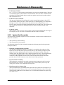
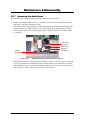
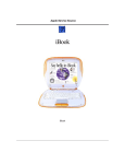
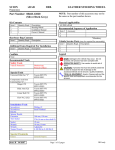
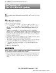
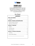
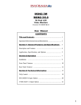
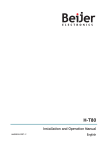
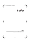
5
Chapter
Maintenance & Disassembly
5.1
Introduction
This section contains preventive and corrective maintenance procedures for the A440 Series
notebook. The first part of the section describes the computer cleaning procedures and
preferred handling procedures for sensitive components (e.g. disk drives, LCD, CPU,
batteries).
The second part of the chapter identifies all field replaceable parts with the remainder
explaining the removal and replacement procedures for the field replaceable parts.
5.2
Preventive Maintenance
Preventive maintenance is limited to cleaning the plastic case, the keyboard, and the display
screen and cleaning the floppy drive heads as required.
5.2.1
Cleaning the Computer
When it is necessary to clean the plastic case and keyboard, use a soft lint-free cloth, slightly
dampened with a mild detergent solution, or use the contents of any commercially available
computer cleaning kit.
Never use alcohol, petroleum-based solvents, or harsh detergents to clean the
notebook. Also, do not spray any liquids directly on the computer case,
keyboard, or screen. If the liquid-crystal display (LCD) screen has become
smeared or dusty, clean the screen by first applying a mild glass cleaner to a
soft, clean, lint-free cloth, and gently wipe the glass. Never apply liquids directly
on the screen surface. Moreover, do not use paper towels to clean the display
screen. Paper can scratch the display screen matte.
5.2.2
Protecting the Disk Drives
To protect the disk drives and data, back up the system disk periodically on floppy diskettes.
Periodically use a head-cleaning diskette in the floppy diskette drive to prolong the life of the
drive and to help maintain data integrity.
5.2.3
Maintaining the LCD Quality
When it comes to screen problems, heat plays a big part. After a good working session, the
typical routine is to shut the machine and close the cover. But the display surface - no matter
what type it is - and the components inside the computer radiates heat; when you close the
cover, you trap the heat against the screen. Leave the computer's cover open for about ten
minutes while the heat disperses. Make this a habit.
FIC A450 Series Service Manual
5-1
Maintenance & Disassembly
5.2.4
Maintaining the Hard Disk Drive
The hard disk drive is one of the most common parts that always gets problem. Here is some
preventive maintenance that you can do when handling the hard disk.
•
Always back up the data files from the hard disk.
•
Run a virus detecting program for possible virus infected area on the hard disk.
•
Use SCANDISK to correct any errors found in the directory and File Allocation Table
(FAT). This will also free up space from any unused sectors.
•
Never turn the computer off when the hard disk is being accessed.
•
Never move or raise the computer while the hard disk is being accessed, most especially
don't jar the hard disk as this may cause a hard disk crash.
•
Use hard disk system tools like Disk Defragmenter under Windows. This reorganizes
your hard disk by eliminating fragmentation and improves the hard disk access time.
5.2.5
Handling the Computer Battery Packs
The battery packs furnished with the computer require reasonable care and handling to ensure
efficient operation and maximum life. Periodically inspect the battery terminals and the
batteries for evidence of corrosion and oxide build-up.
To ensure that the battery packs endure normal life cycle, always observe the following
precautions when handling the battery packs:
•
Do not drop the battery packs or subject them to excessive shock and vibration.
•
Do not expose the battery packs to direct sunlight, moisture, or chemical compounds.
•
Do not disassemble the battery packs.
•
Do not use the battery packs to power other devices.
•
Do not short the battery leads or connect the battery with reversed polarity.
•
Never attempt to charge the battery packs in any way other than as described in this
manual and the User’s Manual.
•
Always charge the battery packs as soon as possible after a low battery indication.
5-2
FIC A440 Series Service Manual
Maintenance & Disassembly
5.3
Required Tools and Equipment
To troubleshoot and repair PC systems properly, you need a few basic tools:
•
•
•
•
•
Tweezers
Small flat-blade screwdriver
Small Phillips screwdriver
Regular size Phillips screwdriver
Small Hex-bolt screwdriver
All boards, options, and peripherals contain components that are sensitive to
static electricity. When handling any of these items, use wrist or ankle grounding
straps and grounded working mats. When moving or storing items, use the antistatic bags supplied with the items.
5.4
Notebook FieldField-Replaceable Parts and Assemblies
The notebook contains two major assemblies: The Cover Display LCD Assembly and the
System Unit Assembly.
Cover Display
LCD Assembly
System Unit
Assembly
Figure 5-1
n
r
u
5.4.1
Color LCD Panel
Glidepad
Keyboard
Cover Display and System Unit Assembly
o/p
s
v/w
Email / Browser Buttons
Power Button
q
t
Status LED Panel
Air Cooling Vent
Power/Charge LEDs
Cover-Display LCD assembly
The Cover-Display LCD Assembly includes the following major field replaceable units/parts
(FRUs):
•
LCD Face and Back Panel Cover
These parts are used to cover the whole LCD Panel assembly, which includes the LCD
Display Module, the LCD FPC cables, and inverter board.
FIC A440 Series Service Manual
5-3
Maintenance & Disassembly
•
LCD Display Module
12.1”/13.3”/14.1” LCD (Liquid Crystal Display) screen used for output display. This part
is assembled together with LCD Power Inverter Board, and LCD cables contained inside
the whole LCD Panel. Handle this part with care against static electricity and accidents
that can break the LCD.
•
LCD Power Inverter Board
This part or PCB (Printed Circuit Board) is used to provide high voltage to the CCFT
(Cold Cathode Fluorescent Tube) of the notebook’s LCD backlighting. It is connected to
the right side of the LCD display screen and attached to the back panel by a screw.
Exercise safety electrical precautions in handling and servicing this part. The circuit board
also includes the function for displaying the power status and battery charge LED
indicators.
•
LCD FPC Cable
The LCD FPC cable is used to convert output signals from the motherboard in driving the
LCD display screen. The cable is connected to the back of the LCD Panel.
5.4.2
System Unit Assembly
The System Unit Assembly comprise of several assemblies of which can be divided into two
major sub-assemblies.
•
•
The System Top Unit Assembly.
The System Base Unit Assembly.
The following System Top Unit Assembly includes the following major field replaceable
units/parts (FRUs):
•
Glidepad Touchpad Module Assembly
The touchpad (glidepad) pointing device module is assembled at the underside of the
Palm-rest case with the sensor pad exposed on the top. The assembly comprises of the
glidepad board, the glidepad converter board, the select buttons bracket casing, the
insulator sheet, the glidepad FPC cable, and the glidepad wire cable. The glidepad board
is assembled just underneath the select button assembly. It provides a FPC cable
connector for the glidepad converter board. The converter board on the other hand
provides the wire cable connector to the audio board of the system unit.
•
Keyboard Panel Assembly
The keyboard is assembled on top of the system unit and connected to the I/O board’s
keyboard FPC type connector. The keyboard is also secured on the system’s top unit
casing. There are no screws attached to the keyboard.
•
Heat Plate and Fan Exhaust Unit
The Fan Exhaust unit is assembled on the right side of the system unit. It comprises of a
heat plate and one fan. There are four screws securing the heat plate to the CPU module
inserted on the motherboard. The exhaust fan is secured underneath the heat plate using
two small screws.
5-4
FIC A440 Series Service Manual
Maintenance & Disassembly
•
System Upper Unit Case Assembly
The system upper unit case assembly is a thin bracket for holding the keyboard and heat
plate as well as covering the base unit. It is also where you attached the LCD panel
through the hinge sections and includes the power button and status LED cover moldings.
The following System Base Unit Assembly includes the following major field replaceable
units/parts (FRUs):
•
Battery Pack
This is one of the more easily replaceable parts. The battery pack is found on the right
side on the base unit and can be easily removed by pressing the latch underneath the unit
and pulling the battery on its handle. The battery pack is replaced as a whole and must not
be opened for repair.
•
Hard Disk Drive Module
The Hard Disk Drive is attached on the front left side of the system base unit located just
above the floppy disk drive assembly. The HDD is secured by a steel bracket and one
screw. The HDD module is a 2.5-inch hard disk drive with a maximum height of
12.7mm. The hard drive module assembly is attached to the motherboard through the
HDD board connector that plugs into the I/O board.
•
I/O Board + Charger Board
The I/O board is a daughter board attached to the system main board or motherboard.
This I/O board also has the charger board attached to it underneath. The I/O board
provides connections for the hard drive, floppy drive, and keyboard. The I/O board also
includes the cover switch for activating STR mode when the LCD cover is closed.
The charger board, on the other hand, provides the circuitry for charging the battery. It is
attached on the underneath the I/O board and can be separated from it. You need to
remove the I/O board first before you can see the charger board.
•
Audio Board
The audio board is a daughter board that is attached to the system main board or
motherboard through a connector near the PCMCIA connector. The audio board sits on
top of the battery pack compartment and is just on the right side of the I/O board. This
board provides connections for the internal microphone, speakers, CMOS battery, and
glidepad. It also includes the external audio ports for connecting external audio devices.
•
CD-ROM / DVD-ROM Drive Assembly
The CD-ROM / DVD-ROM Drive Assembly is attached on the left end side of the base
unit and is only secured with one screw. The drive module includes a metal bracket (left
and right) with two screws securing each bracket.
•
Floppy Disk Drive Assembly
The Floppy Drive assembly is located at the front left side of the base unit just underneath
the hard disk drive assembly. It is assembled to the unit with one screw secured on the
lower left corner. The module consists of the metal bracket with four screws, insulation
sheet, FDD FPC cable, and the floppy drive.
FIC A440 Series Service Manual
5-5
Maintenance & Disassembly
•
CPU
The Pentium-III/Celeron FC-PGA socket is found on the top part of the motherboard.
You will need a flat screwdriver for removing or installing the CPU. Refer to Chapter 2
on how to install and upgrade the CPU.
•
Speaker Assembly
The two internal speakers of the notebook are assembled into front left and right side
corner of the System. The Speakers are secured into a slot and speaker cable connector is
attached into the audio board.
•
Motherboard Assembly
The Motherboard assembly is the most important part of the notebook. It contains the
entire major chipsets including the core logic, PCMCIA, memory, and BIOS to operate
the whole computer. It also includes the sockets, connectors and ports completing the
functionality.
•
Internal Modem/LAN Module Assembly
If the computer includes an internal modem or an internal LAN module, it is located
underneath the motherboard using a mini-PCI slot. The output jack is inserted into the
port just beside the exhaust vent.
•
System Base Unit Case
The System Base Unit Case is where the Motherboard is placed. It includes openings for
the battery, FDD, CD-ROM and PCMCIA equipment.
5-6
FIC A440 Series Service Manual
Maintenance & Disassembly
5.5
Parts Removal and Replacement Procedures
This section contains the field service-level removal/ replacement procedures for the
notebook. The notebook is designed for optimum modularity in order to make field
replacement and maintenance easy and efficient.
5.5.1
Removing the Battery Pack
The procedure for removing and replacing the battery pack is as follows:
1. The battery pack is located on the right side of the system unit.
2. To release the battery pack, locate the battery latch found underneath the unit.
3. Push the latch to release the lock and at the same time pull the battery pack out.
4. To replace the battery pack, simply slide in the battery pack until the latch snaps in.
5.5.2 Removing the Glidepad
The glidepad module is assembled underneath the palm-rest cover case. Follow the procedure
below on how to remove the module:
Glidepad
module
Palm-rest
panel/cover
First unsnap
panel at right
corner
Glidepad
connector
Audio
Board
Figure 5-2(a)
Removing the Glidepad / Palmrest Cover
1. Remove the three screws mounted on the palm-rest assembly found underneath the unit.
2. Slowly remove the palm-rest cover by unsnapping the sides from the system base unit,
starting at the right corner panel.
3. Slowly lift the cover case, and you will find a cable connected from the glidepad to the
FIC A440 Series Service Manual
5-7
Maintenance & Disassembly
audio board. Pull the glidepad cable from the audio board to separate the palm-rest cover
from the system unit.
4. Underneath the palm-rest cover, you will see the glidepad module assembly. Remove first
the three screws on the glidepad converter board where the glidepad wire cable is
connected. Remove the FPC cable connected to it as well.
Figure 5-2(b)
Glidepad Assembly
5. When the converted board is removed, you can remove the select-button bracket casing
covering the glidepad board.
6. Replace a new glidepad module and reverse the procedure to reassemble.
5.5.3
Removing the Keyboard and Heat Plate
The internal keyboard is located just above the system top unit and is fitted in without screws
on the top unit case. Follow the steps below on how to remove the keyboard and heat plate:
1. Follow the steps on removing the Glidepad assembly (palm-rest cover). There are no
screws attached to the keyboard.
2. Remove the keyboard cover by gently pressing on it and sliding it towards right direction.
Figure 5-3
Removing the Keyboard Cover
3. Lift the keyboard and tilt it towards the LCD panel. You will find the keyboard cable
connected to the I/O board inside the unit. Release keyboard cable by sliding the ZIF
connector towards right direction.
5-8
FIC A440 Series Service Manual
Maintenance & Disassembly
Figure 5-4
Figure 5-5
Removing the Keyboard Cable
Removing the Heat Plate
4. Release the three screws securing the heat plate found on the top center. Remove the heat
sink by slightly lifting it up and sliding it towards left direction. Be careful with the CPU
fan cable that is still connected on the motherboard. Unplug the CPU fan cable. The heat
sink may be a bit difficult to pull out at first time.
5.5.4
Removing the LCD Panel
The procedure for removing the LCD Panel is as follows:
LCD hinge
LCD hinge
LCD panel
connector
Figure 5-6
FIC A440 Series Service Manual
LCD Hinge and LCD Panel Connector
5-9
Maintenance & Disassembly
1. Follow the steps above in removing the keyboard cover.
2. You will find the LCD panel connector attached to the system unit using two screws.
Remove the screws of the LCD panel connector.
3. At the back of the LCD panel connector where the I/O ports are located, you will find
another two small screws. The screws are just located on top of the printer port and VGA
port. Remove the two screws as well.
4. You now need to pull out the LCD hinge cover found at both rear corners of the system
unit where the LCD panel is attached. Use a small flat screwdriver first to unsnap the
hinge cover before pulling them.
5. There are two screws securing both LCD hinge to the system unit. Remove the screws to
separate the LCD panel from the system unit.
6. Slowly pullout the LCD panel from the system unit.
7. To remove the LCD screen itself, you need to disassemble the LCD front panel casing.
Remove the screws on the front panel as shown in the figure below. Then, carefully
separate the front panel cover from the LCD assembly.
Screws
Figure 5-7
5.5.5
LCD Face Cover Screw Locations
Removing the System Upper Case
The procedure for removing the system upper case is as follows:
1. For doing this disassembly, you need first to do the disassembly for the glidepad,
keyboard, heat plate, and LCD panel.
2. To remove the system top case, you need to remove several screws. There are nine screws
found on the top case - four small ones on the rear end and another five screws as
indicated on the figure below. Remove them all.
3. At the rear corners of the system unit on the I/O port, you will find four round screws
secured at both ends. Remove them.
4. Slowly unsnap the top case bracket from the bottom case. Pull out the top case.
5-10
FIC A440 Series Service Manual
Maintenance & Disassembly
Figure 5-8
5.5.6
Removing the Screws of the System Upper Case
Removing the Internal Hard Disk Drive
The notebook provides a built-in hard disk for the primary IDE controller. The HDD is an
industry standard 2.5” IDE disk drive and can be upgraded with another standard 2.5” HDD.
1. Remove the two screws securing the palm-rest cover underneath the system base unit.
Remove the palm-rest cover by slowly unsnapping each section of the palm-rest cover
from the base unit.
2. When you have remove the entire palm-rest cover, simply flip over the touchpad panel to
the keyboard. You will find the built-in hard disk secured with one screw at the upper left
corner of the hard disk and another screw at the upper right corner of the hard disk.
Remove the screw and carefully pull the hard disk module from the connector on the
daughter board.
3. Remove the four screws securing the hard disk to the bracket connector and replace with
another one. Plug in the hard disk module to the connector on the daughter board and
secure the screw on the upper left corner of the hard disk.
Figure 5-9 Hard Disk Drive Assemblies
FIC A440 Series Service Manual
5-11
Maintenance & Disassembly
5.5.7
Removing the Audio Board
The procedures for removing and replacing the audio board is as follows:
1. Before removing the audio board, you need first to disassemble the glidepad, keyboard,
heat plate, LCD panel, and upper casing.
2. The audio board is plugged onto the connector found on the motherboard just behind the
PCMCIA connector. The board sits on top of the battery pack compartment. The audio
board is where the speaker cable, glidepad cable, internal microphone, and RTC battery
are attached.
Audio Board
Connector
Audio Board
Internal
Microphone
Figure 5-10
Speakers /
RTC Battery
Audio Board Screws and Connectors Locations
3. There are three screws securing the audio board (see Figure 5-10). The screw on the right
corner is secured on top of the audio board, while the other screw on the left is secured
underneath the bottom case and beside the microphone jack. To replace the audio board,
remove the two screws, and plug out all cables connected to it.
5-12
FIC A440 Series Service Manual
Maintenance & Disassembly
5.5.8
Removing the Charger Board
The procedures for removing and replacing the I/O + Charger board and DC/DC board are as
follows:
Hex Bolt
Screws
I/O + Charger
Board
Figure 5-11
I/O Board Assembly
1. Before removing the I/O + charger board, you need first to disassemble the glidepad,
keyboard, heat plate, hard disk, LCD panel, upper casing, and audio board.
2. The I/O board is plugged into the middle of the motherboard. The I/O board is also where
the FDD cable, hard disk, and audio board are attached. Remove all cables connected to
it.
3. There are three screws and one hex bolt securing the I/O board (see Figure 5-11). Remove
the screws and slowly pull out the I/O board.
5.5.9
Removing the CD-ROM Module
The procedures for removing and replacing the CD-ROM module is as follows:
1. Before removing the CD-ROM module, you need first to disassemble the glidepad,
keyboard, heat plate, hard disk, LCD panel, and upper casing. The CD-ROM module is
found at the upper left side of the base unit.
2. To remove the CD-ROM module, remove the screws securing the CD-ROM bracket and
pull out the drive from the connector.
3. Slowly slide the CD-ROM module out of the base unit.
4. To replace the CD-ROM, remove the metal bracket around it.
FIC A440 Series Service Manual
5-13
Maintenance & Disassembly
CDROM
Screws
Figure 5-12
CD-ROM Screw Location
5.5.10 Removing the Internal Speaker
The internal speakers are connected on the front left and right side of the base unit assembly.
Both speakers are connected to the audio board using wire cable. Follow the procedure below
and illustration on how to remove the internal speaker:
1. The internal speakers are located on the front left and right side of the base unit. There are
no screws attached to the speakers, just unhook the speakers from the speaker
compartment case.
2. The speaker cables are directly connected to the audio board. Pull the wire cable of the
internal speakers and take out them out.
Figure 5-13
Internal Speaker Assembly
5.5.11 Removing the FDD Module
The procedures for removing and replacing the FDD module is as follows:
1. Before removing the FDD module, you need first to disassemble the glidepad, keyboard,
heat plate, hard disk, LCD panel, upper casing, CD-ROM module, audio board and I/O
board. The FDD cable is also connected to the I/O board. Detach the FDD cable also.
2. The FDD module is assembled to the lower left side of the base unit, just on top of the
hard disk drive.
3. Remove the screw securing the lower left side of the FDD metal bracket.
5-14
FIC A440 Series Service Manual
Maintenance & Disassembly
4. Slowly lift the entire FDD module and remove from the base unit.
5. To replace the FDD, remove first the metal bracket and mylar sheet.
5.5.12 Removing the CPU
For removing and installing the Socket 370 FC-PGA CPU, please refer to Chapter 2 on CPU
upgrade procedures.
Figure 5-14
Socket 370 FC-PGA
5.5.13 Removing / Replacing the Motherboard
The motherboard contains the major chipset and components needed to run the notebook.
Follow the steps below on how to remove and replace the motherboard:
1. Before removing the motherboard, you need first to disassemble the all base unit modules
mentioned in the previous sections.
2. On the motherboard, there are six hex bolts and six screws (see figures below). Remove
these hex bolts and screws.
Figure 5-15(a)
FIC A440 Series Service Manual
Motherboard Hex Bolts Location
5-15
Maintenance & Disassembly
Figure 5-15(b)
Motherboard Screws Location
3. Underneath the unit, there are two screws found on the rear corners near the tilt foot.
Remove them as well. When all screws and bolts are removed, slowly detached the
motherboard from the base unit casing.
4. After removing the motherboard, you can also pull out the I/O port bracket.
5. To remove the I/O port bracket, use a hex bolt screwdriver to remove the hex bolts.
5-16
FIC A440 Series Service Manual