1
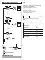
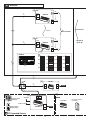
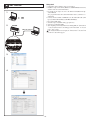
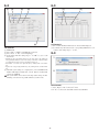
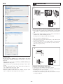
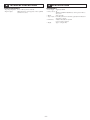
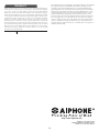
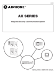
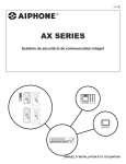
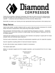
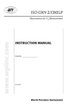
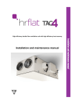
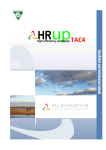
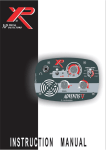
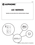
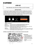
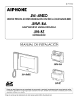
0311 A OI
GTW-LC
SERVICE MANUAL
GT System Lift control adaptor
GTW-LC
INSTALLATION & OPERATION MANUAL
CONTENTS
PRECAUTIONS
General Prohibitions
Prohibition to Dismantle the Unit
Prohibition on Subjecting the Unit to Water
1 SYSTEM CONFIGURATION
System Configuration������������������������������������������������������������������� 3
Wiring Distance������������������������������������������������������������������������������ 3
2 CONTENTS
Contents��������������������������������������������������������������������������������������������� 4
3 NAMES
Names������������������������������������������������������������������������������������������������� 4
4 MOUNTING
Mounting������������������������������������������������������������������������������������������� 5
5 WIRING
Wiring������������������������������������������������������������������������������������������������� 6
6 SETTING UP
Setup tool������������������������������������������������������������������������������������������� 8
Lift Control 1������������������������������������������������������������������������������������ 9
Lift Control 2������������������������������������������������������������������������������������ 9
Data transfer������������������������������������������������������������������������������������ 9
Combine Data������������������������������������������������������������������������������� 10
7 OPERATIONS
Residential Station or Security Guard Station Door
Release��������������������������������������������������������������������������������������������� 10
Automatic Entry (Doctor Call) Option�������������������������������� 10
8 TECHNICAL PRECAUTIONS
Technical precautions��������������������������������������������������������������� 11
9 SPECIFICATIONS
Specifications�������������������������������������������������������������������������������� 11
General Precautions
WARNING
(Negligence could result in death or serious injury.)
1. Do not dismantle or alter the unit. Fire or electric shock could result.
2. The unit must be installed and wired by a qualified technician.
3. Do not connect any non-specified power source to the +, - terminals, and do not install
two power supplies in parallel to a single input. Fire, damage to the unit, or system
malfunction could result.
4. Keep the unit away from water or any other liquid. Fire or electric shock could result.
5. Do not connect any terminal on the unit to AC power lines. Fire or electric shock could
result.
6. Do not put any metal or flammable material into the unit through the openings. Fire,
electric shock, or unit trouble could result.
7. Do not install or make any wire terminations while the lift or any other systems are
powered on. It can cause electrical shock, damage, or malfunction to the other systems.
8. When checking the operation of the lift or other systems, ensure the safety of others in
the surrounding area before starting. Failure to do so could cause an accident.
CAUTION
(Negligence could result in injury to people or damage to
property.)
1. Do not install or make any wire terminations while power supply is plugged in. It can
cause electrical shock or damage to the unit.
2. Before turning on power, make sure wires are not crossed or shorted. Fire or electric
shock could result.
3. Do not put anything on or cover the unit with cloth, etc. Fire or unit trouble could result.
4. For DC powered systems, use Aiphone power supply model specified with system. If
non-specified product is used, fire or malfunction could result.
5. Do not install the unit in any of the following locations. Fire, electric shock, or unit
trouble could result.
* Places under direct sunlight, or near heating equipment that varies in temperature.
* Places subject to dust, oil, chemicals, hydrogen sulfide (hot spring).
* Places subject to moisture and humidity extremes, such as bathroom, cellar, greenhouse, etc.
* Places where the temperature is quite low, such as inside a refrigerated area or in front
of air-conditioner.
* Places subject to steam or smoke (near heating or cooking surfaces).
* Where noise generating devices such as dimmer switches, invertor electrical appliances, are closeby.
6. When mounting the unit on wall, install the unit in a convenient location, but not where
it could be jarred or bumped. Injury could result.
7. Do not place (install) the unit in locations subject to frequent vibration or impact. Injury or damage could result if the unit falls.
GENERAL PRECAUTIONS
1. This unit is for indoor use only. Do not use outdoors.
2. As to other systems used with this device, such as the lift, comply with the Manufacturer’s Specifications and Warranty conditions.
3. The unit turns inoperative during power failure.
4. Keep the intercom wires more than 30 cm (12 inches) away from AC 100-240 V lines,
particularly AC lines for invertor electrical appliances. Noise and malfunction could
result.
-2-
1
1-1
1-1
SYSTEM CONFIGURATION
System Configuration
a. GT expanded system (For details, see the GT Series Installation & Operation Manual.)
Make sure to use GT-BCX, GT-DA(-L), GT-NS(-V), GT-DM(V).
[1] Expanded Bus control unit GT-BCX
[2] Distribution terminal (junction): Not included
[3] Lift control adaptor GTW-LC
Relay contacts: 20
[4] Bus control unit GT-BC
[5] Power supply PS-2420DIN etc.
[6] Lift controller (made by other manufacturer)
[7] Lift (made by other manufacturer)
[8] Entrance station (digital name scrolling type): Audio only or Audio/
video
Do not use direct selection GT-SW.
[7]
#16
[6]
[3] GTW-LC
Max. 8
Capacity
#9
Lift control adaptor
Maximum 16 adaptors (up to 8 adaptors per trunk)
* Capacity of other units conform to the expanded system.
[3] GTW-LC
1-2
Wiring Distance
[7]
#8
* DP = Distribution Point
[6]
0.65 mm
(22 AWG)
0.8 mm
(20 AWG)
1.0 mm
(18 AWG)
GT-BCX ~ GTW-LC
-
300 m
(980’)
-
GT-BCX ~ GT-BC
-
300 m
(980’)
-
DP ~ GTW-LC
-
300 m
(980’)
-
GT-BC ~ DP
-
5m
(16’)
-
GT-BC ~ power supply
-
5m
(16’)
5m
(16’)
Total wiring distance
GT-BCX ~ GTW-LC
-
2500 m
(8200’)
-
Diameter of wires
[3] GTW-LC
Max. 8
#1
[3] GTW-LC
[4] GT-BC
* For other Wiring Distances, see the GT Series Installation & Operation
Manual.
PS24 [5]
[2] DP
[8]
Sub trunk
1
2
A
B C
K L
9
X Y
Z
S
PS24
N O
W
T
U V
Common trunk
E F
6
8
0
or
3
5
M
P
H I
J
G
7
D
4
Q R
Entrance Station (Unit Type)
[1] GT-BCX
Entrance Station (Integrated Type)
a GT Expanded System
-3-
2
3
CONTENTS
NAMES
[3]
GTW-LC
Contents
Lift control adaptor GTW-LC (mounting bracket is included)
[1]
[3]
[2]
[4]
Names
[1]
[2]
[3]
[4]
-4-
Bus line terminal
ID setting switch
Relay output terminal
Lock release lever
4
MOUNTING
[1]
[1]
GTW-LC
[2]
Mounting
[1] Din rail
[2] Lock release lever
Mount GTW-LC to the Din rail.
* To remove GTW-LC, pull the lock release lever down.
GTW-LC cannot be mounted directly to the wall surface.
-5-
5
WIRING
[3] #8
RY1
1P
NP
RY20
1P
NP
GT-BCX
1P
NP
GTW-LC
R1
R2
to
Lift controller
Max. 8
[3] #1
RY1
GT-BCX
1P
NP
1P
NP
#9 to #16
(max. 8)
GTW-LC
R1
R2
RY20
1P
NP
GTW-LC
#1
ON
#2
ON
#3
ON
#4
ON
#5
ON
#6
ON
#7
ON
#8
ON
1 2 3 4
1 2 3 4
1 2 3 4
1P
NP
ID
1 2 3 4
1 2 3 4
1 2 3 4
1 2 3 4
1 2 3 4
#9
#13 ON
ON
1 2 3 4
#10 ON
1 2 3 4
#14 ON
1 2 3 4
1 2 3 4
#15 ON
#11 ON
1 2 3 4
1 2 3 4
#16 ON
#12 ON
1 2 3 4
1 2 3 4
1P
NP
[4]
[2] DP
4
3
2
1
1P
NP
R1
R2
GT-BC
R1
+
R2
–
PS24
1P
NP
[1]
1
2
A
B C
3
E F
5
K L
6
N O
M
S
8
W
T
U V
0
9
X Y
Z
P
H I
J
G
7
D
4
Q R
Entrance Station
(Unit Type)
Sub trunk
[5]
PS24
R1 R2
GTW-LC
PS-2420DIN
or
Common trunk
Entrance Station
(Integrated Type)
GT-BCX
+
–
a GT Expanded System
-6-
PS24
PS-2420, PS-2420S,
PS-2420UL
Wiring
a. GT expanded system (For details, see the GT Series Installation & Operation Manual.)
[1] Expanded Bus control unit GT-BCX
[2] Distribution terminal (junction): Not included
[3] Lift control adaptor GTW-LC
Maximum 16 adaptors (up to 8 adaptors per trunk)
• ID: ID setting switch (factory setting is #1)
Make sure to set corresponding ID number.
[4] Bus control unit GT-BC
[5] Power supply PS-2420DIN etc.
NP: Non-polarized
-7-
6
6-1
Setup tool
SETTING UP
* Completing settings with the setup tool is required.
1. Install the setup tool in the PC (Windows 7/VISTA/XP ®) beforehand,
and then enter the resident information.
* For details on the setup tool, refer to the GT Series Installation & Operation Manual.
Save programmed data and resident information data to your PC is recommended.
2. Connect the PC terminal of GT-BCX to the PC with USB cable (A-B
type) (included with GT-NS(-V), GT-MK, GT-DM(V)).
* PC requires USB output.
3. Start the setup tool (double-click gt_program.exe).
4. Select the system (GT or GH).
5. After inputting resident information and clicking OK, the“Lift Control
1”tab and“Lift Control 2”tab will appear if“Lift Control”is selected
in the“View”menu.
If resident information is not input, the“Lift Control 1”tab and“Lift
Control 2”tab will not appear.
1
2
GT-BCX
USB Cable (A-B type)
3
4
-8-
6-2
[1]
6-3
[2]
[3]
[1]
[4]
[5]
Lift Control 1
[1]
[2]
[3]
[4]
GTW-LC ID
Select“ON”or“OFF”for the GTW-LC connection.
Select“N.O.”or“N.C.”for the Output Type.
Set the Timer. The time setting range is“1 to 600”sec. (one second
increments)
[2]
Lift Control 2
[1] The resident information that has been entered will be displayed.
[2] Set which relay will activate in the corresponding GTW-LC for each
residence. The setting range is“1 to 20”.
6-4
1
• Clicking the upper spin button will increase the time setting, and clicking the
lower spin button will decrease the time setting. At this time, a numerical value
exceeding either the upper or lower value limits cannot be set.
• The number of seconds can be input directly by clicking inside of the Timer
box.
• Input can be set by pressing the Enter key or by clicking inside of another Timer
box.
2
[5] After GT system settings are completed, the connected GTW-LC ID
numbers will display in black if the“Check”button is clicked while
connected to GT-BCX.
The system will be in use when Connecting status is being checked.
Checking connections is not possible while the system is in use.
Data transfer
1. Select“Export”in the“Connection”menu.
2. If“Yes”is selected, the data will be transferred to GT-BCX.
-9-
7
7-1
6-5
1
OPERATIONS
1
2
G
4
M
H
I
P
W
T
R
K
T
8
U
C
3
L
V
W
0
E
6
M
P
7
Q
B
5
J
NO
9
D
J
S
2
E F
6
X Y
0
A
G
K L
8
U V
1
3
5
S
B C
D
H I
7
N
F
O
9
X
Y
Z
A
4
Z
1
Q R
2
2
Residential Station or Security Guard Station Door Release
1. Press the door release button at the residential station or security guard
station while in communication with the entrance station that made a
call.
2. The door release function will activate on the entrance station that is in
communication, and the lift will begin to move.
The lift operates according to the lift controller settings.
3
* In the cases below, the lift will not move.
• If the talk button is pressed and the residential station goes into talk mode while
the entrance is being monitored.
• When the entrance station access code is input and the door is released. In this
case, using a proximity card etc. to activate the lift to go to their specific floor.
(This function depends on the lift.)
7-2
4
1
DOCTOR
Combine Data
The data entered in the GT-BCX can be combined with the data entered
in the GT-NS(V), GT-MK or GT-DM(V), and this data can be saved as
master data.
* Import the data entered into the GT-NS(V), GT-MK, GT-DM(V) and
GT-BCX before this process.
1. Select and open the corresponding data with“Open”in the“File”
menu.
2. Selecting“Lift Control”in the“View”menu makes it possible to select“Combine Data”in the“File”menu.
3. Select and open the corresponding data.
4. Click the checkboxes for the items to be combined, and select“Combine”to combine the data. Assign a file name and save.
2
Automatic Entry (Doctor Call) Option
1. A visitor presses the call button of the entrance station.
2. If the automatic entry is set, the release mechanism is activated and the
lift will begin to move at the same time.
The lift operates according to the lift controller settings.
• For details on the automatic entry (doctor call), refer to the GT Series Installation & Operation Manual.
- 10 -
8
TECHNICAL PRECAUTIONS
9
SPECIFICATIONS
Technical precautions
Specifications
• Operating temperature: 0 °C to +40 °C (+32 °F to +104 °F)
• Repair requests:
When units do not operate properly, contact a qualified
technician for service.
• Power supply: Supplied by GT-BC
• Relay contacts: 20
AC/DC 24 V, 500mA, N.O./N.C. dry closure operation time accuracy ±2%
• Wiring:
single-pair cable
• Type of cable: Pair cable (solid wire not stranded), polyethylene insulated, diameter 0.65 ~ 1.0 mm
• Dimensions:
210 (W) x 108.5 (H) x 61 (D) mm
(8-1/4 x 4-1/4 x 2-3/8 inch)
• Weight:
Approx. 330 g (0.7 lbs.)
- 11 -
WARRANTY
Aiphone warrants its products to be free from defects of material and workmanship under normal use and service for a period of two years after delivery to the ultimate user and will repair
free of charge or replace at no charge, should it become defective upon which examination
shall disclose to be defective and under warranty. Aiphone reserves unto itself the sole right to
make the final decision whether there is a defect in materials and/or workmanship; and whether
or not the product is within the warranty. This warranty shall not apply to any Aiphone product which has been subject to misuse, neglect, accident, or to use in violation of instructions
furnished, nor extended to units which have been repaired or altered outside of the factory.
This warranty does not cover batteries or damage caused by batteries used in connection with
the unit. This warranty covers bench repairs only,and any repairs must be made at the shop or
place designated in writing by Aiphone. Aiphone will not be responsible for any costs incurred
involving on site service calls. Aiphone will not provide compensation for any loss or damage
incurred by the breakdown or malfunction of its products during use, or for any consequent
inconvenience or losses that may result.
The object area of
This equipment has been tested and found to comply with the limits for a Class B digital
device, pursuant to Part 15 of the FCC Rules. These limits are designed to provide
reasonable protection against harmful interference in a residential installation. This
equipment generates, uses, and can radiate radio frequency energy, and if not installed
and used in accordance with the instructions, may cause harmful interference to radio
communications. However, there is no guarantee that interference will not occur in a
particular installation. If this equipment does cause harmful interference to radio or
television reception, which can be determined by turning the equipment off and on, the
user is encouraged to try to correct the interference by one or more of the following
measures: • Reorient or relocate the receiving antenna • Connect the equipment into an
outlet on a circuit different from that to which the receiver is connected. Increase the
separation between the equipment and receiver. • Consult the dealer or an experienced
radio/TV technician for help.
(WEEE) is EU.
http://www.aiphone.net/
AIPHONE CO., LTD., NAGOYA, JAPAN
AIPHONE CORPORATION, BELLEVUE, WA, USA
AIPHONE S.A.S., LISSES-EVRY, FRANCE
- 12 -