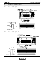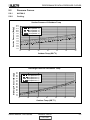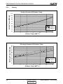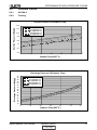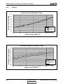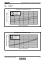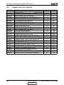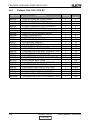
1
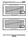
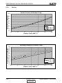
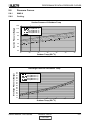
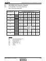
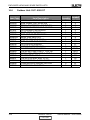
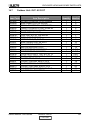
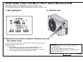
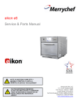
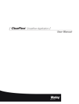
Service Manual
DUO Series
DUO Outdoor Models
DUO OU7 (9+9)
DUO OU7 (9+12)
DUO OU7 (12+12)
REFRIGERANT
HEAT PUMP
R410A
COOLING ONLY
FEBRUARY - 2006
CONTENT
LIST OF EFFECTIVE PAGES
LIST OF EFFECTIVE PAGES
Note: Changes in the pages are indicated by a “Revision#” in the footer of each effected page
(when none indicates no changes in the relevant page). All pages in the following list represent
effected/ non effected pages divided by chapters.
Dates of issue for original and changed pages are:
Original ....... 0 ........March 2005
Total number of pages in this publication is 59 consisting of the following:
Page
No.
Revision
No. #
Page
No.
Revision
No. #
Page
No.
Revision
No. #
Title ....................... 2
A ........................... 2
i ............................. 1
1-1 ........................ 2
2-1 - 2-9 ................ 2
3-1 ........................ 1
4-1 - 4-2 ................ 2
5-1 - 5-21 .............. 2
6-1 ........................ 2
7-1 ........................ 1
8-1 ........................ 1
9-1 ........................ 1
10-1 ...................... 1
11-1 ....................... 2
12-1 ...................... 2
13-1-13-2 .............. 1
14-1-14-8 .............. 2
Appendix A.............1
• Zero in this column indicates an original page.
*Due to constant improvements please note that the data on this service manual can be modified
with out notice.
**Photos are not contractual
A
Revision Y05-02
CONTENT
Service Manual - DUO Series
TABLE OF CONTENTS
Table of Contents
1.
INTRODUCTION ...................................................................................................1-1
2.
PRODUCT DATA SHEET ......................................................................................2-1
3.
RATING CONDITIONS ..........................................................................................3-1
4.
OUTLINE DIMENSIONS .......................................................................................4-1
5.
PERFORMANCE DATA AND PRESSURE CURVES ..........................................5-1
6.
CHARACTERISTICS SOUND LEVEL ..................................................................6-1
7.
ELECTRICAL DATA ..............................................................................................7-1
8.
WIRING DIAGRAMS .............................................................................................8-1
9.
ELECTRICAL CONNECTIONS .............................................................................9-1
10. REFRIGERATION DIAGRAMS .............................................................................10-1
11.
TUBING CONNECTIONS......................................................................................11-1
12. CONTROL SYSTEM .............................................................................................12-1
13. TROUBLESHOOTING ..........................................................................................13-1
14. EXPLODED VIEWS AND SPARE PARTS LISTS .................................................14-1
15. APPENDIX A .........................................................................................................15-1
Service Manual - DUO Series
Revision Y05-02
i
INTRODUCTION
1.
INTRODUCTION
1.1
General
The DUO multi split R410A outdoor unit series, comprise the following ST (cooling only)
and RC (heat pump) models:
1.2
• Cooling Only
OU7 (9+9) ST, OU7 (9+12) ST, OU7 (12+12) ST
• Heat Pump
OU7 (9+9) RC, OU7 (9+12) RC, OU7 (12+12) RC
Main Features
• R410A refrigerant
• Built in Deicing Controller.
• High COP
• Outdoor coil with hydrophilic louver fins for RC units.
• Metal sheets protected by anti - corrosion paint work allowing long life
resistance.
• Compressor mounted in a soundproofed compartment
• Easy installation and service.
1.3
Tubing Connections
Flare type interconnecting tubing to be produced on site.
For further details please refer to APPENDIX A on this manual, and to the relevant
indoor service Manual,
1.4
Inbox Documentation
Each indoor unit is supplied with its own installation and operation manuals, an
additional instillation guide is provided in the DUO outdoor package.
1.5
Matching Table
INDOOR UNITS
OUTDOOR UNITS
MODEL
REFRIGERANT
WNG9
DUO 9+9 ST/RC
R410A
√
DUO 9+12 ST/RC
R410A
√
DUO 12+12 ST/RC
R410A
Series Manual - DUO Series
Revision Y05-02
CONTENT
WNG12
ALPHA 9
ALPHA 12
√
√
√
√
√
√
1-1
PRODUCT DATA SHEET
2.
PRODUCT DATA SHEET
2.1
WNG 9+9 / OU7- 0909
Model Indoor Unit
WNG 9+9
Model Outdoor Unit
Installation Method
Characteristics
OU7-0909
Wall Mounted
(1)
Capacity
(1)
Power Input
(1)
COP
Power Supply
Rated Current
Starting Current
Circuit Breaker Rating
Fan Type & Quantity
(2)
Airflow
External Static Pressure
Cooling
19520
Heating
18315
kW
kW
W/W
V/Ph/Hz
A
A
A
5.72
1.78
3.2
5.37
1.67
3.2
230/1/50+/-10%
7.7
m /hr
Pa
3
450
H/M/L
H/M/L
dB (A)
dB (A)
L/hr
mm
mm
kg
mm
44
28
Sound Power Level
(4)
Sound Pressure Level
Moisture Removal
Condensate Drain Tube I.D.
Dimensions
Weight
Package Dimensions
W/H/D
W/H/D
Units per Pallet
Stacking Height
Crossflow*1
380
N/A
46
31
2*0.9
16
810*190*285
11
945*395*655
Units
Units
OUTDOOR
Dimensions
Weight
Package Dimensions
Packaged Weight
Units per Pallet
Stacking Height
Refrigerant Type
Refrigerant Charge ST/ RC outdoor
Liquid Line
Suction Line
Connections
Max. Tubing Length
Between Units
Max. Height Difference
1)
(2)
(3)
(4)
49
35
Capillary tube
Rotary
Axial*1
850
H/L
H/L
H/L
H/L
RPM
3
m /hr
dB (A)
dB (A)
W/H/D
mm
kg
mm
kg
Units
Units
900*680*340
72
985*730*406
74
6
2
R410A
gr
In
In
m
750+750 / 730+730
2*6.35(1/4")
2*9.53(3/8")
15
m
7
W/H/D
Operation Control Type
Heating Elements
Others
330
32
8
Refrigerant Control
Compressor Type, Model
Fan Type & Quantity
Fan Speeds
Airflow
Sound Power Level
(4)
Sound Pressure Level
7.3
37.4
18.7
/ 18.7
16
H/M/L
Min-Max
(3)
INDOOR
Units
Btu/hr
3100
66.8
59
LC D REMOTE CONTROL
kW
NO
Rating conditions in accordance with ISO 5151 and ISO 13253 (for ducted units) and EN14511.
Airflow in ducted units; at nominal external static pressure.
Sound power in ducted units is measured at air discharge.
Sound pressure level measured at 1 meter distance from unit.
Service Manual - DUO Series
Revision Y05-02
CONTENT
2-1
PRODUCT DATA SHEET
2.1.1
WNG 9+12 / OU7- 0912
Model Indoor Unit
WNG 9+12
Model Outdoor Unit
Installation Method
Characteristics
OU7-0912
Wall Mounted
(1)
Capacity
(1)
Power Input
(1)
COP
Power Supply
Rated Current
Starting Current
Circuit Breaker Rating
Units
Btu/hr
kW
Cooling
20230
5.93
Heating
20910
6.13
kW
W/W
V/Ph/Hz
A
A
A
2.07
2.86
1.97
3.1
230/1/50
9.1
8.7
18.743
/ 24.0
16
Fan Type & Quantity
Crossflow*1
(2)
Airflow
External Static Pressure
(3)
Sound Power Level
m /hr
Pa
dB (A)
450+635
H/M/L
dB (A)
L/hr
mm
mm
kg
mm
Units
28+35
(4)
INDOOR
3
H/M/L
Min-Max
H/M/L
Sound Pressure Level
Moisture Removal
Condensate Drain Tube I.D.
Dimensions
Weight
Package Dimensions
Units per Pallet
W/H/D
W/H/D
Stacking Height
380+550
N/A
46+53
330+450
31+39
0.9+1.3
16
810*190*285
11+11.5
945*395*655
32
35+43
44+49
Units
8
OUTDOOR
Refrigerant Control
Compressor Type, Model
Fan Type & Quantity
Fan Speeds
Airflow
Sound Power Level
(4)
Sound Pressure Level
Dimensions
Weight
Package Dimensions
Packaged Weight
Units per Pallet
Stacking Height
Refrigerant Type
Refrigerant Charge ST/ RC outdoor
Liquid Line
Connections
Between Units
Suction Line
Max. Tubing Length
Max. Height Difference
Capillary
Rotary
H/L
H/L
H/L
H/L
W/H/D
RPM
3
m /hr
dB (A)
dB (A)
mm
kg
W/H/D
mm
kg
Units
Units
1)
(2)
(3)
(4)
Axial*1
850
3100
66.8
59
900*680*340
74
gr
In
985*730*406
76
6
2
R410A
830+670 / 830+670
2*6.35(1/4")
In
m
m
2*9.53(3/8")
15
7
Operation Control Type
Heating Elements
Others
49+56
LCD REMOTE CONTROL
kW
NO
Rating conditions in accordance with ISO 5151 and ISO 13253 (for ducted units) and EN14511.
Airflow in ducted units; at nominal external static pressure.
Sound power in ducted units is measured at air discharge.
Sound pressure level measured at 1 meter distance from unit.
2-2
Revision Y05-02
CONTENT
Service Manual - DUO Series
PRODUCT DATA SHEET
2.1.2
ALPHA 9+9 / OU7- 0909
Model Indoor Unit
Alpha 9+9
Model Outdoor Unit
Installation Method
Characteristics
OU7-0909
Wall Mounted
(1)
Capacity
(1)
Power Input
(1)
COP
Power Supply
Rated Current
Starting Current
Circuit Breaker Rating
INDOOR
Cooling
Heating
17400
5.1
1.73
2.95
17460
5.12
1.74
2.9
230/1/50
7.6
Crossflow*1
3
H/M/L
m /hr
Min-Max
H/M/L
H/M/L
Pa
dB (A)
dB (A)
L/hr
mm
mm
kg
Package Dimensions
Units per Pallet
Stacking Height
W/H/D
W/H/D
360
350
450
N/A
49
47
36
35
52
40
41
2*0.9
16
680*250*180
7
770*325*265
740*310*250
36
9
mm
Units
Units
Refrigerant Control
OUTDOOR
Compressor Type, Model
Fan Type & Quantity
Fan Speeds
Airflow
Sound Power Level
(4)
Sound Pressure Level
Dimensions
Weight
Package Dimensions
Packaged Weight
Units per Pallet
Stacking Height
Refrigerant Type
Refrigerant Charge ST/ RC outdoor
Liquid Line
Suction Line
Connections
Max. Tubing Length
Between Units
Max. Height Difference
Capillary tube
1)
(2)
(3)
(4)
Rotary
Axial*1
850
H/L
H/L
H/L
H/L
RPM
3
m /hr
dB (A)
dB (A)
W/H/D
mm
kg
mm
kg
Units
Units
900*680*340
72
985*730*406
74
6
2
R410A
gr
In
In
m
750+750 / 730+730
2*6.35(1/4")
2*9.53(3/8")
15
m
7
W/H/D
Operation Control Type
Heating Elements
Others
7.7
37.4
18.7
/ 18.7
16
A
Fan Type & Quantity
(2)
Airflow
External Static Pressure
(3)
Sound Power Level
(4)
Sound Pressure Level
Moisture Removal
Condensate Drain Tube I.D.
Dimensions
Weight
Units
Btu/hr
kW
kW
W/W
V/Ph/Hz
A
A
3100
66.8
59
LC D REMOTE CONTROL
kW
NO
Rating conditions in accordance with ISO 5151 and ISO 13253 (for ducted units) and EN14511.
Airflow in ducted units; at nominal external static pressure.
Sound power in ducted units is measured at air discharge.
Sound pressure level measured at 1 meter distance from unit.
Service Manual - DUO Series
Revision Y05-02
CONTENT
2-3
PRODUCT DATA SHEET
2.1.3
ALPHA 9+12 / OU7- 0912
Model Indoor Unit
ALPHA 9+12
Model Outdoor Unit
Installation Method
Characteristics
OU7-0912
Wall Mounted
(1)
Capacity
(1)
Power Input
(1)
COP
Power Supply
Rated Current
Starting Current
Circuit Breaker Rating
INDOOR
Cooling
Heating
19815
5.81
2.06
2.82
21020
6.16
2.09
2.93
230/1/50+/-10%
9
9.2
18.743
/ 24.0
16
A
Fan Type & Quantity
(2)
Airflow
External Static Pressure
(3)
Sound Power Level
(4)
Sound Pressure Level
Moisture Removal
Condensate Drain Tube I.D.
Dimensions
Weight
Units
Btu/hr
kW
kW
W/W
V/Ph/Hz
A
A
Crossflow *1
3
H/M/L
m /hr
Min-Max
H/M/L
H/M/L
Pa
dB (A)
dB (A)
L/hr
mm
mm
kg
Package Dimensions
Units per Pallet
Stacking Height
W/H/D
W/H/D
mm
Units
Units
600+450
620+450
450+350
460+360
N/A
47+49
47+47
36+36
33+35
54+52
53+53
42+40
40+41
0.9+1.3
16
680*250*180/840*250*180
7+8
900*310*250/740*310*250
930*325*265/770*325*265
36
9
Refrigerant Control
OUTDOOR
Compressor Type, Model
Fan Type & Quantity
Fan Speeds
Airflow
Sound Power Level
(4)
Sound Pressure Level
Dimensions
Weight
Package Dimensions
Packaged Weight
Units per Pallet
Stacking Height
Refrigerant Type
Refrigerant Charge ST/ RC outdoor
Liquid Line
Suction Line
Connections
Between Units
Max. Tubing Length
Max. Height Difference
Capillary
H/L
H/L
H/L
H/L
RPM
3
m /hr
dB (A)
dB (A)
W/H/D
mm
kg
mm
kg
Units
Units
900*680*340
74
985*730*406
76
6
2
R410A
gr
In
In
m
m
830+670 / 830+670
2*6.35(1/4")
2*9.53(3/8")
15
7
W/H/D
Operation Control Type
Heating Elements
Others
1)
(2)
(3)
(4)
Rotary
Axial*1
850
3100
66.8
59
LCD REMOTE CONTROL
kW
NO
Rating conditions in accordance with ISO 5151 and ISO 13253 (for ducted units) and EN14511.
Airflow in ducted units; at nominal external static pressure.
Sound power in ducted units is measured at air discharge.
Sound pressure level measured at 1 meter distance from unit.
2-4
Revision Y05-02
CONTENT
Service Manual - DUO Series
PRODUCT DATA SHEET
2.1.4
WNG 12+12 / OU7-1212
Model Indoor Unit
WNG 12*12
Model Outdoor Unit
Installation Method
Characteristics
OU7-1212
Wall Mounted
(1)
Capacity
Power Input
(1)
(1)
COP
Energy Efficiency Class
Power Supply
Rated Current
Starting Current
Circuit Breaker Rating
Units
Btu/hr
kW
kW
Cooling
23884
7
2.5
Heating
25000
7.35
3
2.3
W/W
2.8
3.2
V/Ph/Hz
A
A
A
230/1/50+/-10%
2448
/ 24
16
Fan Type & Quantity
Crossflow*1
Fan Speed
(2)
Airflow
External Static Pressure
H/M/L
H/M/L
Min-Max
RPM
3
m /hr
Pa
H/M/L
H/M/L
dB (A)
dB (A)
L/hr
mm
mm
kg
INDOOR
(3)
Sound Power Level
(4)
Sound Pressure Level
Moisture Removal
Condensate Drain Tube I.D.
Dimensions
Weight
Package Dimensions
Packaged Weight
Units per Pallet
Stacking Height
W/H/D
W/H/D
635+635
550+550
N/A
450+450
56+56
43+43
53+53
39+39
1.3+1.3
16
810*190*285
11.5+11.5
49+49
35+35
mm
kg
Units
Units
945*395*655
N/A
32
8
Refrigerant Control
Capillary
OUTDOOR
Compressor Type, Model
Fan Type & Quantity
Fan Speeds
Airflow
Sound Power Level
Sound Pressure Level
Dimensions
Weight
Package Dimensions
Packaged Weight
Units per Pallet
Stacking Height
(4)
Refrigerant Type
Refrigerant Charge
Connections
Between Units
Rotary
Axial*1
H/L
H/L
H/L
RPM
3
m /hr
dB (A)
850
3100
66.8
H/L
W/H/D
dB (A)
mm
kg
mm
kg
Units
Units
59
W/H/D
3100
900*680*340
74
985*730*406
76
6
2
GR
R410A
880+880
Liquid Line
Suction Line
Max. Tubing Length
In
In
m
2*6.35(1/4")
2*9.53(3/8")
15
Max. Height Difference
m
Operation Control Type
Heating Elements
7
LCD REMOTE CONTROL
kW
Others
1)
(2)
(3)
(4)
Rating conditions in accordance with ISO 5151 and ISO 13253 (for ducted units) and EN14511.
Airflow in ducted units; at nominal external static pressure.
Sound power in ducted units is measured at air discharge.
Sound pressure level measured at 1 meter distance from unit.
Service Manual - DUO Series
Revision Y05-02
CONTENT
2-5
PRODUCT DATA SHEET
2.1.5
ALPHA 12+12 / OU7-1212
Model Indoor Unit
ALPHA 12*12
Model Outdoor Unit
Installation Method
Characteristics
OU7-1212
Wall Mounted
(1)
Capacity
Power Input
(1)
(1)
COP
Energy Efficiency Class
Power Supply
Rated Current
Starting Current
Circuit Breaker Rating
Units
Btu/hr
kW
kW
Cooling
23884
7
2.5
Heating
25000
7.35
3
2.50
W/W
2.8
2.94
3
V/Ph/Hz
A
A
A
230/1/50+/-10%
2448
/ 24
16
Crossflow*1
Fan Type & Quantity
Fan Speed
(2)
Airflow
External Static Pressure
H/M/L
H/M/L
Min-Max
RPM
3
m /hr
Pa
H/M/L
H/M/L
dB (A)
dB (A)
L/hr
mm
mm
kg
INDOOR
(3)
Sound Power Level
(4)
Sound Pressure Level
Moisture Removal
Condensate Drain Tube I.D.
Dimensions
Weight
Package Dimensions
Packaged Weight
Units per Pallet
Stacking Height
W/H/D
W/H/D
600+600
450+450
N/A
54+54
42+42
47+47
36+36
1.3+1.3
16
840*250*180
8+8
mm
kg
Units
Units
930*325*265
N/A
36
9
Refrigerant Control
Capillary
OUTDOOR
Compressor Type, Model
Fan Type & Quantity
Fan Speeds
Airflow
Sound Power Level
Sound Pressure Level
Dimensions
Weight
Package Dimensions
Packaged Weight
Units per Pallet
Stacking Height
(4)
Refrigerant Type
Refrigerant Charge
Connections
Between Units
Operation Control Type
Heating Elements
Rotary
Axial*1
H/L
H/L
H/L
RPM
3
m /hr
dB (A)
850
3100
66.8
H/L
W/H/D
dB (A)
mm
kg
mm
kg
Units
Units
59
W/H/D
3100
900*680*340
74
985*730*406
76
6
2
GR
R410A
880+880
Liquid Line
Suction Line
Max. Tubing Length
In
In
m
2*6.35(1/4")
2*9.53(3/8")
15
Max. Height Difference
m
7
LCD REMOTE CONTROL
kW
Others
1)
(2)
(3)
(4)
Rating conditions in accordance with ISO 5151 and ISO 13253 (for ducted units) and EN14511.
Airflow in ducted units; at nominal external static pressure.
Sound power in ducted units is measured at air discharge.
Sound pressure level measured at 1 meter distance from unit.
2-6
Revision Y05-02
CONTENT
Service Manual - DUO Series
PRODUCT DATA SHEET
2.2
Capacity & Additional Charge Table
2.2.1
DUO 9+9 RC Additional Refrigerant Charge Lable (as show on unit).
CAPACITY AND ADDITIONAL CHARGE
FOR VARIOUS APPLICATIONS
INDOOR
ADDITIONAL
CHARGE (gr)
COOLING
CAPACITY*
HEATING
CAPACITY*
Up to 7.5m
7.5m-15m
UNIT 1
UNIT 2
UNIT 1
UNIT 2
ALPHA 9
AME 20
WAF 9
ALPHA 9
AME 20
WAF 9
WNG 9
NXE 20
FLO 9
WNG 9
NXE 20
FLO 9
17400 Btu/h, 5100W
19520 Btu/h, 5720W
17460 Btu/h, 5120W
18315 Btu/h, 5370W
0
100
0
90
90
100
190
190
* For two units operating simultaneously.
REFRIGERANT
2.2.2
R410A
Cat.No.433943/01
DUO 9+9 ST Additional Refrigerant Charge Lable (as show on unit).
CAPACITY AND ADDITIONAL CHARGE
FOR VARIOUS APPLICATIONS
INDOOR
ADDITIONAL
CHARGE (gr)
COOLING
CAPACITY*
7.5m-15m
UNIT 1
UNIT 2
UNIT 1
UNIT 2
ALPHA 9
AME 20
ALPHA 9
AME 20
WNG 9
NXE 20
WNG 9
NXE 20
WAF 9
WAF 9
17400 Btu/h, 5100W
FLO 9
19520 Btu/h, 5720W
100
100
FLO 9
100
100
* For two units operating simultaneously.
REFRIGERANT
R410A
Service Manual - DUO Series
Cat.No.433945/01
Revision Y05-02
CONTENT
2-7
PRODUCT DATA SHEET
2.2.3
DUO 9+12 RC Additional Refrigerant Charge Lable (as show on unit).
CAPACITY AND ADDITIONAL CHARGE
FOR VARIOUS APPLICATIONS
UNIT 1
ALPHA 12 ALPHA 9
AME 30
AME 20
WAF 12
WAF 9
INDOOR
COOLING
CAPACITY*
HEATING
CAPACITY*
ADDITIONAL
CHARGE (gr)
UNIT 2
Up to 7.5m
7.5m-15m
UNIT 1
UNIT 2
WNG 12
NXE 30
FLO 12
WNG 9
NXE 20
FLO 9
19815 Btu/h, 5810W
20230 Btu/h, 5930W
21020 Btu/h, 6160W
20910 Btu/h, 6130W
0
0
90
80
100
100
190
180
* For two units operating simultaneously.
REFRIGERANT
2.2.4
R410A
Cat.No.433944/01
DUO 9+12 ST Additional Refrigerant Charge Lable (as show on unit).
CAPACITY AND ADDITIONAL CHARGE
FOR VARIOUS APPLICATIONS
UNIT 1
INDOOR
ADDITIONAL
CHARGE (gr)
COOLING
CAPACITY*
Up to 7.5m
7.5m-15m
UNIT 2
ALPHA 12 ALPHA 9
AME 30
AME 20
WAF 9
WAF 12
19815 Btu/h, 5810W
UNIT 1
UNIT 2
WNG 12
NXE 30
FLO 12
WNG 9
NXE 20
FLO 9
20230 Btu/h, 5930W
0
0
90
80
100
100
190
180
* For two units operating simultaneously.
REFRIGERANT
2-8
R410A
Cat.No.433946/01
Revision Y05-02
CONTENT
Service Manual - DUO Series
PRODUCT DATA SHEET
2.2.5
DUO 12+12 RC Additional Refrigerant Charge Lable (as show on unit).
CAPACITY AND ADDITIONAL CHARGE
FOR VARIOUS APPLICATIONS
INDOOR
ADDITIONAL
CHARGE (gr)
COOLING
CAPACITY*
HEATING
CAPACITY*
UNIT 1
UNIT 2
UNIT 1
$/3+$
ALPHA 12
$0(
AME 30
:$)
$/3+$
ALPHA 9
$0(
AME
20
:$)
UNIT 2
:1*
WNG 12 :1*
WNG 9
1;(
NXE 30 1;(
NXE 20
)/2
)/2
%WXK:
19815 Btu/h, 5810W
%WXK:
20230 Btu/h, 5930W
%WXK:
21020 Btu/h, 6160W
%WXK:
20910 Btu/h, 6130W
Up to 7.5m
0
0
90
80
7.5m-15m
100
100
190
180
* For two units operating simultaneously.
D78D;97D3@F
D3
REFRIGERANT
2.2.6
R410A
&DW1R
Cat.No.433
944/01
DUO 12+12 ST Additional Refrigerant Charge Lable (as show on unit).
CAPACITY AND ADDITIONAL CHARGE
FOR VARIOUS APPLICATIONS
UNIT 1
INDOOR
ADDITIONAL
CHARGE (gr)
COOLING
CAPACITY*
UNIT 2
UNIT 1
$/3+$
ALPHA 12 $/3+$
ALPHA 9 :1*
WNG 12
1;(
$0(
$0(
AME 30
AME 20
NXE 30
:$)
:$)
)/2
%WXK:
19815 Btu/h, 5810W
UNIT 2
:1*
WNG 9
1;(
NXE 20
)/2
%WXK:
20230 Btu/h, 5930W
Up to 7.5m
0
0
90
80
7.5m-15m
100
100
190
180
* For two units operating simultaneously.
REFRIGERANT
D78D;97D3@F
D3
R410A
Service Manual - DUO Series
Cat.No.433946/01
&DW1R
Revision Y05-02
CONTENT
2-9
RATING CONDITIONS
3.
RATING CONDITIONS
Standard conditions in accordance with ISO 5151, ISO 13253 (for ducted units)
and EN 14511.
Cooling:
Indoor: 27oC DB 19oC WB
Outdoor: 35 oC DB
Heating:
Indoor: 20oC DB
Outdoor: 7oC DB 6oC WB
3.1
Operating Limits
Indoor
Cooling
Heating
Voltage
Outdoor
Upper limit
32oC DB 23oC WB
46oC DB
Lower limit
21oC DB 15oC WB
21oC DB
Upper limit
27oC DB
24oC DB 18oC WB
Lower limit
20oC DB
-9oC DB -10oC WB
1PH
198 – 264 V
3PH
360 – 440 V
Service Manual - DUO Series
Revision Y05-02
CONTENT
3-1
OUTLINE DIMENSIONS
4.
OUTLINE DIMENSIONS
4.1
Indoor Unit: Alpha 9
4.2
Indoor Unit: Alpha 12
Service Manual - DUO Series
Revision Y05-02
CONTENT
4-1
OUTLINE DIMENSIONS
Indoor Unit: WNG 9, 12
4.2
Outdoor Unit: DUO OU7- (09+09), (09+12), (12+12)
83
143
4.3
4-2
Revision Y05-02
CONTENT
Service Manual - DUO Series
PERFORMANCE DATA & PRESSURE CURVES
5.
PERFORMANCE DATA
5.1
DUO ALPHA (9+9):Room A + Room B
5.1.1
Cooling Mode at 7.5m Tubing Connection.
230V : Indoor Fan at High Speed.
ENTERING AIR
DB OU COIL (°C)
15(1)
20(1)
25
30
35
40
46
ENTERING AIR WB/DB ID COIL ( °C)
DATA
TC
SC
PI
TC
SC
PI
TC
SC
PI
TC
SC
PI
TC
SC
PI
TC
SC
PI
TC
SC
PI
15/21
17/24
19/27
21/29
23/32
5.38
3.65
1.23
5.20
3.58
1.33
4.92
3.49
1.44
4.60
3.38
1.55
4.26
3.21
1.67
3.87
3.03
1.81
3.36
2.79
1.97
5.57
3.81
1.23
5.48
3.77
1.34
5.31
3.70
1.45
5.01
3.59
1.58
4.62
3.44
1.70
4.22
3.26
1.83
3.68
2.99
2.00
5.70
3.96
1.23
5.65
3.93
1.34
5.59
3.90
1.46
5.41
3.82
1.59
5.10
3.73
1.73
4.60
3.53
1.87
4.04
3.22
2.05
5.83
4.06
1.23
5.79
4.05
1.35
5.75
4.02
1.47
5.61
3.93
1.60
5.36
3.84
1.74
5.03
3.64
1.89
4.47
3.33
2.08
5.92
4.13
1.24
5.91
4.12
1.35
5.90
4.09
1.48
5.77
4.00
1.62
5.61
3.91
1.75
5.29
3.72
1.91
4.81
3.40
2.10
LEGEND
TC
SC
PI
WB
DB
ID
OU
–
–
–
–
–
–
–
Total Cooling Capacity, kW
Sensible Capacity, kW
Power Input, kW
Wet Bulb Temp., (oC)
Dry Bulb Temp., (oC)
Indoor
Outdoor
Service Manual - DUO Series
Revision Y05-02
CONTENT
5-1
PERFORMANCE DATA & PRESSURE CURVES
5.1.2
Heating Mode at 7.5m Tubing Connection.
230V : Indoor Fan at High Speed.
ENTERING AIR DB ID COIL ( °C)
20
15
ENTERING AIR
WB OU COIL ( °C)
-10
-7
-2
2
6
10
15
20
25
TH
PI
TH
PI
TH
PI
2.69
2.89
3.07
3.74
5.27
5.73
6.20
6.53
1.39
1.43
1.44
1.51
1.63
1.72
1.79
1.84
2.59
2.79
2.97
3.58
5.12
5.58
6.04
6.37
1.48
1.51
1.53
1.61
1.74
1.84
1.93
2.00
2.48
2.69
2.87
3.43
4.94
5.43
5.89
6.20
1.56
1.59
1.62
1.71
1.85
1.96
2.05
2.16
* the above chart includes the weighted deicing infleuence.
LEGEND
TH
PI
WB
DB
ID
OU
5-2
–
–
–
–
–
–
Total Heating Capacity, kW
Power Input, kW
Wet Bulb Temp., (oC)
Dry Bulb Temp., (oC)
Indoor
Outdoor
Revision Y05-02
CONTENT
Service Manual - DUO Series
PERFORMANCE DATA & PRESSURE CURVES
5.2
Pressure Curves.
5.2.1
ALPHA 9
5.2.2
Cooling.
Suction Pressure (Bar[g])
Suction Pressure VS.Outdoor Temp
12.0
11.5
11.0
10.5
10.0
9.5
9.0
8.5
8.0
7.5
7.0
6.5
6.0
5.5
5.0
15
21/15(DB/WB
24/17(DB/WB
27/19(DB/WB
29/21(DB/WB
32/23(DB/WB
ºC)
ºC)
ºC)
ºC)
ºC)
20
25
30
35
40
46
o
Outdoor Temp.(DB C )
Discharge Pressure (Bar[g])
Discharge Pressure VS.Outdoor Temp
44
42
40
38
36
34
32
30
28
26
24
22
20
18
16
14
15
21/15(DB/WB
24/17(DB/WB
27/19(DB/WB
29/21(DB/WB
32/23(DB/WB
ºC)
ºC)
ºC)
ºC)
ºC)
20
25
30
35
40
46
o
Outdoor Temp.(DB C )
Service Manual - DUO Series
Revision Y05-02
CONTENT
5-3
PERFORMANCE DATA & PRESSURE CURVES
5.2.3
Heating.
Suction Pressure VS.Outdoor Temp
Suction Pressure(Bar[g])
11.0
10.0
9.0
8.0
7.0
6.0
5.0
15 DB (ºC)
4.0
20 DB (ºC)
25 DB (ºC)
3.0
2.0
-10
-5
0
5
10
15
20
o
Outdoor Temp.( WB C )
Discharge Pressure(Bar[g])
Discharge Pressure VS.Outdoor Temp
38
36
34
32
30
28
26
24
22
20
18
16
14
12
10
25 DB (ºC)
20 DB (ºC)
15 DB (ºC)
-10
-5
0
5
o
10
15
20
Outdoor Temp.( WB C )
5-4
Revision Y05-02
CONTENT
Service Manual - DUO Series
PERFORMANCE DATA & PRESSURE CURVES
5.3
DUO ALPHA (9+12):Room A + Room B
5.3.1
Cooling Mode at 7.5m Tubing Connection.
230V : Indoor Fan at High Speed.
ENTERING AIR
DB OU COIL (°C)
15(1)
20(1)
25
30
35
40
46
ENTERING AIR WB/DB ID COIL ( °C)
DATA
TC
SC
PI
TC
SC
PI
TC
SC
PI
TC
SC
PI
TC
SC
PI
TC
SC
PI
TC
SC
PI
15/21
17/24
19/27
21/29
23/32
6.12
4.10
1.46
5.92
4.02
1.59
5.61
3.92
1.71
5.24
3.80
1.85
4.85
3.61
1.99
4.41
3.40
2.15
3.83
3.13
2.35
6.34
4.28
1.46
6.24
4.24
1.59
6.05
4.16
1.73
5.71
4.03
1.88
5.27
3.87
2.03
4.81
3.66
2.18
4.19
3.36
2.38
6.49
4.45
1.47
6.44
4.42
1.60
6.36
4.39
1.74
6.17
4.29
1.89
5.81
4.19
2.06
5.24
3.96
2.22
4.60
3.61
2.44
6.65
4.56
1.47
6.59
4.54
1.60
6.56
4.51
1.75
6.39
4.41
1.91
6.10
4.31
2.08
5.73
4.09
2.25
5.09
3.74
2.47
6.75
4.64
1.48
6.74
4.63
1.61
6.72
4.59
1.76
6.58
4.50
1.92
6.39
4.40
2.09
6.03
4.17
2.27
5.48
3.82
2.50
LEGEND
TC
SC
PI
WB
DB
ID
OU
–
–
–
–
–
–
–
Total Cooling Capacity, kW
Sensible Capacity, kW
Power Input, kW
Wet Bulb Temp., (oC)
Dry Bulb Temp., (oC)
Indoor
Outdoor
Service Manual - DUO Series
Revision Y05-02
CONTENT
5-5
PERFORMANCE DATA & PRESSURE CURVES
5.3.2
Heating Mode at 7.5m Tubing Connection.
230V : Indoor Fan at High Speed.
ENTERING AIR DB ID COIL ( °C)
20
15
ENTERING AIR
WB OU COIL ( °C)
-10
-7
-2
2
6
10
15
20
25
TH
PI
TH
PI
TH
PI
3.56
3.83
4.07
4.95
6.34
6.90
7.45
7.85
1.67
1.71
1.73
1.82
1.95
2.06
2.15
2.22
3.42
3.69
3.93
4.74
6.16
6.71
7.27
7.67
1.78
1.81
1.84
1.93
2.09
2.20
2.32
2.40
3.29
3.56
3.79
4.54
5.94
6.53
7.08
7.45
1.87
1.91
1.94
2.05
2.22
2.36
2.47
2.59
* the above chart includes the weighted deicing infleuence.
LEGEND
TH
PI
WB
DB
ID
OU
5-6
–
–
–
–
–
–
Total Heating Capacity, kW
Power Input, kW
Wet Bulb Temp., (oC)
Dry Bulb Temp., (oC)
Indoor
Outdoor
Revision Y05-02
CONTENT
Service Manual - DUO Series
PERFORMANCE DATA & PRESSURE CURVES
5.4
Pressure Curves.
5.4.1
ALPHA 9
5.4.2
Cooling.
Suction Pressure VS.Outdoor Temp
Suction Pressure (Bar[g])
12.0
21/15(DB/WB
24/17(DB/WB
27/19(DB/WB
29/21(DB/WB
32/23(DB/WB
11.0
10.0
ºC)
ºC)
ºC)
ºC)
ºC)
9.0
8.0
7.0
6.0
5.0
15
20
25
30
35
40
46
o
Outdoor Temp.(DB C )
Discharge Pressure (Bar[g])
Discharge Pressure VS.Outdoor Temp
44
42
40
38
36
34
32
30
28
26
24
22
20
18
16
14
21/15(DB/WB
24/17(DB/WB
27/19(DB/WB
29/21(DB/WB
32/23(DB/WB
15
20
ºC)
ºC)
ºC)
ºC)
ºC)
25
30
35
40
46
o
Outdoor Temp.(DB C )
Service Manual - DUO Series
Revision Y05-02
CONTENT
5-7
PERFORMANCE DATA & PRESSURE CURVES
5.4.3
Heating.
Suction Pressure VS.Outdoor Temp
Suction Pressure(Bar[g])
11.0
10.0
9.0
8.0
7.0
6.0
5.0
15 DB (ºC)
4.0
20 DB (ºC)
3.0
25 DB (ºC)
2.0
-10
-5
0
5
10
15
20
o
Outdoor Temp.( WB C )
Discharge Pressure(Bar[g])
Discharge Pressure VS.Outdoor Temp
38
36
34
32
30
28
26
24
22
20
18
16
14
12
10
25 DB (ºC)
20 DB (ºC)
15 DB (ºC)
-10
-5
0
5
o
10
15
20
Outdoor Temp.( WB C )
5-8
Revision Y05-02
CONTENT
Service Manual - DUO Series
PERFORMANCE DATA & PRESSURE CURVES
5.4.4
ALPHA 12
5.4.5
Cooling.
Suction Pressure VS.Outdoor Temp
Suction Pressure (Bar[g])
12.0
21/15(DB/WB
24/17(DB/WB
27/19(DB/WB
29/21(DB/WB
32/23(DB/WB
11.0
10.0
ºC)
ºC)
ºC)
ºC)
ºC)
9.0
8.0
7.0
6.0
5.0
15
20
25
30
35
40
46
40
46
o
Outdoor Temp.(DB C )
Discharge Pressure (Bar[g])
Discharge Pressure VS.Outdoor Temp
44
42
40
38
36
34
32
30
28
26
24
22
20
18
16
14
21/15(DB/WB
24/17(DB/WB
27/19(DB/WB
29/21(DB/WB
32/23(DB/WB
15
20
ºC)
ºC)
ºC)
ºC)
ºC)
25
30
35
o
Outdoor Temp.(DB C )
Service Manual - DUO Series
Revision Y05-02
CONTENT
5-9
PERFORMANCE DATA & PRESSURE CURVES
5.4.6
Heating.
Suction Pressure VS.Outdoor Temp
Suction Pressure(Bar[g])
10.0
9.0
8.0
7.0
6.0
5.0
15 DB (ºC)
4.0
20 DB (ºC)
3.0
25 DB (ºC)
2.0
-10
-5
0
5
10
15
20
o
Outdoor Temp.( WB C )
Discharge Pressure(Bar[g])
Discharge Pressure VS.Outdoor Temp
40
38
36
34
32
30
28
26
24
22
20
18
16
14
12
10
25 DB (ºC)
20 DB (ºC)
15 DB (ºC)
-10
-5
0
5
o
10
15
20
Outdoor Temp.( WB C )
5-10
Revision Y05-02
CONTENT
Service Manual - DUO Series
PERFORMANCE DATA & PRESSURE CURVES
5.5
DUO ALPHA (12+12):Room A + Room B
5.5.1
Cooling Mode at 7.5m Tubing Connection.
230V : Indoor Fan at High Speed.
ENTERING AIR
DB OU COIL (°C)
15(1)
20(1)
25
30
35
40
46
ENTERING AIR WB/DB ID COIL ( °C)
DATA
TC
SC
PI
TC
SC
PI
TC
SC
PI
TC
SC
PI
TC
SC
PI
TC
SC
PI
TC
SC
PI
15/21
17/24
19/27
21/29
23/32
7.38
4.08
1.77
7.14
4.00
1.92
6.75
3.90
2.08
6.32
3.77
2.24
5.85
3.59
2.42
5.32
3.38
2.61
4.61
3.12
2.85
7.64
4.25
1.78
7.52
4.22
1.93
7.29
4.13
2.09
6.88
4.01
2.28
6.35
3.85
2.46
5.79
3.64
2.65
5.04
3.34
2.89
7.82
4.42
1.78
7.76
4.39
1.94
7.67
4.36
2.11
7.43
4.26
2.30
7.00
4.17
2.50
6.32
3.94
2.70
5.55
3.59
2.96
8.01
4.53
1.78
7.94
4.52
1.95
7.90
4.49
2.12
7.69
4.39
2.31
7.35
4.29
2.52
6.91
4.07
2.73
6.13
3.72
3.00
8.13
4.61
1.79
8.12
4.60
1.95
8.09
4.57
2.14
7.92
4.47
2.34
7.70
4.37
2.53
7.26
4.15
2.76
6.60
3.80
3.04
LEGEND
TC
SC
PI
WB
DB
ID
OU
–
–
–
–
–
–
–
Total Cooling Capacity, kW
Sensible Capacity, kW
Power Input, kW
Wet Bulb Temp., (oC)
Dry Bulb Temp., (oC)
Indoor
Outdoor
Service Manual - DUO Series
Revision Y05-02
CONTENT
5-11
PERFORMANCE DATA & PRESSURE CURVES
5.5.2
Heating Mode at 7.5m Tubing Connection.
230V : Indoor Fan at High Speed.
ENTERING AIR DB ID COIL ( °C)
20
15
ENTERING AIR
WB OU COIL ( °C)
-10
-7
-2
2
6
10
15
20
25
TH
PI
TH
PI
TH
PI
3.85
4.14
4.40
5.35
7.55
8.21
8.87
9.35
2.00
2.05
2.08
2.18
2.34
2.47
2.58
2.65
3.70
3.99
4.25
5.13
7.33
7.99
8.65
9.13
2.13
2.16
2.20
2.31
2.50
2.64
2.78
2.88
3.56
3.85
4.10
4.91
7.07
7.77
8.43
8.87
2.24
2.28
2.33
2.45
2.66
2.82
2.95
3.10
* the above chart includes the weighted deicing infleuence.
LEGEND
TH
PI
WB
DB
ID
OU
5-12
–
–
–
–
–
–
Total Heating Capacity, kW
Power Input, kW
Wet Bulb Temp., (oC)
Dry Bulb Temp., (oC)
Indoor
Outdoor
Revision Y05-02
CONTENT
Service Manual - DUO Series
PERFORMANCE DATA & PRESSURE CURVES
5.6
Pressure Curves.
5.6.1
ALPHA 12
5.6.2
Cooling.
Suction Pressure VS.Outdoor Temp
Suction Pressure (Bar[g])
11.0
15/21(WB/DB
17/24(WB/DB
19/27(WB/DB
21/29(WB/DB
23/32(WB/DB
10.0
9.0
ºC)
ºC)
ºC)
ºC)
ºC)
8.0
7.0
6.0
5.0
15
20
25
30
35
40
46
40
46
o
Outdoor Temp.(DB C )
Discharge Pressure (Bar[g])
Discharge Pressure VS.Outdoor Temp
40
38
36
34
32
30
28
26
24
22
20
18
16
14
12
10
15/21(WB/DB
17/24(WB/DB
19/27(WB/DB
21/29(WB/DB
23/32(WB/DB
15
ºC)
ºC)
ºC)
ºC)
ºC)
20
25
30
35
o
Outdoor Temp.(DB C )
Service Manual - DUO Series
Revision Y05-02
CONTENT
5-13
PERFORMANCE DATA & PRESSURE CURVES
5.6.3
Heating.
Suction Pressure VS.Outdoor Temp
Suction Pressure(Bar[g])
10.0
9.0
8.0
7.0
6.0
15 DB (ºC)
5.0
20 DB (ºC)
4.0
25 DB (ºC)
3.0
-10
-5
0
5
10
15
20
o
Outdoor Temp.( WB C )
Discharge Pressure(Bar[g])
Discharge Pressure VS.Outdoor Temp
40
38
36
34
32
30
28
26
24
25 DB (ºC)
22
20
20 DB (ºC)
15 DB (ºC)
18
16
-10
-5
0
5
o
10
15
20
Outdoor Temp.( WB C )
5-14
Revision Y05-02
CONTENT
Service Manual - DUO Series
PERFORMANCE DATA & PRESSURE CURVES
5.7
DUO WNG (9+9):Room A + Room B
5.7.1
Cooling Mode at 7.5m Tubing Connection.
230V : Indoor Fan at High Speed.
ENTERING AIR
DB OU COIL (°C)
15(1)
20(1)
25
30
35
40
46
ENTERING AIR WB/DB ID COIL ( °C)
DATA
TC
SC
PI
TC
SC
PI
TC
SC
PI
TC
SC
PI
TC
SC
PI
TC
SC
PI
TC
SC
PI
15/21
17/24
19/27
21/29
23/32
6.03
4.18
1.26
5.83
4.10
1.37
5.52
3.99
1.48
5.16
3.87
1.60
4.78
3.68
1.72
4.35
3.47
1.86
3.77
3.19
2.03
6.24
4.36
1.26
6.15
4.32
1.37
5.96
4.24
1.49
5.62
4.11
1.62
5.19
3.94
1.75
4.73
3.73
1.89
4.12
3.42
2.06
6.39
4.53
1.27
6.34
4.50
1.38
6.27
4.47
1.50
6.07
4.37
1.63
5.72
4.27
1.78
5.16
4.04
1.92
4.53
3.68
2.11
6.54
4.64
1.27
6.49
4.63
1.39
6.45
4.60
1.51
6.29
4.50
1.65
6.01
4.39
1.79
5.64
4.17
1.94
5.01
3.81
2.14
6.64
4.73
1.28
6.63
4.72
1.39
6.61
4.68
1.52
6.47
4.58
1.66
6.29
4.48
1.80
5.93
4.25
1.96
5.40
3.90
2.16
LEGEND
TC
SC
PI
WB
DB
ID
OU
–
–
–
–
–
–
–
Total Cooling Capacity, kW
Sensible Capacity, kW
Power Input, kW
Wet Bulb Temp., (oC)
Dry Bulb Temp., (oC)
Indoor
Outdoor
Service Manual - DUO Series
Revision Y05-02
CONTENT
5-15
PERFORMANCE DATA & PRESSURE CURVES
5.7.2
Heating Mode at 7.5m Tubing Connection.
230V : Indoor Fan at High Speed.
ENTERING AIR DB ID COIL ( °C)
20
15
ENTERING AIR
WB OU COIL ( °C)
-10
-7
-2
2
6
10
15
20
25
TH
PI
TH
PI
TH
PI
2.82
3.03
3.22
3.92
5.53
6.01
6.50
6.85
1.34
1.37
1.39
1.45
1.56
1.65
1.72
1.77
2.71
2.93
3.11
3.76
5.37
5.85
6.34
6.69
1.42
1.44
1.47
1.54
1.67
1.76
1.85
1.92
2.60
2.82
3.01
3.60
5.18
5.69
6.18
6.50
1.49
1.52
1.55
1.64
1.77
1.88
1.97
2.07
* the above chart includes the weighted deicing infleuence.
LEGEND
TH
PI
WB
DB
ID
OU
5-16
–
–
–
–
–
–
Total Heating Capacity, kW
Power Input, kW
Wet Bulb Temp., (oC)
Dry Bulb Temp., (oC)
Indoor
Outdoor
Revision Y05-02
CONTENT
Service Manual - DUO Series
PERFORMANCE DATA & PRESSURE CURVES
5.8
Pressure Curves.
5.8.1
WNG 9
5.8.2
Cooling.
Suction Pressure VS.Outdoor Temp
Suction Pressure (Bar[g])
12.0
21/15(DB/WB
24/17(DB/WB
27/19(DB/WB
29/21(DB/WB
32/23(DB/WB
11.0
10.0
ºC)
ºC)
ºC)
ºC)
ºC)
9.0
8.0
7.0
6.0
5.0
15
20
25
30
35
40
46
o
Outdoor Temp.(DB C )
Discharge Pressure (Bar[g])
Discharge Pressure VS.Outdoor Temp
44
42
40
38
36
34
32
30
28
26
24
22
20
18
16
14
21/15(DB/WB
24/17(DB/WB
27/19(DB/WB
29/21(DB/WB
32/23(DB/WB
15
20
ºC)
ºC)
ºC)
ºC)
ºC)
25
30
35
40
46
o
Outdoor Temp.(DB C )
Service Manual - DUO Series
Revision Y05-02
CONTENT
5-17
PERFORMANCE DATA & PRESSURE CURVES
5.8.3
Heating.
Suction Pressure VS.Outdoor Temp
Suction Pressure(Bar[g])
10.0
9.0
8.0
7.0
6.0
5.0
15 DB (ºC)
20 DB (ºC)
25 DB (ºC)
4.0
3.0
2.0
-10
-5
0
5
o
10
15
20
Outdoor Temp.( WB C )
Discharge Pressure VS.Outdoor Temp
Discharge Pressure(Bar[g])
34
32
30
28
26
24
22
20
18
25 DB (ºC)
16
20 DB (ºC)
14
12
15 DB (ºC)
10
-10
-5
0
5
o
10
15
20
Outdoor Temp.( WB C )
5-18
Revision Y05-02
CONTENT
Service Manual - DUO Series
PERFORMANCE DATA & PRESSURE CURVES
5.9
DUO WNG (9+12): Room A + Room B
5.9.1
Cooling Mode at 7.5m Tubing Connection.
230V : Indoor Fan at High Speed.
ENTERING AIR
DB OU COIL (°C)
15(1)
20(1)
25
30
35
40
46
ENTERING AIR WB/DB ID COIL ( °C)
DATA
TC
SC
PI
TC
SC
PI
TC
SC
PI
TC
SC
PI
TC
SC
PI
TC
SC
PI
TC
SC
PI
15/21
17/24
19/27
21/29
23/32
6.25
4.58
1.47
6.05
4.49
1.59
5.72
4.38
1.72
5.35
4.24
1.86
4.95
4.03
2.00
4.50
3.80
2.16
3.91
3.50
2.36
6.47
4.78
1.47
6.37
4.74
1.60
6.18
4.64
1.73
5.83
4.51
1.88
5.38
4.32
2.04
4.90
4.09
2.19
4.27
3.75
2.40
6.63
4.97
1.47
6.58
4.94
1.60
6.50
4.90
1.75
6.29
4.79
1.90
5.93
4.68
2.07
5.35
4.43
2.23
4.70
4.04
2.45
6.78
5.09
1.48
6.73
5.08
1.61
6.69
5.04
1.76
6.52
4.93
1.92
6.23
4.82
2.09
5.85
4.57
2.26
5.19
4.18
2.49
6.89
5.18
1.48
6.88
5.17
1.62
6.85
5.13
1.77
6.71
5.02
1.93
6.52
4.91
2.10
6.15
4.66
2.28
5.59
4.27
2.51
LEGEND
TC
SC
PI
WB
DB
ID
OU
–
–
–
–
–
–
–
Total Cooling Capacity, kW
Sensible Capacity, kW
Power Input, kW
Wet Bulb Temp., (oC)
Dry Bulb Temp., (oC)
Indoor
Outdoor
Service Manual - DUO Series
Revision Y05-02
CONTENT
5-19
PERFORMANCE DATA & PRESSURE CURVES
5.9.2
Heating Mode at 7.5m Tubing Connection.
230V : Indoor Fan at High Speed.
ENTERING AIR DB ID COIL ( °C)
20
15
ENTERING AIR
WB OU COIL ( °C)
-10
-7
-2
2
6
10
15
20
25
TH
PI
TH
PI
TH
PI
3.54
3.81
4.05
4.92
6.31
6.87
7.42
7.82
1.58
1.62
1.64
1.71
1.84
1.94
2.03
2.09
3.41
3.67
3.91
4.72
6.13
6.68
7.23
7.63
1.68
1.70
1.73
1.82
1.97
2.08
2.19
2.27
3.27
3.54
3.78
4.52
5.92
6.50
7.05
7.42
1.76
1.80
1.83
1.93
2.09
2.22
2.32
2.44
* the above chart includes the weighted deicing infleuence.
LEGEND
TH
PI
WB
DB
ID
OU
5-20
–
–
–
–
–
–
Total Heating Capacity, kW
Power Input, kW
Wet Bulb Temp., (oC)
Dry Bulb Temp., (oC)
Indoor
Outdoor
Revision Y05-02
CONTENT
Service Manual - DUO Series
PERFORMANCE DATA & PRESSURE CURVES
5.10
Pressure Curves.
5.10.1
WNG 9
5.10.2
Cooling.
Suction Pressure VS.Outdoor Temp
Suction Pressure (Bar[g])
12.0
21/15(DB/WB
24/17(DB/WB
27/19(DB/WB
29/21(DB/WB
32/23(DB/WB
11.0
10.0
ºC)
ºC)
ºC)
ºC)
ºC)
9.0
8.0
7.0
6.0
15
20
25
30
35
40
46
40
46
o
Outdoor Temp.(DB C )
Discharge Pressure (Bar[g])
Discharge Pressure VS.Outdoor Temp
44
42
40
38
36
34
32
30
28
26
24
22
20
18
16
14
21/15(DB/WB
24/17(DB/WB
27/19(DB/WB
29/21(DB/WB
32/23(DB/WB
15
20
ºC)
ºC)
ºC)
ºC)
ºC)
25
30
35
o
Outdoor Temp.(DB C )
Service Manual - DUO Series
Revision Y05-02
CONTENT
5-21
PERFORMANCE DATA & PRESSURE CURVES
5.10.3
Heating.
Suction Pressure VS.Outdoor Temp
Suction Pressure(Bar[g])
10.0
9.0
8.0
7.0
6.0
5.0
15 DB (ºC)
4.0
20 DB (ºC)
25 DB (ºC)
3.0
2.0
-10
-5
0
5
o
10
15
20
Outdoor Temp.( WB C )
Discharge Pressure VS.Outdoor Temp
Discharge Pressure(Bar[g])
32
30
28
26
24
22
20
18
16
25 DB (ºC)
14
20 DB (ºC)
12
15 DB (ºC)
10
-10
-5
0
5
o
10
15
20
Outdoor Temp.( WB C )
5-22
Revision Y05-02
CONTENT
Service Manual - DUO Series
PERFORMANCE DATA & PRESSURE CURVES
5.10.4
WNG 12
5.10.5
Cooling.
Suction Pressure VS.Outdoor Temp
Suction Pressure (Bar[g])
11.0
21/15(DB/WB
24/17(DB/WB
27/19(DB/WB
29/21(DB/WB
32/23(DB/WB
10.0
9.0
ºC)
ºC)
ºC)
ºC)
ºC)
8.0
7.0
6.0
5.0
15
20
25
30
35
40
46
40
46
o
Outdoor Temp.(DB C )
Discharge Pressure (Bar[g])
Discharge Pressure VS.Outdoor Temp
44
42
40
38
36
34
32
30
28
26
24
22
20
18
16
14
21/15(DB/WB
24/17(DB/WB
27/19(DB/WB
29/21(DB/WB
32/23(DB/WB
15
20
ºC)
ºC)
ºC)
ºC)
ºC)
25
30
o
35
Outdoor Temp.(DB C )
Service Manual - DUO Series
Revision Y05-02
CONTENT
5-23
PERFORMANCE DATA & PRESSURE CURVES
5.10.6
Heating.
Suction Pressure VS.Outdoor Temp
Suction Pressure(Bar[g])
10.0
9.0
8.0
7.0
6.0
15 DB (ºC)
5.0
20 DB (ºC)
4.0
25 DB (ºC)
3.0
2.0
-10
-5
0
5
o
10
15
20
Outdoor Temp.( WB C )
Discharge Pressure(Bar[g])
Discharge Pressure VS.Outdoor Temp
36
34
32
30
28
26
24
22
20
18
16
14
12
10
25 DB (ºC)
20 DB (ºC)
15 DB (ºC)
-10
-5
0
5
o
10
15
20
Outdoor Temp.( WB C )
5-24
Revision Y05-02
CONTENT
Service Manual - DUO Series
PERFORMANCE DATA & PRESSURE CURVES
5.11
DUO WNG (12+12): Room A + Room B
5.11.1
Cooling Mode at 7.5m Tubing Connection.
230V : Indoor Fan at High Speed.
ENTERING AIR
DB OU COIL (°C)
15(1)
20(1)
25
30
35
40
46
ENTERING AIR WB/DB ID COIL ( °C)
DATA
TC
SC
PI
TC
SC
PI
TC
SC
PI
TC
SC
PI
TC
SC
PI
TC
SC
PI
TC
SC
PI
15/21
17/24
19/27
21/29
23/32
7.38
4.06
1.77
7.14
3.98
1.92
6.75
3.88
2.08
6.32
3.76
2.24
5.85
3.57
2.42
5.32
3.37
2.61
4.61
3.10
2.85
7.64
4.24
1.78
7.52
4.20
1.93
7.29
4.12
2.09
6.88
3.99
2.28
6.35
3.83
2.46
5.79
3.62
2.65
5.04
3.32
2.89
7.82
4.40
1.78
7.76
4.37
1.94
7.67
4.34
2.11
7.43
4.25
2.30
7.00
4.15
2.50
6.32
3.92
2.70
5.55
3.58
2.96
8.01
4.51
1.78
7.94
4.50
1.95
7.90
4.47
2.12
7.69
4.37
2.31
7.35
4.27
2.52
6.91
4.05
2.73
6.13
3.70
3.00
8.13
4.59
1.79
8.12
4.58
1.95
8.09
4.55
2.14
7.92
4.45
2.34
7.70
4.35
2.53
7.26
4.13
2.76
6.60
3.79
3.04
LEGEND
TC
SC
PI
WB
DB
ID
OU
–
–
–
–
–
–
–
Total Cooling Capacity, kW
Sensible Capacity, kW
Power Input, kW
Wet Bulb Temp., (oC)
Dry Bulb Temp., (oC)
Indoor
Outdoor
Service Manual - DUO Series
Revision Y05-02
CONTENT
5-25
PERFORMANCE DATA & PRESSURE CURVES
5.11.2
Heating Mode at 7.5m Tubing Connection.
230V : Indoor Fan at High Speed.
ENTERING AIR DB ID COIL ( °C)
20
15
ENTERING AIR
WB OU COIL ( °C)
-10
-7
-2
2
6
10
15
20
25
TH
PI
TH
PI
TH
PI
3.85
4.14
4.40
5.35
7.55
8.21
8.87
9.35
1.84
1.89
1.91
2.00
2.15
2.27
2.37
2.44
3.70
3.99
4.25
5.13
7.33
7.99
8.65
9.13
1.96
1.99
2.02
2.13
2.30
2.43
2.55
2.65
3.56
3.85
4.10
4.91
7.07
7.77
8.43
8.87
2.06
2.10
2.14
2.25
2.44
2.59
2.71
2.85
* the above chart includes the weighted deicing infleuence.
LEGEND
TH
PI
WB
DB
ID
OU
5-26
–
–
–
–
–
–
Total Heating Capacity, kW
Power Input, kW
Wet Bulb Temp., (oC)
Dry Bulb Temp., (oC)
Indoor
Outdoor
Revision Y05-02
CONTENT
Service Manual - DUO Series
PERFORMANCE DATA & PRESSURE CURVES
5.12
Pressure Curves.
5.12.1
WNG 12
5.12.2
Cooling.
Suction Pressure VS.Outdoor Temp
Suction Pressure (Bar[g])
11.0
15/21(WB/DB
17/24(WB/DB
19/27(WB/DB
21/29(WB/DB
23/32(WB/DB
10.0
9.0
ºC)
ºC)
ºC)
ºC)
ºC)
8.0
7.0
6.0
5.0
4.0
15
20
25
30
35
40
46
40
46
o
Outdoor Temp.(DB C )
Discharge Pressure (Bar[g])
Discharge Pressure VS.Outdoor Temp
40
38
36
34
32
30
28
26
24
22
20
18
16
14
12
10
15/21(WB/DB
17/24(WB/DB
19/27(WB/DB
21/29(WB/DB
23/32(WB/DB
15
20
ºC)
ºC)
ºC)
ºC)
ºC)
25
30
35
o
Outdoor Temp.(DB C )
Service Manual - DUO Series
Revision Y05-02
CONTENT
5-27
PERFORMANCE DATA & PRESSURE CURVES
5.12.3
Heating.
Suction Pressure VS.Outdoor Temp
Suction Pressure(Bar[g])
9.0
8.0
7.0
6.0
5.0
15 DB (ºC)
20 DB (ºC)
4.0
25 DB (ºC)
3.0
-10
-5
0
5
10
15
20
o
Outdoor Temp.( WB C )
Discharge Pressure VS.Outdoor Temp
Discharge Pressure(Bar[g])
36
34
32
30
28
26
24
22
25 DB (ºC)
20
20 DB (ºC)
18
15 DB (ºC)
16
-10
-5
0
5
o
10
15
20
Outdoor Temp.( WB C )
5-28
Revision Y05-02
CONTENT
Service Manual - DUO Series
PERFORMANCE DATA & PRESSURE CURVES
5.13
Capacity Correction Factor Due to Tubing Length
5.13.1
DUO (9+9),(9+12)
5.13.2
Cooling
TOTAL TUBING LENGTH
3m
1.02
7.5m
1
10m
0.99
15m
0.96
20m
---
25m
---
30m
---
40m
---
50m
---
* Minimum recommended tubing length between indoor and outdoor units is 3m.
5.13.3
Heating
TOTAL TUBING LENGTH
3m
1.02
7.5m
1
10m
15m
20m
25m
30m
40m
50m
0.92
0.85
---
---
---
---
---
* Minimum recommended tubing length between indoor and outdoor units is 3m.
Service Manual - DUO Series
Revision Y05-02
CONTENT
5-29
SOUND LEVEL CHARACTERISTICS
6.
SOUND LEVEL CHARACTERISTICS
6.1
Outdoor Units
Fig.1
Microphone Distance from Unit
6.2
Sound Pressure Level Spectrum (Measured as Figure 1)
NC-70
NC-60
NC-50
NC-40
NC-30
APPROXIMATE
THRESHOLD OF
HEARING FOR
CONTINUOUS
NOISE
NC-20
OU7-0909, 0912, 1212 RC/ST Heating
OCTAVE BAND SOUND PRESSURE LEVEL, dB re 0.002 MICRO BAR
OCTAVE BAND SOUND PRESSURE LEVEL, dB re 0.002 MICRO BAR
OU7- 0909, 0912, 1212 RC/ST Cooling
BAND CENTER FREQUENCIES, Hz
Service Manual - DUO Series
NC-70
NC-60
NC-50
NC-40
NC-30
APPROXIMATE
THRESHOLD OF
HEARING FOR
CONTINUOUS
NOISE
NC-20
BAND CENTER FREQUENCIES, Hz
Revision Y05-01
CONTENT
6-1
ELECTRICAL DATA
7.
ELECTRICAL DATA
7.1
DUO (9+9)
Power Supply
1 PH, 220-240 VAC, 50Hz
Connected to
Outdoor
Starting Current - 9+9
18.7/18.7 A
Circuit breaker
16 A
Power supply wiring - No. x cross section
3 X 2.5 mm2
Interconnecting cable - No. x cross section
6 X 1.5 mm2
7.2
DUO (9+12)
Power Supply
1 PH, 220-240 VAC, 50Hz
Connected to
Outdoor
Starting Current - 9+12
18.7/24.0 A
Circuit breaker
16 A
Power supply wiring - No. x cross section
3 X 2.5 mm2
Interconnecting cable - No. x cross section
6 X 1.5 mm2
7.3
DUO (12+12)
Power Supply
1 PH, 220-240 VAC, 50Hz
Connected to
Outdoor
Starting Current - 12+12
24/24 A
Circuit breaker
16 A
Power supply wiring - No. x cross section
3 X 2.5 mm2
Interconnecting cable - No. x cross section
6 X 1.5 mm2
NOTE
Power wiring cord should comply with local laws and electrical
regulations requirements.
Service Manual - DUO Series
Revision Y05-02
CONTENT
7-1
WIRING DIAGRAMS
8.
WIRING DIAGRAMS
8.1
DUO (9+9), (9+12)
8.2
DUO (12+12)
Service Manual - DUO Series
Revision Y05-02
CONTENT
8-1
ELECTRICAL CONNECTIONS
9.
ELECTRICAL CONNECTIONS
9.1
DUO (9+9), (9+12), (12+12)
Service Manual - DUO Series
Revision Y05-02
CONTENT
9-1
REFRIGERATION DIAGRAMS
10.
REFRIGERATION DIAGRAMS
10.1
DUO (9+9), (9+12), (12+12)
10.1.1
Cooling Mode
10.1.2
Heating Mode
10.1.3
Cooling Only
Service Manual - DUO Series
Revision Y05-02
CONTENT
10-1
TUBING CONNECTIONS
11.
TUBING CONNECTIONS
TUBE (Inch)
¼”
⅜”
½”
⅝”
¾”
11-13
13-20
11-13
40-45
13-20
11-13
60-65
18-25
11-13
70-75
18-25
11-13
80-85
40-50
11-13
TORQUE (Nm)
Flare Nuts
Valve Cap
Service Port Cap
1.
2.
3.
4.
5.
6.
7.
8.
Valve Protection Cap-end
Refrigerant Valve Port (use Allen wrench to open/close)
Valve Protection Cap
Refrigerant Valve
Service Port Cap
Flare Nut
Unit Back Side
Copper Tube
When the outdoor unit is installed above the indoor unit an oil trap is required every 5m along the suction
line at the lowest point of the riser. Incase the indoor unit is installed above the outdoor, no trap is
required.
Service Manual - DUO Series
Revision Y05-02
CONTENT
11-1
CONTROL SYSTEM
12.
CONTROL SYSTEM
12.1
General
The control and logic system is managed by the indoor PCB controller with regards to all functions
and protections excluding Deicing. The DUO OU7 R410A is equipped with stand -alone internal
deicer integrated on the outdoor PCB (TYPHOON - 4A 6.3).
12.1.1
Deicing operation:
The outdoor coil temp ‘ is detected by 2 OCT sensors (outdoor coil temp’) the deicing procedure
will be activated if one of the sensors is sensing a temp’ ≤ -6ºC, and will stop when the outdoor coil
will reach to12ºC or max 10 Min. once the deicing protection is activated it will include both units at
the same time. Method of defrosting is by reversing the heat pump cycle to cooling mode, stopping
the outdoor fan and keeping the comp’ running, the unit will resume to its normal operation after
the deicing procedure will be deactivated. Min. deicing time is 2.5 Min.
12.1.2
Deicing interval:
At first start up deicing will not be activated for the first 45 Min., and will go to STBY mode after
every defrosting this timer will start a new cycle.
12.1.3
Discharge Pressure Protection – (Heating Mode)
The PCB is equipped with two additional sensors for each refrigerant circuit, measuring the
refrigerant hot gas Temp’ in heating mode.
In case of a high discharge Temp’ in one of the sensors will be detected. The PCB will set the
outdoor fan to ON and OFF intervals, in order to reduce the suction pressure
And as a result, the hot gas temp’ as well.
OFAN ON - 70 ºC
OFAN OFF - 75 ºC
12.1.4
TYPHOON - 4A 6.3
NOTE :
For further information please refer to the relevant indoor unit service manual.
Service Manual - DUO Series
Revision Y05-02
CONTENT
12-1
TROUBLESHOOTING
13.
TROUBLESHOOTING
Service Manual - DUO Series
Revision Y05-02
CONTENT
13-1
TROUBLESHOOTING
13-2
Revision Y05-02
CONTENT
Service Manual - DUO Series
EXPLODED VIEWS AND SPARE PARTS LISTS
14.
EXPLODED VIEWS AND SPARE PARTS LISTS
14.1
Outdoor Unit: OU7 (9+9), (9+12), (12+12) RC
Service Manual - DUO Series
Revision Y05-02
CONTENT
14-1
EXPLODED VIEWS AND SPARE PARTS LISTS
14.2
Outdoor Unit: OU7- 0909 RC
Drawing
Item Code
Item Description
Quantity Number
437045
UPPER COVER EL13 OU LARGE
1
1
433280
SIDE PANEL OU7-24 R410A
1
2
436357
SMALL ELECTRICAL COVER OU
1
3
439329
FRONT COVER/CO' OU7-35/90 EL13
1
4
437091
OU SQUARE FAN GUARD
1
5
439163
BASE ASSY OU DUO
1
6
433883
COIL OU7-99 GR/HDR R410A
1
7
4529604
AXIAL FAN D493*143
1
8
434062
MOTOR 86W,2S,OU7-24
1
9
433281
SIDE GUARD OU7-24 R410
1
10
436358
OU LEADING HANDLE
1
11
439342
MOTOR SUPPORT OU7
1
12
431112
COMPRESSOR GK113PAL
2
14U2
433888
CAPILLARY ASSY OU7-9*9/12 RC
1
15U1
433889
CAPILLARY ASSY UNIT1 OU7-99 RC
1
15U2
433886
TUBING ASSY UNIT 1OU7-99 RC R4
1
16U1
433885
TUBING ASSY UNIT 2 OU7-9*9/12
1
16U2
402566
BOARD TPHN 4A6.2
1
17
442007
CAPACITOR 6mF 400V P1/P2
1
18
434716
THERMISTOR+CAP WTH CONNECTOR L
2
19
442012
CAPACITOR 30mF 400V P1/P2
2
20
435968
COMPRESSOR WIRING OU DUO
2
21
437229
ELECTRICAL BOX TPHN
1
24
442466
VALVE COIL L700 MOLEX-SANHUA
2
33
14-2
Revision Y05-02
CONTENT
Service Manual - DUO Series
EXPLODED VIEWS AND SPARE PARTS LISTS
14.3
Outdoor Unit: OU7- 0912 RC
Drawing
Item Code
Item Description
Quantity Number
437045
UPPER COVER EL13 OU LARGE
1
1
433280
SIDE PANEL OU7-24 R410A
1
2
436357
SMALL ELECTRICAL COVER OU
1
3
439329
FRONT COVER/CO' OU7-35/90 EL13
1
4
437091
OU SQUARE FAN GUARD
1
5
439163
BASE ASSY OU DUO
1
6
433884
COIL OU7-912 GR/HDR R410A
1
7
4529604
AXIAL FAN D493*143
1
8
434062
MOTOR 86W,2S,OU7-24
1
9
433281
SIDE GUARD OU7-24 R410
1
10
436358
OU LEADING HANDLE
1
11
439342
MOTOR SUPPORT OU7
1
12
431111
COMPRESSOR GK151PAG
1
14U1
431112R COPMPRESSOR GK113
1
14U2
433888
CAPILLARY ASSY OU7-9*9/12 RC
1
15U1
433890
CAPILLARY ASSY UNIT1 OU7-912
1
15U1
433886
TUBING ASSY UNIT 1OU7-99 RC R4
1
16U1
433885
TUBING ASSY UNIT 2 OU7-9*9/12
1
16U2
402566
BOARD TPHN 4A6.2
1
17
442007
CAPACITOR 6mF 400V P1/P2
1
18
434716
THERMISTOR+CAP WTH CONNECTOR L
2
19
442012
CAPACITOR 30mF 400V P1/P2
1
20
442013
CAPACITOR 35mF 400V P1/P2
1
20
435968
COMPRESSOR WIRING OU DUO
2
21
437229
ELECTRICAL BOX TPHN
1
24
442466
VALVE COIL L700 MOLEX-SANHUA
2
33
Service Manual - DUO Series
Revision Y05-02
CONTENT
14-3
EXPLODED VIEWS AND SPARE PARTS LISTS
14.4
Outdoor Unit: OU7-1212 RC
Item Code
402566
431111
433280
433281
433752
433885
433886
433985
433988
433989
434211
434716
434717
436357
436358
437045
437091
437229
437279
438079
439329
439342
442007
442013
442466
4529604
14-4
Description
Quantity
UPPER COVER EL13 OU LARGE
SIDE PANEL OU7-24 R410A
SMALL ELECTRICAL COVER OU
FRONT COVER/CO' OU7-35/90 EL13
OU SQUARE FAN GUARD
NEW BASE ASSY OU DUO 2005 EXPO
COIL OU7-12*12 GR/HDR R410A
AXIAL FAN D493*143
MOTOR 70W,2S,OU7
SIDE GUARD OU7-24 R410
OU LEADING HANDLE
MOTOR SUPPORT OU7
BOARD TPHN 4A6.2
CAPACITOR 6mF 400V P1/P2
THERMISTOR+CAP WHT CONNECTOR L
THERMISTOR WTH CAP L750
CAPACITOR 35mF 400V P1/P2
COMPRESSOR WIRING OU10-1PH MIT
ELECTRICAL BOX TPHN
VALVE COIL L700 MOLEX-SANHUA
COMPRESSOR GK151PAG
CAPILLARY ASSY UNIT1 OU7-1212
CAPILLARY ASSY UNIT2 OU7-1212
TUBING ASSY UNIT1 OU7-99 RC R4
TUBING ASSY UNIT 2 OU7-9*9/12
THERMISTOR+CAP WTH CONNECTOR L
1
1
1
1
1
1
1
1
1
1
1
1
1
1
1
1
2
2
1
2
2
1
1
1
1
1
Revision Y05-02
CONTENT
Drawing
Number
1
2
3
4
5
6
7
8
9
10
11
12
17
18
19
19
20
21
24
33
14U1
15U1
15U2
16U1
16U2
19a
Service Manual - DUO Series
EXPLODED VIEWS AND SPARE PARTS LISTS
14.5
Outdoor Unit: OU7(9+9), (9+12), (12+12) ST
Service Manual - DUO Series
Revision Y05-02
CONTENT
14-5
EXPLODED VIEWS AND SPARE PARTS LISTS
14.6
Outdoor Unit: OU7- 0909 ST
Item Code
437045
433280
436357
439329
437091
439163
433838
4529604
434062
433281
436358
439342
431112
433940
433941
402566
442007
442012
435968
437229
14-6
Item Description
UPPER COVER EL13 OU LARGE
SIDE PANEL OU7-24 R410A
SMALL ELECTRICAL COVER OU
FRONT COVER/CO' OU7-35/90 EL
OU SQUARE FAN GUARD
BASE ASSY OU DUO
COIL OU7-99 ST GR R410A
AXIAL FAN D493*143
MOTOR 86W,2S,OU7-24
SIDE GUARD OU7-24 R410
OU LEADING HANDLE
MOTOR SUPPORT OU7
COMPRESSOR GK113PAL
CAPILLARY ASSY UNIT1 OU7-99
CAPILLARY ASSY UNIT 2 OU7-9
BOARD TPHN 4A6.2
CAPACITOR 6mF 400V P1/P2
CAPACITOR 30mF 400V P1/P2
COMPRESSOR WIRING OU DUO
ELECTRICAL BOX TPHN
Revision Y05-02
CONTENT
Drawing
Quantity Number
1
1
1
2
1
3
1
4
1
5
1
6
1
7
1
8
1
9
1
10
1
11
1
12
2
14U2
1
15U1
1
15U2
1
17
1
18
2
20
2
21
1
24
Service Manual - DUO Series
EXPLODED VIEWS AND SPARE PARTS LISTS
14.7
Outdoor Unit: OU7- 0912 ST
Item Code
437045
433280
436357
439329
437091
439163
433839
4529604
434062
433281
436358
439342
431111
431112
433939
433941
402566
442007
442012
442013
435968
437229
Item Description
UPPER COVER EL13 OU LARGE
SIDE PANEL OU7-24 R410A
SMALL ELECTRICAL COVER OU
FRONT COVER/CO' OU7-35/90 EL
OU SQUARE FAN GUARD
BASE ASSY OU DUO
COIL OU7-912 ST GR R410A
AXIAL FAN D493*143
MOTOR 86W,2S,OU7-24
SIDE GUARD OU7-24 R410
OU LEADING HANDLE
MOTOR SUPPORT OU7
COMPRESSOR GK151PAG
COMPRESSOR GK113PAL
CAPILLARY ASSY OU7-912 ST R
CAPILLARY ASSY UNIT 2 OU7-9
BOARD TPHN 4A6.2
CAPACITOR 6mF 400V P1/P2
CAPACITOR 30mF 400V P1/P2
CAPACITOR 35mF 400V P1/P2
COMPRESSOR WIRING OU DUO
ELECTRICAL BOX TPHN
Service Manual - DUO Series
Revision Y05-02
CONTENT
Drawing
Quantity Number
1
1
1
2
1
3
1
4
1
5
1
6
1
7
1
8
1
9
1
10
1
11
1
12
1
14U1
1
14U2
1
15U1
1
15U2
1
17
1
18
1
20
1
20
2
21
1
24
14-7
EXPLODED VIEWS AND SPARE PARTS LISTS
Outdoor Unit: OU7- 1212 ST
WI
LL
BE
RE
LE
AS
ED
SH
O
RT
LY
14.8
14-8
Revision Y05-02
CONTENT
Service Manual - DUO Series
APPENDIX A
APPENDIX A
INSTALLATION AND OPERATION MANUAL
►
INSTALLATION INSTRUCTION
►
ADDITIONAL PAGE FOR MULTI SPLIT UNITS INSTALLATION
Service Manual - DUO Series
Revision Y05-02
CONTENT
15-1
ADDITIONAL PAGE FOR MULTI SPLIT UNITS INSTALLATION
Detail information is in installation manual of indoor unit
the following content is special requirement of duo outdoor unit.
1. Wiring Diagram
2. Outdoor unit
3. Electrical connections between Outdoor unit and
two indoor units
1. To connect the indoor unit with the outdoor unit use the following electrical cables
Multiple wire cable: 6 wires x 1.5mm²
2. at outdoor unit side:
a. Wire connector of the outdoor unit to the multiple wire power cables
and insert into the terminal end connector in the outdoor unit.
b. Connect the yellow/green ground wire power cables with the cable clamp
c. Secure multiple wire power cable with the cable clamps
Attention!
1. For multi-split units, remove power supply cord
from indoor unit.
Connect main supply to outdoor unit only!
2. Do not remove resistors which are connected to
points 8 9 from indoor.
CONTENT
433948/02