1
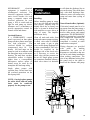
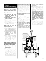
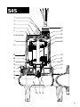
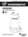
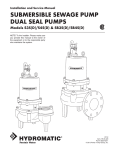
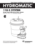
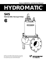
Pump Installation and Service Manual
HYDROMATIC
®
S4S
Submersible Sewage Pump
NOTE! To the installer: Please make sure you provide
this manual to the owner of the pumping equipment or to
the responsible party who maintains the system.
General
Information
Thank you for purchasing
your HYDROMATIC Pump. To
help insure years of trouble free
operation, please read the
following manual carefully.
Before Operation:
Read the following instructions
carefully. Reasonable care and
safe methods should be practiced.
Check
local
codes
and
requirements before installation.
Attention:
This manual contains important
information for the safe use of
this product. Read this manual
completely before using this
product and refer to it often for
continued safe product use.
DO NOT THROW AWAY OR
LOSE THIS MANUAL. Keep it
in a safe place so that you may
refer to it often.
Unpacking Pump:
Remove pump from carton. When
unpacking unit, check for
concealed damage. Claims for
damage must be made at the
receiving end through the delivery
carrier. Damage cannot be
processed from the factory.
WARNING: Before handling
these pumps and controls,
always disconnect the power
first. Do not smoke or use
sparkable electrical devices or
flames in a septic (gaseous) or
possible septic sump.
2
Pumps Not Operating or
In Storage:
Pumps with carbon ceramic seals
must have impellers manually
rotated (6 revolutions) after
setting non-operational for 3
months or longer and prior to
electrical start-up.
Pump:
The S3S submersible pumps are
supplied for 1 and 3 phase and for
200, 230, 460 or 575 volts. Pump
is supplied with 15 feet of power
cord. Longer cable lengths can be
furnished but must be specified at
time of order. Power cable is 4
wire with the green wire for
ground. Be sure green wire is
connected a ground lug in the
control panel and the control
panel must be connected to a
ground rod or ground wire from
supply service.
NOTE: All single phase pumps
require properly sized start
capacitor, start relay and run
capacitor in the panel.
Sump Level Control:
Sump level is controlled by
HYDROMATIC 3900 mercury
switch level controls. The 3900
level controls is a metal case
mercury switch sealed in a solid
polyurethane float. The float is
held in position by a weight
attached to the power cord above
the float. The cord supports the
float and is adjusted for height
from the surface.
Typical duplex systems use three
Floats; the lowest float turns the
pumps off, the next higher float
starts the lead pump, the next
higher float (override) starts the
lag pump. The pumps alternate
on successive cycles.
Two pumps operate together only
if sump level rises to the third or
override float. The override float
also brings on the second pump in
case of failure of the first pump.
Extra floats with appropriate
controls can be supplied for alarm
functions. Triplex systems use
four floats. The fourth highest
float brings on the second lag
pump. Three pumps operate
together only if sump level rises to
the fourth float (second override).
This float also brings on the third
pump in case of failure of either or
both of the first two pumps.
Alarm Controls:
The alarm float is usually set
above the override level so
the alarm will signal only if the
override level is exceeded.
However, some engineers prefer
to have the alarm float set below
the override level as it is possible
for one pump to fail and the other
pump to operate on the override
level with the sump level never
reaching the alarm level. This is
particularly true in cases of low
inflow capacity.
Electrical Control Panel:
It is recommended that the
HYDROMATIC control panel be
used with all pumps as proper
start components and pump
protection are furnished.
NOTE: All single phase pumps
require properly sized start
capacitor, start relay, and run
capacitor in the control panel.
IMPORTANT: If HYDROMATIC
control panel is not used and the
motor fails because of improper
components, the motor guarantee
is void.
HYDROMATIC
electrical
equipment is installed in a
weatherproof enclosure. The
electrical equipment includes a
main circuit breaker for each
pump, a magnetic starter with
overload protection for each
pump, a H-O-A switch and run
light for each pump, an electric
alternator and a transformer to
provide appropriate control for
control circuit and alarms.
Overload Heaters:
If a HYDROMATIC control
panel is not used, on three phase
pumps all three phases must have
over load protection.
The
overload should be ambient
compensated class 10.
The
heaters full load amps on the
pump be sized in accordance with
the nameplate amps on the motor
housing. The amp draw on these
submersible motors is slightly
higher than a corresponding
horsepower surface motor so
heaters must be sized by the
nameplate full load amp rating.
Single phase pumps with
capacitor start Circuit must have
the overload protection on the
black pump lead.
NOTE: On single phase pumps
the white, black, and red pump
leads must be connected
properly for the pump to run.
Pump
Installation
Installing:
Before installing pump in sump,
lay it on side and turn impeller
with fingers. Impeller may be
slightly stuck due to factory test
water so it must be broken loose
with small bar or screw driver in
edge of vanes. The impeller
should turn freely.
Clean all trash and sticks from
sump and connect pump to piping.
A check valve must be installed
on each pump. A gate or plug
valve in each pump discharge line
is also recommended. This valve
should be installed on the
discharge side of the check valve
so if necessary to service the
check valve, the line pressure can
be cut off. Single pump systems
are sometimes installed without a
check valve where it is desirable
to self-drain the discharge line to
prevent freezing. This can be done
only with short discharge lines.
Otherwise water will return to the
sump and cause short cycling of
the pump.
Nema 4 Junction Box (Optional):
If electrical control panel is to be
set remote from the pump sump, a
NEMA 4 junction box should be
used to make power and control
connections. The HYDROMATIC
NEMA 4 junction box is provided
with compression connectors for
sealing all wires. No sealing
compound is needed to make
connections waterproof.
Wiring diagrams are provided
with
panel
for
making
connections. An extra set of
diagrams are included so that one
set can be used during installation
when making connections. The
size of any additional wiring from
the pump cord to the panel is
based on the distance and pump
1
2
3
;;;;
;;;;;
;
;
;
;; ;;;;
;
;
;
;
;
;
;
;;
;
;;
; ; ;
;; ;;
; ;
4
28
5
24
27
6 (Not Shown)
26
7
8
;
23
22
9
10
25
19
;;
11
21
20
18
17
12
13
14
29 15 16
3
the snubber and readjusting
cord length.
In either simplex or duplex
system the lower or turn-off float
is set just above the top of volute
so that the volute will always be
submerged during the pumping
cycle. The second or lead/on float
higher is set at about 24 inches
above the lower turn-off control.
More distance between turn-on
and turn-off controls can be used
but sewage may become septic
and excessive solids may collect
for the pump to handle. A frequent
pumping cycle is recommended
for best operation.
If an alarm system is used, this
control is usually set about 6
inches above the override control.
Some engineers as described
previously prefer to have the
Pump
Installation
current. Double check that all
wiring is properly connected and
tight. NOTE: On single phase
pumps the white, black and red
pump wires must be connected
properly to the panel. Only the
proper sequence will work.
Installing
3900
Mercury
Switch Float:
The float cords are supported by a
mounting bracket that is attached
to sump wall or cover or to the
NEMA 4 junction box.
Cord snubbers are used to hold the
cord in place. Float level can be
changed at any time by loosening
alarm control set below the
override control.
Making Electrical Connections:
All electrical wiring must be in
accordance with local code, and
only competent electricians
should make the installations. A
set of prints is included for use in
making the installation. All wires
should be checked for grounds
with an ohmmeter or Megger
after the connections are made.
This is important, as one
grounded wire can cause
considerable trouble.
IMPORTANT: If equipment
is not properly wired and
protected as recommended, the
motor guarantee is void.
WIRE SIZE TABLE
FOR REMOTE LOCATION OF CONTROL PANEL LENGTHS ARE BASED ON A VOLTAGE DROP OF TWO PERCENT
Maximum length in feet from NEMA 4 junction box to control panel. For 3 phase only and for power lines only. All control wires can be = 14–16 or 18 gauge
wire. If power lines are for 460 or 575 volts insulation of control wires must be for this voltage if used in conduit with power lines.
Volts
Wire
Size
Motor
HP
230 460 575 230 460 575 230 460 575 230 460 575 230 460 575 230 460 575 230 460 575 230
3
3
3
5
5
700
5
71⁄2 71⁄2 71⁄2
10
10
10
50
220 340
15
15
15
20
20
20
25
25
25
30
30
12
110 450
90
370 580
10
180 720 1120 140
550 370
8
270 1100 1650 220
900 1400 175
700 1100 105
420 650
320 500
230 360
180
280
6
400 1600 2500 350 1400 2200 220
900 1400 150
600 930 105
420 650
90 370 570
360
560
320 500
370 1500 2300 230
950 1450 175
700 1100 140 550 850 125
500 800
100 400 620
4
90
360 560
2
35
460
575
35
35
230 360
90
360 560
370 1500 230 270 1100 1700 220 900 1400 210 820 1250 200 800 1250 150 600 930
*Special Junction Box required for wire sizes larger than #4.
NUMBER OF CONDUCTORS REQUIRED BETWEEN CONTROL PANEL
AND NEMA 4 JUNCTION BOX
System
Type
4
30
460 575 230
Number of
Control Wires
Number of
Power Lines
Number of
Ground Wires #8
Simplex
3
3
1
Simplex with Alarm
5
3
1
Duplex
5
6
1
Duplex With Alarm
7
6
1
Pump
Operations
Starting System:
1. Turn H-O-A switch to
off-position then turn on main
circuit breakers.
2. Open all discharge valves
and allow water to rise in
sump pump.
3. Turn H-O-A switch to Hand
position on one pump and
notice operation. If pump is
noisy and vibrates, rotation is
wrong. To change rotation
(3 phase), interchange any two
line leads to motor. DO
NOT INTERCHANGE MAIN
INCOMING LINES. If duplex
system, check second pump in
same manner.
4. Now set both H-O-A switches
to Auto position and allow
water to rise in sump until one
pump starts. Allow pump to
operate until level drops to
turn-off point.
5. Allow sump level to rise to
start other pump. Notice run
lights on panel; pumps should
alternate on each successive
cycle of operation.
6. Turn both H-O-A switches
to off position and allow
sump to fill to the override
control level.
7. Turn both switches to Auto
position and both pumps
should start and operate
together until level drops to
turn-off point.
8. Repeat
this
operation
cycle several times before
leaving job.
9. Check voltage when pumps are
operating and check the amp
draw of each pump. On 3
phase pumps, check amps on
each wire as sometimes a high
leg will exist. One leg can be
somewhat higher (5 to 10%)
without causing trouble. For
excessive voltage draw on one
leg, the Power Company
should be consulted.
Pump
Maintenance
As the motors are oil filled, no
lubrication or other maintenance
is required. The pump should be
lifted once every two years and
the oil drained from the motor
chamber to check for water.
Generally these pumps give
very reliable service and can be
expected to operate for years
on normal sewage pumping
without failure.
Lightning:
In some areas where considerable
lightning occurs, it is recommended
that a lightning arrestor be
installed at the control panel.
Complete data on lightning
arrestors and cost is available
from the factory. Lightning arrestors
are good insurance against
damage to an expensive motor.
Servicing Instructions:
IMPORTANT:
Read
all
instructions before replacing
any parts.
WARNING: Before handling
these pumps and controls,
always
disconnect
the
power first.
Do not smoke or use sparkable
electrical devices or flames in a
septic (gaseous) or possible
septic sump.
Field Service On Motor:
All submersible motors can be
serviced (out of warranty) in the
field by any reliable motor
service shop. Any pump (in
warranty) must be returned to the
factory for service or repaired in
an authorized HYDROMATIC
service center. Charges will not
be allowed if (in warranty) pump
is not taken to a motor repair
shop that is not an authorized
HYDROMATIC service center.
When field service is performed
on a pump, these instructions
should be carefully followed.
Replacing Stator:
If motor winding is burned or
shorted, it can be rewound or
replaced with new factory wound
stator. Refer to sectional drawing
of pump and motor and use
following steps to remove and
replace stator.
1. If stator only is damaged, it
may not be necessary to
completely dismantle pump as
stator and housing can be
lifted from pump without
disturbing seals or bearings.
2. Drain all oil from upper
housing. If oil is clean and no
water is present, seals can
be considered satisfactory
to reuse.
3. After chamber is drained,
remove hold down bolts and
lift off. Use care in lifting.
4. Set assembly on bench and
remove cord cap assembly.
When this is lifted off,
connection wires to motor will
be exposed. These wires will
probably be burned but each
wire is tagged with a metal
marker giving wire number.
Cut the wires.
5. If the leads to the cord cap
assembly are burned, the
assembly must be replaced.
5
Pump
Maintenance
6. After stator retaining ring is
removed, turn housing upright
and bump on hardwood
blocks. This should jar the
stator loose and allow it to
drop out.
7. Thoroughly clean housing
before replacing new stator.
Replace stator and make all
wire connections to cord cap
assembly before replacing
housing on pump. This is
important as leads must be
tucked behind the windings
by using hands up through
rotor core.
IMPORTANT:
Use
only
compression type insulated
connectors on the wires. Do not
tape leads as oil will deteriorate
the tape and cause damage to
stator and bearings.
8. Check top bearing. If clean and
does not turn rough, bearings
can be reused and it is not
necessary to completely
dismantle pump to change
bearings. If bearings are
damaged with dirt or heat, they
must be replaced. See
additional instructions on
replacing seals and bearings.
Remember to reinstall the
upper bearing load spring.
9. Replace stator housing onto
seal chamber and bolt in place.
Be sure O-ring seal has been
replaced. If O-ring is nicked or
cut, replace the new rings. This
applies to all O-rings used
in assembly.
10.After
all
leads
are
reconnected, make a high
voltage ground test on each
6
wire. The only wire that should
show ground is the green
power lead.
11.Refill motor chamber with
oil. Use only high grade
transformer oil or regular
HYDROMATIC
special
submersible oil. Fill chamber
until oil covers top of
windings. Leave air space in
top for expansion. Use
permatex on plug threads.
Replacing Seals And Bearings
1. Drain all oil from motor
chamber as described.
2. Remove bolts that hold motor
housing to pump housing.
Remove screws holding seal
plate to motor housing.
3. Lift rotating assembly (rotor,
shaft and impeller) from pump
case and place horizontally on
bench. With hardwood block,
tap end of impeller to loosen
from shaft.
4. Shaft sleeves are not used.
5. Remove lower seal spring and
pry out seal with screwdriver.
6. Use bearing puller to remove
bearings. Replace with new
bearings. Press only on inner
race of bearing when
replacing. Pressing on outer
race can damage the bearing.
Bearings are standard size
that can be obtained from
any bearing supply house
or can be obtained from
HYDROMATIC factory.
7. IMPORTANT: Do not use
any of the old seal parts.
Replace with all new seals.
8. Thoroughly clean all castings
before replacing seals. One
grain of dirt between the seal
faces can cause failure.
Examine all O-rings for nicks
before reusing.
9. Use Locktite on socket head
locking screw in end of shaft.
10.Before refilling chamber with
oil, air test as described above.
11.Refill chamber with oil as
described above.
12.Always check all leads with
high voltage or with megger
for grounds before operating
the pump.
Fig. 1
CONNECTION DIAGRAM FOR LEADS IN
MOTOR AND CONNECTION BOX
(Y) WYE MOTOR CONNECTIONS
230 VOLTS
460 VOLTS
6
5
4
6
5
4
9
8
7
9
8
7
3
L1
2
1
L3 GREEN
3
2
1
L2
L1
L2
L3 GREEN
Pump
Troubleshooting
Below is a list of common
problems and the probable causes:
Pump will not start
1. No power to the motor.
Check for blown fuse
or tripped circuit.
2. Hand-off-auto switch may be
in the off position.
3. Control circuit transformer
fuse may be blown.
4. Overload relay on starter may
be tripped. Push to reset.
Pump will not start and
overload heaters trip
1. Turn off power and check
motor leads with megger or
ohmmeter for possible ground.
2. Check resistance of motor
windings. All 3 phases
should show close to the
same reading.
3. If no grounds exist and the
motor windings check O.K.,
remove pump from sump
0and check for clogged or
blocked impeller.
Pump runs but will not shut off
1. Pump may be air locked. Turn
pump off and let set for
several minutes then restart.
2. Lower float control may be
hung-up in the closed position.
Check in sump to be sure
control is free.
3. Selector switch may be in the
Hand position.
Pump does not deliver proper
capacity
1. Discharge gate valve may
be partially closed or
partially clogged.
2. Check valve may be partially
clogged. Raise level up and
down to clear.
3. Pump may be running in
wrong direction. Low speed
pumps can operate in reverse
1
2
3
;;;;
;;;;;
;
;
;
;;; ;;
;;
;
;
;
;
;;
;
;
;
;; ;;
; ;
4
28
5
24
27
6 (Not Shown)
26
7
8
Pump operates with selector
switch in hand position but will
not operate in auto position
1. This indicates trouble in the
float level control or the
alternator relay.
2. To check for defective float
control put selector switch in
auto position and turn off main
power. Put a jumper wire on
terminal strip. Turn on power
and if pump starts, trouble is in
float control. Replace control.
direction without much noise
or vibration.
4. Discharge head may be too
high. Check total head with
gauge
when
pump
is
operating. Total head is
discharge gauge pressure
converted to feet plus vertical
height from water level in
sump to center line of pressure
gauge installed in discharge
line. Gauge should be installed
on pump side of all valves.
Multiply gauge pressure in
pounds by 2.31 to get head
in feet.
5. If pump has been in service for
some time and capacity falls
off, remove pump and check
for wear or clogged impeller.
;
25
23
19
22
21
9
20
10
18
11
17
12
13
14
29 15 16
7
S4S
Parts List
ORDERING REPLACEMENT PARTS: Product improvements are made from time to time. The latest part design will be furnished
as long as it is interchangeable with the old part.When ordering replacement parts, always furnish the following information: (1)
pump serial number, (2) pump model and size, (3) part description, (4) part number, (5) impeller diameter (if ordering impeller),
(6) quantity required, and (7) shipping instructions.
Ref.
No.
Part
No.
1
00589-002-1
2
Part
Description
Qty.
Ref.
No.
Part
No.
Part
Description
Eyebolt
2
18
00150-021-1
O-Ring
00178-004-1
Capscrew
2
19
00517-007-1
3
13425-023-1
Nameplate
1
20
4
04580-001-1
Drive Screw
4
5
00087-004-1
Pipe Plug
6
01032-003-1
Nut-Hex- 3/8-16 SST
7
00064-003-1
Load Spring
8
00065-021-1
9
10
Qty.
Part
No.
Part
Description
Qty.
1
14713-003-1
Stator (71⁄2HP 3ø 230/460V)
R
1
Capscrew
4
14713-203-1
Stator (71⁄2HP 3ø 200V)
R
1
00995-008-1
Lockwasher
4
14713-603-1
Stator (71⁄2HP 3ø 575V)
R
1
21
00299-002-1
Stator Retaining Ring
1
02577-000-1
Wire Connector
As Recq.
1
22
05454-001-1
Roll Pin
1
00282-001-1
Wire Connector (14 & 16 wire size)
As Recq.
2
23
13391-000-2
Motor Housing
1
01006-001-1
Wire Connector (10 & 12 wire size)
As Recq.
R
1
24
00834-015-1
O-Ring
06461-023-5
Cord Cap Assy. 15' Single 10/4
1
Upper Bearing
R
1
25
10922-024-5
Rotor w/Shaft (3HP 1ø)
1
06461-024-5
Cord Cap Assy. 30' Single 10/4
1
00065-018-1
Lower Bearing
R
1
01329-025-5
Rotor w/Shaft (All 3ø)
1
06461-002-5
Cord Cap Assy. 15' Single 12/4
1
04916-000-1
Shaft Seal
S
1
12750-023-5
Rotor w/Shaft (5HP 1ø)
1
06461-014-5
Cord Cap Assy. 30' Single 12/4
1
04916-001-1
Shaft Seal (Carbide) Opt
C
1
14698-003-1
Stator (3HP 1ø 230V)
R
1
10418-000-5
Cord Cap Assy. 15' Single 8/4
1
11
00239-016-1
Capscrew
4
14699-003-1
Stator (3HP 3ø 230/460V)
R
1
10418-002-5
Cord Cap Assy. 30' Single 8/4
1
12
01130-003-1
Machine Screw (Flat Head)
4
14699-203-1
Stator (3HP 3ø 200V)
R
1
09978-007-2
Impeller (3HP)
1
13
09995-000-2
Volute Case
1
14699-603-1
Stator (3HP 3ø 575V)
R
1
09978-008-2
Impeller (5HP)
1
14
10108-000-1
Impeller Washer
1
14711-003-1
Stator (5HP 1ø 230V)
R
1
09978-009-2
Impeller (71⁄2HP)
1
15
00238-001-1
Impeller Capscrew
1
14712-003-1
Stator (5HP 3ø 230/460V)
R
1
51700-061-7
Seal Kit
16
08908-002-1
Key
1
14712-203-1
Stator (5HP 3ø 200V)
R
1
51700-361-7
Carbide Seal Kit
17
09996-002-2
Seal Plate
1
14712-603-1
Stator (5HP 3ø 575V)
R
1
*
26
SC
Ref.
No.
SC
1
27
28
29
R
Rebuild Kit
Notes: S — Parts in Seal Kit C — Parts in Carbide Seal Kit I — Parts in Impeller Kit R — Parts in Rebuild Kit *Consult Factory
8
S4S
1
2
3
;;;;
;;;
;;;
;
;
;;;;;;;
;;
;;;
;;
;
;
;
;
;;;
;
;
;
;
;
;;;;;
;;
;;;;
;;;
;; ;;;
;
;; ;;
; ;
4
28
5
24
27
6 (Not Shown)
26
7
8
;;
;;
;;
;;
25
23
19
22
21
9
10
11
12
;; ;
;;
;;
;
20
18
17
13
14
29 15 16
9
WARRANTY
Hydromatic Pumps, Inc. warrants to the original purchaser of each Hydromatic product(s) that any part
thereof which proves to be defective in material or workmanship within one year from date of installation or
18 months from manufacture date, whichever comes first, will be replaced at no charge with a new or
remanufactured part, F.O.B. factory. Purchaser shall assume all responsibility and expense from removal,
reinstallation and freight. Any item(s) designated as manufactured by others shall be covered only by the
express warranty of the manufacturer thereof. This warranty does not apply to damage resulting from
accident, alteration, design, misuse or abuse. The pump must be installed, operated and maintained in
accordance with the published instructions of the appropriate Installation & Service Manual.
All dual seal non-clogs and 3–5 HP grinders must have seal failure and heat sensors attached and functional
for Warranty to be in effect. If a seal failure should occur, Hydromatic Pumps will cover only the lower seal
and labor thereof. Labor based on Authorized Service Center contract allowance. If the heat sensor is not
attached and functional, Warranty is void. If the seal failure sensor is not attached and functional, Warranty
is void.
If the material furnished to the Buyer shall fail to conform to this contract or to any of the terms of this
written warranty, Hydromatic Pumps, Inc. shall replace such nonconforming material at the original point
of delivery and shall furnish instruction for its disposition. Any transportation charges involved in such
disposition shall be for the Buyer’s account. The Buyer’s exclusive and sole remedy on account or in respect
of the furnishing of material that does not conform to this contract or to this written warranty, shall be to
secure replacement thereof as aforesaid. Hydromatic Pumps, Inc. shall not in any event be liable for the cost
of any labor expended on any such material or for any incidental or consequential damages to anyone by
reason of the fact that such material does not conform to this contract or to this written warranty.
ALL IMPLIED WARRANTIES, INCLUDING THE IMPLIED WARRANTY OF MERCHANTABILITY
AND THE IMPLIED WARRANTY OF FITNESS FOR A PARTICULAR PURPOSE, ARE DISCLAIMED
TO THE SAME EXTENT AS THE EXPRESS WARRANTY CONTAINED HEREIN. Some states do not
allow limitations on how long an implied warranty lasts, so the above limitation may not apply to you.
MANUFACTURER EXPRESSLY DISCLAIMS AND EXCLUDES ANY LIABILITY FOR
CONSEQUENTIAL OR INCIDENTAL DAMAGES FOR BREACH OF ANY EXPRESS OR IMPLIED
WARRANTY ARISING IN CONNECTION WITH THIS PRODUCT, INCLUDING WITHOUT
LIMITATION, WHETHER IN TORT, NEGLIGENCE, STRICT LIABILITY CONTRACT OR
OTHERWISE. Some States do not allow the exclusion or limitation of incidental or consequential damages,
so the above limitation or exclusion may not apply to you. This warranty gives you specific legal rights, and
you may also have other rights which vary from State to State.
© 1999 Hydromatic®, Ashland, Ohio. All Rights Reserved.
– Your Authorized Local Distributor –
1840 Baney Road Ashland, Ohio 44805
Tel: 419-289-3042 Fax: 419-281-4087
www.hydromatic.com ISO 9001 Certified
Part# 5625-321-1
Item# E-03-321 5M 1/01