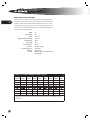
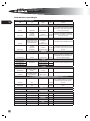
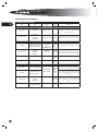
1
SPECS & MAINTENANCE Forward Engine General Specification, Chassis Specifications are for standard equipment, unless otherwise stated. 21 Alternator 200 Amp Bosch, 12 Volt, High-Output (standard). 185, 270 or 320 amp Leece Neville, 12 Volt, High-Output (optional) on: • FE with Cat C7 engines. All American FE Alternator Output @ Idle 200 amp Bosch (standard) ENGINE COLD (C) Caterpillar C7 159 amps 185 amp Leece Neville (optional) ENGINE COLD (C) Caterpillar C7 161 amps 270 amp Leece Neville (optional) ENGINE COLD (C) Caterpillar C7 200 amps 320 amp Leece Neville (optional) ENGINE COLD (C) Caterpillar C7 225 amps HOT (C) 136 amps HOT (C) 139 amps HOT (C) 175 amps HOT (C) 178 amps Axle, Front The front axle model is Hendrickson Steertek, with a Gross Axle Weight Rating of 13,200 lbs. capacity. Synthetic oil bearing lubrication and windowed hubcaps. Axle, Rear Meritor single reduction speed with synthetic bearing lubrication. Standard model is RS21-145; 21,000 lb GAWR; 5.29:1 reduction ratio. All American FE may be equipped with optional models depending upon GVWR and reduction ratio, suspension, and/ or brakes options: Meritor Model RS19-144 RS21-145 RC23-160 RS23-160 GAWR Details 19,000 lbs 21,000 lbs Standard. 23,000 lbs 23,000 lbs L SERVICE MANUAL 22 Batteries Two 8D, 12V/225 AMP/2800 CCA combined. 4/0 gauge battery cables are included. Battery cables positive and negative are loomed complete from terminal end to terminal end. Enclosed in large locking heavy duty battery compartment. Braking System Service Brakes, Hydraulic. Both front and rear systems have 15” diameter x 1.438” thick rotor, Meritor Quadraulic hydraulic brakes at all wheels. 70MM dual system 4 pistons per caliper. Self-adjusting design. Meritor ABS. Dustshields are included. Emergency/Parking (Units with Hydraulic Brakes). Standard park brake, installed on All American Forward Engine buses with hydraulic brakes, is an internal expanding, transmission mounted, 9” diameter x 3” wide, cable-actuated assembly, operated by a control lever at the driver’s left. Service Brakes, Air. Meritor air actuated drum brakes are optional on most All American Forward Engine units, and are required by certain engine options and/or GVWRs. (See Engine for more info.) All American Forward Engine units equipped with air brakes have 6” Meritor Q-Plus linings on front; and either 7” or 8.62” lining on rear, depending upon GVRW. Emergency/Parking (Units with Air Brakes). All American Forward Engine buses equipped with air brakes employ dual-chamber air brakes in the rear, which incorporate a spring brake in the outer chamber. Bumpers Front and rear bumpers are die-formed, 12” high with 90° flanges, top and bottom. Front. One-piece 1/4” thick steel plate with step holes for cleaning windshield. Rear. One-piece 3/16” thick steel plate with 14” wraparound at corners and double “A” frame bracing. Controls Electronic operated throttle, hydraulic brake pedal, hand applied parking brake with warning light, transmission selector, dimmer switch, instrument panel rheostat-controlled lighting and key-type starter switch. Cooling System Engine. Charge air and down-flow radiator mounted in tandem at vehicle front. 25” dia. nylon cooling fan with nine blades equipped with a fully-on or fully-off electromagnetic fan clutch driven by polyvee fan belt with spring loaded tensioner. Fan controlled by engine ECM. Black rubber coolant hose with constant torque clamps. Transmission. Transmission fluid cooled by 2100 BTU/minute heat exchanger external to radiator. Long-life 55/45 Coolant mix provides anti-freeze protection to -40° F Drive Line Spicer SPL 70 or SPL 100 with protective guard around shaft. L SPECS & MAINTENANCE Engine Forward Engine All Americans are built with Caterpillar C7 or Cummins ISB engines. Caterpillar C7 series turbo diesel in one of several horsepower/torque configurations shown in the table below. Includes electric fan clutch and 500W / 120V AC internal engine block heater (serves as a heater start aid). Includes a power cord. All American Forward Engine Caterpillar C7 Configurations Engine Horsepower @ RPM Torque @ RPM Caterpillar C7 7.2L Turbo Diesel 190/520 (standard) 207@2300 (195@2500 Governed) 520 ft lb @1440 Caterpillar C7 7.2L Turbo Diesel 210/520 210@2300 (202@2500 Governed) 520 ft lb @1440 Caterpillar C7 7.2L Turbo Diesel 230/540 230@2200 (214@2500 Governed) 540 ft lb @1440 Caterpillar C7 7.2L Turbo Diesel 230/660 230@2200 (221@2500 Governed) 660 ft lb @1440 Caterpillar C7 7.2L Turbo Diesel 250/660 250@2200 (240@2500 Governed) 660 ft lb @1440 Caterpillar C7 7.2L Turbo Diesel 275/800 275@2200 (264@2400 Governed) 660 ft lb @1440 23 Transmission Brakes Allison PTS 2500 Hydraulic Brakes or Air Brakes Allison PTS 3000 5 speed Air Brakes Exhaust Stainless steel muffler. 4” O.D. 16 gauge aluminized steel tailpipe exits through bumper, road side. Tailpipe is 0 to 1/2” beyond bumper. Wide band exhaust clamps used at all joints. Floor, Driver Area Raised 2” above floor, has .62” plywood with .19” ribbed rubber floor cover. Frame Main Frame. Dual “C” channels, 9.63” high with 3” flanges made of .25 thick, 50,000 PSI steel, Section Modulus = 10.1 in.cu. Sub-Frame. Dual “C” channels, 9” high with 2 3/8” flanges made of .25 thick, 50,000 PSI steel, Section Modulus = 8.4 in.cu. Fasteners. All permanent fixtures on frame are attached with hi-tensile strength Huck-Spin fasteners with swaged lock nuts. Fuel System 100 gallon capacity (available only with: 211, 232 wheelbase) or 60 gallon capacity (available only with: 141, 169, 190 wheelbase). Aluminized steel safety tank mounted between frame rails. Includes a sender inspection plate and right hand fill opening with spring loaded locking door. Primary fuel filter/water separator is a Racor, 30 micron filter, with see-thru bowl and self-venting drain. Filter head includes integral check valve on inlet side, 200 watt heater. Secondary spin-on fuel filter mounted on engine. Fuel pump mounted on engine. L SERVICE MANUAL 24 Horn Electrical dual with non-glare horn button emblem. Backing Safety Horn. Activated whenever the bus is shifted into reverse. Sounds between 87 and 112 db, automatically adjusting itself depending on the ambient noise level in the proximity of the alarm Instruments Gauges. Speedometer with English major and metric minor; seven digit Odometer; resettable Trip Odometer; Tachometer; seven digit engine Hourmeter; Oil Pressure; Voltmeter; Fuel Level; Coolant Temperature; Front Brake Pressure; Rear Brake Pressure; digital Clock; Panel Dimmer slide; Ammeter. Gauges have automatic self-test at power up. Needles sweep while display indicates “TEST”. LED Telltale Warnings / Indicators. Right and left directional (green); high beam indicator (blue); Service Brake Applied (red); Park Brake Applied (red); ABS Active (amber); Stop Engine (red); Service Engine Soon (amber); Check Transmission (Red); Low Coolant Level (Amber). Dash Mounted Switches. Headlights with Parking Light position; incremental High Idle with Low Idle Return; Cruise Control, includes two dash switches: Cruise Control On/Off ; Cruise Set/Resume. Steering Full power Ross TAS-65 integral unit with 20.4 to 1 ratio; with gear driven hydraulic pump. Tilt telescoping steering column with 18” diameter, two-spoke, padded steering wheel. Suspension, Front Front Spring Suspension (Standard). Hendrickson SofTek. 4” x 56”, single stage, three-leaf parabolic leaves with up-turned eyes, 1.25” diameter pins in graphite impregnated steel backed bronze bushings with urethane seals at each end. 7,300 lbs. capacity each at ground. One inch spacer block between the front spring and the axle. Direct acting, 1.75 diameter bore double-action piston type Monroe shock absorbers with long life bonded bushings. Front Air Suspension (Optional). Hendrickson AirTek. 14,600 lb rated. Integrated front air suspension and steer axle that work together to form an integrated torsion system delivering superb ride stability and handling characteristics with reduced weight and maintenance. Suspension, Rear Rear Spring Suspension (Standard). Hendrickson Softek. 3” x 52” semi-elliptic, progressive, variable rate, 13-leaf slipper springs, Capacity rating varies depending upon wheelbase. Maintenance free, rubber bushed radius leaf permits axle adjustment for dog tracking. Monroe direct acting, 1.75 diameter bore double-action piston type shock absorbers with long life bonded bushings. L SPECS & Rear Air Suspension (Optional). Hendrickson Comfort Air. Trailing arm design with 2 heavy-duty rolling lobe air springs. Quick-align feature for axle dog track adjustment. Sachs 1.375” diameter bore shock absorbers, with bonded eye bushings. MAINTENANCE 25 Tires Goodyear or Michelin 11R 22.5 H ply tubeless XZE Highway Tread. Tow Hooks Two front and rear, tow hooks are frame mounted. Transmission Allison PTS 2200, 2500, and 3000 Series transmission, 5 Forward speeds- 1 reverse. 33,000 lbs GVW. Synthetic transmission fluid is standard. Wheels Aluminum and Hub Piloted steel 10 stud disc wheels, single front, dual rear, 22.5 x 8.25 rims. L SERVICE MANUAL Forward Engine General Specification, Body 26 Access Panels Interior. Hinged access door on engine hood for access for routine daily engine inspection & service. Exterior. All access panels include keyed locked latches Electrical Terminal. 27” x 16” hinged door located exterior below driver’s windows for access to body electrical junction, terminals and circuit breakers. Door has retainer to hold in open position. Front Grill. Hinges downward for service access to fill and sight glass Right Front. 19” x 15 ½” hinged door provides access to heater air intake screen, air restriction indicator and wiper motor. Left Front. 19” x 15 ½” hinged door permits access to windshield washer reservoir, power steering reservoir and wiper motor. Compartments Battery. Enclosed compartment 23.63” x 24.00” with rolling tray. Includes two retaining pins with cable to secure the tray in a closed position. Hinged door with recessed locking Paddle Handle latch. Located on left side behind front wheel well. Emergency. Provides key locking compartment for storing certain emergency equipment located in upper front. Key lock is equipped with switch and wired to buzzer to indicate that compartment is locked when ignition is turned on. Glove Box. 11” x 6 ½” door above windshield on right side with door and latch. Doors Rear Center Emergency Door. 37.7” wide x 52.5” high opening. Latching mechanism includes a single-point bar lock with inside handle and guard, and an outside 6” chrome-plated recessed handle. Door includes upper and lower tempered green tinted safety glass. Doors are identified as “EMERGENCY DOOR”, 2” black letters, above the door, on the outside of the bus. Includes Emergency door arrows inside and outside 6” long x ¾” wide black arrow on the emergency door near the handles to indicate direction of turn for opening. On the outside, arrow points up and approximately 45° inboard of door; inside, the arrow points up. Arrows are in addition to standard ”OPERATING INSTRUCTIONS” decal. A DOT warning buzzer activated by movement of the door latching mechanism is included. A 5” black fire-block upholstery header pad is included. A telescopic prop support attached to the top inside of the emergency door to hold it open at approx. 95°. Slide-bolt security latch prevents door from being opened from the outside when engaged. Bolt is connected to an interlock assembly which prevents engine starting when door is locked. If the lock is activated after the engine is running, an audible alarm is sounded in the driver’s area. Outward Opening Entrance Door, Manual Operation. Two panels open outward and close to seal against outside edge of lower step. Includes laminated green tinted glass. Ball bearing suspended for ease of operation and wear resistance. A Manual locking mechanism is built into the forward outward opening door assembly. This will disconnect the door from the manual control rod, and allow the door to be L SPECS & opened from the outside of the bus. The latch located in the front door panel and accessible from outside the bus is lockable with the LL25 key. 4” wide black fire-block upholstery header pad over the door opening inside the bus. Stainless steel assist rail at the rear of the stepwell. Manual over-center control with an automatic latching device built into the handle for holding the door closed. Driver manually disengages the latch as the door is opened. Pivot bearings are oil-impregnated bronze. MAINTENANCE 27 Electrical Power Socket, Accessory With Cap. Provides 12 volt power socket for connecting electrical accessories such as cellular phones, CB radios, etc. Only one per vehicle. Fans Driver’s Auxilliary Fans. 6” fan mounted to wire molding, located in the upper left, above driver’s window. 6” fan mounted to windshield header, center of body. Floor Aisle. ⁄” thick ribbed gray rubber in aisles and at entrance aisle area. Aluminum Aisle trim over joint in floor covering, full length of body. Underseats. ⁄” thick smooth gray rubber. Galvanized steel cove molding at wall. Wheelhousing. Molded black smooth rubber with galvanized steel trim. Underfloor. ⁄” AB marine grade plywood, attached with screws. Headroom Full 74”, over floor covering and ⁄” plywood floor, measured at center aisle. Heater/defroster Goodyear Hi-Miler heater hose with constant torque clamps at all joints. Includes all heater hoses and hose clamps within the body heater system. Electrically controlled water regulating valve. Front Heater/Defroster. 90,000 BTU with washable air filter. Driver selects air flow up to 100% for defrosting windshield, driver’s window and entrance door as conditions require. Auxiliary. 12,000 BTU, two speed heater under driver seat left side. Dual ball type, heater cut-off valves isolate system from engine and radiator when necessary. Insulation The roof, sides, front and rear (including corners & bows) are insulated with 1 ½” thick material providing an “R” value of 5.75. Driver’s left hand close-out panel is insulated inside and outside. Lettering 3M Diamond Grade “SCHOOL BUS” 8” black vinyl letters on yellow reflective tape on roof caps, front and rear. BLBS lettering and Bus numbers. L SERVICE MANUAL 28 Lights Back-Up. Two 5” clear right and left rear. Clearance. Two amber front and two red rear single with shields. Switch operates clearance, cluster and side marker lights. Cluster. Three amber front and three red rear with shields. Daytime Running. Head lamps, tail, license plate, parking, clearance & marker lights activated when engine is running. Directionals. 7” Front and rear, two plain amber front, two amber rear. Sealed, shock mounted, side directionals mounted at front belt line area Dome. 15 Candlepower. Two rows equally spaced at center over aisle. Two switches, front and rear. Separate switch to control the last two dome lights of the dual row. Driver’s dome light activated with separate switch. Headlights. Four rectangular, Halogen single-sealed beam. Parking. 4” Amber, right and left front Side Marker. Amber right and left intermediate side marker lights. Stepwell.14 Candlepower. Wired to operate with ID lights with entrance door open. Stop and Tail. Two combination lights, 4” right and left rear license panel in combination with 7” stop and tail lights with clear red lens. Warning System. Weldon 8 light sequential system with dual hoods. Mirrors, Exterior All exterior mirrors will be heated. Heat is controlled by an on/off switch. Crossview. A Rosco “Mini-Hawkeye” crossview mirror system is provided to allow a seated driver to view pedestrians while the bus is stopped. The crossview mirror system is comprised of a 10.8” x 12.5” elliptical mirror with tinted upper portion to reduce glare. The mirror mounting posts are attached to the front cowls, and feature a breakaway pivot to reduce damage in the event of accidental contact. The crossview mirror system allows for viewing all areas along the front and sides of the bus which are not visible by direct view. Rearview. The Rosco “Avia” rearview mirror system is designed to provide a view of the roadway to the rear, as well as a view of the ground along both sides of the bus. The Rearview mirror system is comprised of a 9” x 17” oval heads each containing 74 sq. in. flat and a 38 sq. in. convex. The right rearview mirrors are located so as to be visible through the wiped area of the windshield. The left rearview mirrors are located so as to be visible through the driver’s window. Rearview mirrors on both right and left sides feature spring breakaway pivots and are adjustable without tools. Mirrors. Interior Rearview. 6” x 30” with ⁄” clear safety glass laminated to steel backing plate. Mirror has 1 ¾” radius rounded corners. Perimeter of mirror is edged with ⁄” diameter rubber padding. The interior rearview mirror is installed above the seated driver on the front upper inner panel, and is designed to provide a clear view of the interior of the vehicle and of the roadway to the rear. L SPECS & Mud Flaps Front. Metal guard forward of front axle; left side. Mudflaps to full length, installed behind front wheels. Black rubber fenders. Rear. 23 x 30” mudflaps; both sides (without logo and with extensions included). Black rubber fenders. MAINTENANCE 29 Paint Exterior. National school bus yellow with black trim and black bumpers. OEM, heat cured, polyurethane. Interior. Astro White, hot sprayed-on baked enamel, except aluminized inner side panels. Seat frames, heaters and trim are Black, switch consoles and dash medium gray. Rust Proofing. Body parts thoroughly rust-proofed after fabrication and before assembly. Undercoat. Underside of body floor, skirt and wheelhousings thoroughly undercoated prior to body mount to insure best coverage and maximum corrosion resistance. Undercoat material offers optimum corrosion protection. Roof Cap. A Minimum area of 3” band of black background is painted around warning lights, front and rear. Panels, Exterior Body.19 ¾” Skirt panels. Outside side panels are constructed of 16 gauge smooth steel. Side panels extend from below the side windows to a distance of 19 ¾” below the floor. Rear corner panels are constructed of 20 gauge steel and include a license plate emboss, both right and left. Front cowl panels are16 gauge steel. Roof. The front roof cap is formed from 18 gauge steel. The rear roof cap is formed from 20 gauge steel. Roof sheets are constructed of 20 gauge steel and span the entire width of the bus (window header to window header). Roof sheets include an embossed rain visor over side windows. Floor. 14 gauge steel, reinforced with full width “U” channel cross members. All riveted floor joints are reinforced with full width ⁄” x 1 ½” x 2” structural steel angles. Panels, Interior A removable 18 gauge steel front upper panel provides access to the front roof cap area. Wire molding over window provides easy access to body wiring harness. Textured aluminized fully hemmed steel inside side panels extend from the window sill down to the floor gusset seat ledge, for the entire length of the body on both left and right sides. Perforated acoustic headlining panels, spanning the entire width of the bus (window header to window header), are constructed of 22 gauge steel and are double-hemmed to provide additional joint strength. Radio AM/FM/PA/CD, console mounted with 8 deluxe speaker system. Wiring for two way radio system. (Two way radio is not included.) L SERVICE MANUAL 30 Reflectors Standard reflectors include: • Two 3” amber mounted on side of body near front. • Two 3” red mounted on side of body near rear. • Two 3” red, mounted on rear of body. • Two 3” amber right and left intermediate side reflectors. Reflective Tape. 3M Diamond Grade. 1” minimum width strip surrounds each emergency exit, 1 ¾” wide rear structure, and 2” wide strip on each side of unit at approximately floor level. Front and rear roof cap, with Black 8” “SCHOOL BUS” lettering. Canada. 1” wide strip of yellow reflective vinyl on each side of the bus, above the passenger windows. Vertical 1” strips of yellow reflective vinyl at both the rear bow and front corner post, both sides of the bus. Rubrails Four double-ribbed 16 gauge steel applied rubrails are installed along both sides of the body. The rubrails are installed as follows: One below side windows; one at seat (passenger) level; one near the floor level; one at the bottom of the skirt. The window rail extends from the front bow on the right side, or the front cowl post on the left side to the rear corner radius. The seat rail extends from the front bow, both right and left around the rear corner radius. The floor rail extends from the front bow, both right and left, to the rear corner radius. The skirt rail extends from the front bow on the right side, or the front cowl post on the left side, to the rear bumper (interrupted by wheelhousing cut-out). Bumper rubrail installed below rear emergency door, immediately above the rear bumper. Safety Equipment Triangular Warning Device floor mounted. Seat belt cutter included as standard equipment when lift door is ordered. Seats Driver’s. Bostrom Routemaster black vinyl with gray fabric insert, high back pedestal type with seven inch fore and aft travel and five inch vertical adjustment. Seat belt is three-point, floor mounted anti-cinch emergency locking retractor. Adjustable pillar loop provides approximately 7 ½” vertical adjustment at the shoulder belt top mount. Driver’s armrest to left of driver on rear portion of switch panel. Passenger Seat Upholstery. All Passenger seats are optional and will be upholstered in Fire Block vinyl, solid gray. Stepwell Three-step, 24 ¾” depth stainless steel. Step treads with white abrasive stripe inserted and bonded into a recessed area. 3” white abrasive wear plate is located at the floor level step of the entrance door. Includes a stainless steel assist rail at the rear of stepwell. L SPECS & Stop Arm An electric operated High Intensity Reflective octagonal stop arm, red with a white border and 6” high lettering. “STOP” or “ARRETT” on both sides. Includes red LED cluster lights over and under the word “STOP” visible from both sides. MAINTENANCE 31 Sun Visor Transparent dark green tint 6.5” x 30” smooth edge plastic. Located in front of driver. Adjustable vertically on two arms pivoted at ends of visor and at anchor points on windshield header. Switch Panel Mounted left and right of driver with rocker-type self illuminated switches for electrical equipment. Brightness of illumination is controlled by a separate dimmer switch located in the left switch panel. Ventilation Air Intake. Heater intake on right front below windshield level is electrically controlled. Manual driver’s fresh air vent on left by driver’s feet. Static Vent. Static non-closing type in front roof. Windows Driver’s. Double sliding aluminum sash with security fastener for locking both sashes, laminated green tinted glass. Side. 9” Split Sash, tempered tinted glass in aluminum frame, 9” clear opening when lowered. Rear Vision. Tinted tempered. Windshield The windshield consists of four separate pieces of flat shaded safety plate glass. To facilitate cleaning of the windshield from the outside, there are non-glare, black, grip handles above the windshield on each side of the vehicle with steps in the bumper. Windshield Wipers Electric, intermittent single switch, parallelogram type, bottom mounted with remote control, non-glare arms and blades. Electric windshield washer with hard plastic 6 quart capacity reservoir located behind right front access door, washer outlets mounted on wiper arms. Wiring Color- and number-coded in molding above windows for access to harness without removing windows. Body wiring protected by automatic resetting circuit breakers, located in easy access exterior wire terminal junction under driver’s window. L SERVICE MANUAL Rear Engine General Specification, Chassis Specifications are for standard equipment, unless otherwise stated. 32 Alternator 200 Amp Bosch, 12 Volt, High-Output (standard). 185, 270 or 320 amp Leece Neville, 12 Volt, High-Output (optional) on All American Rear Engine with Cummins ISC or Cat C7 engines. All American RE Alternator Output @ Idle 200 amp Bosch (standard) ENGINE COLD (C) Cummins ISB 158 amps Cummins ISC 156 amps HOT (C) 135 amps 133 amps Caterpillar C7 159 amps 185 amp Leece Neville (optional) 136 amps ENGINE COLD (C) HOT (C) Cummins ISB Cummins ISC Caterpillar C7 John Deere 8.1 135 amps 135 amps 139 amps 128 amps Cummins ISB Cummins ISC 158 amps 158 amps 161 amps 148 amps 270 amp Leece Neville (optional) COLD (C) 180 amps 180 amps 200 amps 320 amp Leece Neville (optional) COLD (C) 225 amps 225 amps Caterpillar C7 225 amps ENGINE Cummins ISB Cummins ISC Caterpillar C7 ENGINE HOT (C) 160 amps 160 amps 175 amps HOT (C) 170 amps 170 amps 178 amps Axle, Front Hendrickson Steertek or Meritor Easy Steer. Synthetic lubed bearings. Hubcaps with window seal included. 13,200 lbs. capacity. Other models may be installed depending upon GVWR, suspension, and/or brakes options: Meritor Model FF944 FF966 FF967 FG941 L GAWR 13,200 lbs 12,000 lbs 13,200 lbs Details 5.0” drop. Easy Steer Design. 3.5” drop. Double Drop Beam, 12,000 lb. Standard. 3.5” drop. Double Drop Beam, 13,200 lb. 14,600 lbs 3.5” drop. Easy Steer Design. SPECS & Axle, Rear Meritor single reduction speed with synthetic lubed bearings. Standard model is RS23-160; 23,000 lbs. capacity; 5.38 to 1 ratio. All American RE may be equipped with optional models depending upon GVWR and reduction ratio, suspension, and/or brakes options: Meritor Model RS19-144 RS21-145 RC23-160 RS23-160 MAINTENANCE 33 GAWR Details 19,000 lbs 21,000 lbs 23,000 lbs 23,000 lbs Standard. Batteries Two 8d, 12v/225 amp – 2600 cca combined. 3/0 gauge battery cables are included. Braking System Emergency/Parking. 30 sq. in. spring brake system with treadle valve modulation. Instrument panel mounted valve provided for parking. Service Brakes. Dual full air with Meritor - “S” cam 16.5 x 6” front and 16 .5 x 7” rear. Non-asbestos Q-Plus extended service linings. Dust shields are optional. Wider 8.62” or 10” brake linings are installed on some All American Rear Engine buses according to optional equipment and dependent upon GVWR. 24 sq. in. front and 30 sq. in. rear service brake chambers. Air Tanks. One single and one dual compartment tank; 2000 cu. in. each, and one 1650 cu. in. tank. Total capacity of 5650 cu .in. Air Compressor. Bendix 13.2 cfm capacity @1250 rpm, compressor gear driven. Uses filtered and turbo charged clean engine air. Automatic Slack Adjusters. Meritor. Antilock (ABS). Air brakes include electronic control unit remote mounted to facilitate service. Bumpers Bumpers are die-formed, 12” high with 90° flanges, top and bottom. Front. One-piece 1/4” thick steel plate with step holes for cleaning windshield. Rear. One-piece 3/16” thick steel plate with 14” wraparound at corners and double “a” frame bracing. Controls Driver Controls. Electronic throttle, high idle switch, air brake pedal, parking brake valve, transmission selector, dimmer switch, self-canceling directional signal switch, hazard signal switch, headlamp switch and instrument panel with rheostat-controlled lighting. Key-type starter switch. Engine compartment. Remote engine start switch, starter button, compartment light switch, oil pressure gauge. L SERVICE MANUAL 34 Cooling system Valeo Engine Cooling System. Charge air and cross-flow radiator in tandem located on left side at rear of vehicle. A 26” diameter Nylon cooling fan with nine blades is hydraulically driven and thermostatically modulated by sensors in both coolant jacket and engine charge air intake. Black rubber coolant hose with constant torque clamps. Long-life 55/45 coolant mix provides anti-freeze protection to -40° f. Transmission Cooling. Transmission fluid cooled by 2100 btu/min heat exchanger external to radiator. Drive line Spicer SPL 70, SPL 100 or SPL 140 with protective guard around shaft (1610 series - 273” wb). Engine Blue Bird All American Rear Engine buses are equipped with a Caterpillar C7 (standard), a Cummins ISC, or a John Deere 8.1 (Compressed Natural Gas) engine. [CAUTION] Blue Bird diesel fuel systems are not compatible with biodiesel. Engine manufacturer’s warranty regarding performance, emissions and durability can be affected by using biodiesel Caterpillar C7. Electronically controlled with electronic throttle. Turbo-charged, after-cooled in-line six cylinder engine. Air intake is equipped with an intake manifold grid heater. An engine protection system on the Cat C-7 de-rates available power and maximum vehicle speed based on coolant temperature above 226F. A diagnostic code is logged at such time. The Cat C-7 low oil pressure alarm is set to 6psi for Blue Bird monitoring. Coolant alarm activation temperature: maximum allowed temperature of 220F per Cat; 215F on Blue Bird monitoring. Thermostats: begin opening at 190F, full open at 208F. Battery capacity: 1800CCA min. in temperatures below 0F. Cummins ISC-05. Cummins ISC-05 engines are certified for EPA and CARB at 2.8 grams of NOx (Nitrogen Oxides) and NMHC (Non-Methane hydrocarbons) for 2005 EPA standards. This engine includes a diesel oxidation catalyt (DOC). The Cummins ISC-05 engine includes a high pressure common rail fuel system, is electronically controlled and is turbo charged. Includes a 18.7 CFM single cylinder air compressor and SAE #2 Flywheel housing. Corrosion resistor (water/coolant filter) is standard. The ISC-05 engine protection system monitors key engine parameters, and logs diagnostic faults when an abnormal operating condition occurs. The engine de-rates available power and maximum vehicle speed when certain fluid parameters pass a limit threshold, or a maximum coolant temperature of 225° F. The ECM keeps an electronic data log of time of occurrence, elapsed times, extreme pressures and extreme temperatures when the system detects an out-of-range condition. Oil pressure and coolant level sensors mounted on the engine provide input to the engine protection system. Minimum pressure cap rating is 15 psi at sea level. Thermostats open at 180° F and fully open @ 200° F. Fan is fully on at 210° F engine coolant temperature. L SPECS & MAINTENANCE Fuel/Water Seperator supplied with engine. John Deere 8.1 CNG. All American Rear Engine buses equipped for Compressed Natural Gas are powered by a 250 horsepower John Deere 8.1 engine. This engine is spark ignited, with electronically controlled gaseous emission management system; lean burn, closed loop, adaptive learn technology; and electronically controlled wastegate turbo-charger. Supplied with a turbo aspirated 13SCFM air compressor. This engine is 2004 EPA/CARB Certified at 1.5 Grams NOx + NMHC and 0.0l g/ bhp-hr PM. Catalytic muffler is standard. All American Rear Engine Caterpillar C7 Configurations Engine Horsepower @ RPM Torque @ RPM Caterpillar C7 7.2L Turbo Diesel 190/520 (standard) 207@2300 (195@2500 Governed) 520 ft lb @1440 Caterpillar C7 7.2L Turbo Diesel 210/520 210@2300 (202@2500 Governed) 520 ft lb @1440 Caterpillar C7 7.2L Turbo Diesel 230/540 230@2200 (214@2500 Governed) 540 ft lb @1440 Caterpillar C7 7.2L Turbo Diesel 230/660 230@2200 (221@2500 Governed) 660 ft lb @1440 Caterpillar C7 7.2L Turbo Diesel 250/660 250@2200 (240@2500 Governed) 660 ft lb @1440 Caterpillar C7 7.2L Turbo Diesel 275/800 275@2200 (264@2400 Governed) 660 ft lb @1440 Caterpillar C7 7.2L Turbo Diesel 300/860 300@2200 (240@2500 Governed) 860 ft lb @1440 All American Rear Engine Cummins ISC Configurations Engine Horsepower @ RPM Torque @ RPM Cummins ISC-5 8.3 L Turbo Diesel 260/660 260@2200 (250@2500 governed) 660 ft lb @1300 Cummins ISC-5 Turbo Diesel 285/800 285@2000 (275@2200 governed) 800 ft lb @1300 Cummins ISC-5 Turbo Diesel 300/860 260@2000 (285@2500 governed) 860 ft lb @1300 All American Rear Engine John Deere 8.1 CNG Engine Horsepower @ RPM Torque @ RPM John Deere 8.1 L Turbo CNG 250/800 250@2200 (250@2500 governed) 800 ft lb @1350 Transmission 35 Brakes Allison PTS 2500 Allison PTS 3000 5 speed or Allison PTS 3000 5 speed with retarder Air Brakes Allison PTS 3000 5 speed or Allison PTS 3000 5 speed with retarder or Allison PTS 3000 6 speed or Allison PTS 3000 6 speed with retarder Transmission Brakes Allison PTS 3000 Air Brakes Transmission Brakes Allison PTS 3000 Air Brakes L SERVICE MANUAL 36 Exhaust 4” O.D. 2 ply stainless steel bellow flex style piping from engine turbo charger to muffler. Heavy-duty stainless steel muffler. 4” O.D. 16 gauge, aluminized steel tailpipe exits through bumper on curb side. Tailpipe is 0 to 1/2” beyond bumper. Wide band exhaust clamps are used at all joints. Floor, driver area 2” high raised driver platform has .62” plywood with .19” ribbed rubber floor cover. Frame Main frame. Dual C-channels, 9.63” high with 3” flanges made of .25 thick, 50,000 psi steel, section modulus = 10.1 in.cu. Insert. Liner across rear suspension is dual C-channels, 9 1/6” web with 2 3/4” flanges made of .25 thick, 50,000 psi steel. Insert section modulus = 9.5 in.cu. Total section modulus = 19.6 in. cu. Sub-frame. dual C-channels, 50,000 psi steel. Sub-frame rails are turned with flanges outward and lowered 6” below main frame to best accommodate engine and related components. Section modulus = 7.80 in.cu. Sub-frame rails are 65” long and overlap main rail and insert 24” where joining is reinforced with dual 3” x 3’, 1/4” thick angle. Fasteners. All permanent fixtures on frame are attached with hi-tensile strength “huck-spin” fasteners with swaged lock nuts. Fuel system Tank. 100-gallon capacity aluminized steel, safety tank mounted between frame rails. Includes a sender inspection plate and right hand fill opening with spring loaded locking door. Filter. Primary fuel filter/water separator is Racor 490r30 rated at 90 gph, 30 micron, with see-thru bowl and self-venting drain, 200 watt heater. Filter head includes integral check valve on inlet side. Secondary fuel filter is spin-on type mounted on engine and supplied by engine manufacturer. Fuel pump. Mounted on engine. Horn Electrical dual with non-glare horn button emblem. Backing Safety Horn. Activated whenever the bus is shifted into reverse. Sounds between 87 and 112 db automatically adjusting itself depending on the ambient noise level in the proximity of the alarm. Instruments Gauges. Individual gauges for each function are positioned to minimize driver distraction, back-lit with lighted pointers. Gauges have automatic self-test at power up needles sweep while the display indicates “TEST”. Slide dash dimmer. Speedometer with English major and metric minor display. Seven digit Odometer. Re-settable Trip Odometer. Engine Tachometer. Seven digit Engine Hourmeter. Engine Oil Pressure L SPECS & gauge. Coolant Temperature gauge. Fuel Level gauge. Voltmeter. digital Clock. Front Air Pressure gauge. Rear Air Pressure gauge. Ammeter. LED “Tell-Tale” Warning Indicators. Positioned at center of dash for excellent visibility. Right and left directional(green). High Beam indicator(blue). Service Brake Applied(red). Stop Engine(red). Check Transmission(red). ABS Active(amber). Service Engine Soon(amber). Low Coolant Level(amber). Dash Mounted Switches. New generation rocker type, identified with backlighted laser etched international symbols control dual headlights and parking lights. Incremental high engine idle with low idle return. Cruise control includes two dash switches: On/Off and Set/Resume. MAINTENANCE 37 Steering Steering Gear. Full power Ross tas-65 integral unit with 20.4 to 1 ratio; with gear driven hydraulic pump. Column. Tilt telescoping steering column with 18” diameter, two-spoke, padded steering wheel. Suspension, Front Hendrickson SofTek Spring Suspension (Standard). 4” x 56”, single stage, heavy duty 3-leaf springs with up-turned eyes, 1.25” diameter pins in graphite impregnated steel backed bronze bushings with urethane seals at each end. 7,300 lbs. Capacity each at ground. Monroe direct acting, 1.75 diameter bore double-action piston type shock absorbers with long life bonded bushings. Hendrickson AirTek Suspension (Optional). 14,600 lb rated. Integrated front air suspension and steer axle that work together to form an integrated torsion system delivering superb ride stability and handling characteristics with reduced weight and maintenance. Ridewell Model 227 Air Suspension (Optional). Parallelogram design with four air cushions carrying 100% of axle load. Long life maintenance free bushings and urethane thrust washers. Lateral motion controlled by transverse track rod. Vertical motion controlled by two adjustable heavy duty Koni shock absorbers. Ride height maintained at all loads by a single leveling valve. Caster adjustable via eccentric torque arm bolts. L SERVICE MANUAL 38 Suspension, Rear Hendrickson Softek Spring Suspension (Standard). 3” x 52” semi-elliptic, progressive, variable rate 14-leaf slipper springs, 11,500 lbs. Capacity each at the ground. Maintenance free, rubber bushed radius leaf permits axle adjustment for dog tracking. Oil slinger installed in wheel end to channel lube away from brake lining in the event of failed oil seal. Monroe direct acting, 1.75 diameter bore double-action piston type with long life bonded bushings. Hendrickson Comfort Air Suspension (Optional). Trailing arm suspension with 2 heavy duty rolling lobe air springs mounted rearward of axle and steel springs forward of axle. Quick align axle dog tracking adjustment. Transverse track rod controls lateral motion. Vertical motion controlled by two 1⁄” bore Sachs shock absorbers. Single height control valve maintains suspension height at all loads. Ridewell Model 227 Air Suspension (Optional). 4-bag parallelogram design. Long life maintenance free torque arm bushings. Urethane thrust washers. Lateral motion controlled by transverse track rod. Vertical motion controlled by adjustable heavy duty Koni shock absorbers. Two leveling valves, permitting leveling side to side and front to rear. Axle dog tracking adjustable via eccentric torque arm bolts. Tires Goodyear or Michelin 11r 22.5 h ply steel belted radial tires, xze highway tread. Aluminum or hub piloted steel 10 stud disc wheels, single front, dual rear, 22.5 x 8.25 rims. Tow hooks Two front and rear tow hooks are frame mounted. Transmission Allison 2500 PTS series transmission is standard. 5 forward speeds with 1 reverse. 33,000 GVW. Synthetic transmission fluid is standard. Requires optional Allison 3000 PTS on 273” wheelbase. (See Engine for more details.) L SPECS & MAINTENANCE Rear Engine General Specification, Body Access panels Exterior. All access panels include keyed locked latches. Front Access Panels. A 19” x 15 1/2” hinged door at right front providing access to wiper motor and heater fresh air intake screen. A 19” x 15 1/2” hinged door at left front providing access to windshield washer reservoir and wiper motor. Electric Panel. A 27” x 16” hinged keyed lock door on exterior below driver’s window providing access to the electrical junctions, circuit breakers and terminals for body wiring. 39 Compartments Battery. Enclosed compartment 23.63” x 24.00” with rolling tray. Includes two retaining pins with cable to secure the tray in a closed position. Hinged door with recessed locking “paddle handle” latch. Located behind rear axle, right side. (holds 2-8 d batteries or 3-delphi freedom batteries) Engine Compartment. Top hinged, aluminum perforated door with gas lift assist cylinders 80” wide x 34” high installed at rear providing access to engine for service. Additional hinged forward doors on right and left sides, 26” x 33” for access to radiator and air cleaner. Davenport Engine Access. A 18” x 22” access panel between the davenport seats is provided for engine service. The panel is removable from inside the body. Glove box. An 11” x 6 1/2” glove box above windshield on right side with door and latch. Doors Outward Opening Entrance Door. Air powered operation. Two panels open outward and close to seal against outside edge of lower step. Includes laminated green tinted glass. Keyed security lock mechanism includes a deadbolt from the door panel to the header above the door. Ball bearing suspended for ease of operation and wear resistance. Doors are activated by a means of an air cylinder, with an electrically controlled valve assembly located over the door and a rocker-type switch accessible to a seated driver. Includes an emergency release valve in door header cover. An air pressure protection valve is also included. There is a 4” wide header pad covered with solid black fire-block upholstery over the door opening inside the bus and a stainless steel assist rail at the rear of the stepwell. Emergency Door. Left side emergency door required-all are optional. Electrical Accessory Power Socket With Cap. Provides 12 volt power socket for connecting electrical accessories such as cellular phones, CB radios, etc. One per vehicle. Fans 6” fan mounted to wire molding, located in the upper left, above driver’s window. 6” fan mounted to windshield header, center of body. L SERVICE MANUAL 40 Floor Aisle. 3/16” thick ribbed gray rubber in aisles and at entrance aisle area. Aluminum aisle trim over joint in floor covering, full length of body. Under seats. 1/8 inch thick smooth gray rubber. Cove molding at wall is galvanized steel. Wheelhousing. Front and rear molded black smooth rubber. Galvanized steel wheelhouse trim Subfloor. 5/8” AB marine grade plywood, attached with screws. Headroom Full 74”, over 5/8” marine grade plywood and floor covering, measured at center aisle. Heater / Defroster Dual ball type heater cut-off valves isolate system from engine and radiator when necessary. Auxiliary pump with heavy duty motor seals, and housing. Mounted in the engine compartment. Goodyear hi-miler heater hose with constant torque clamps at all joints, including all heater hoses and hose clamps within the body heater system. Electrically controlled water regulating valve. Front Heater/Defroster. 90,000 BTU with washable air filter. Driver selects air flow up to 100% for defrosting windshield, driver’s window, and entrance door as conditions require. Auxiliary. 12,000 btu, two speed heater under driver seat left side. Insulation Roof, sides, front and rear (including corners & bows) are insulated with 1 ½” thick material providing an R value of 5.75. Drivers left hand close-out panel is insulated inside and outside. Lettering 3M Diamond Grade “SCHOOL BUS” 8” black vinyl letters on yellow reflective tape on roof caps, front and rear. Blbs lettering and bus #’s. License panels Two license plate embosses right and left rear on engine compartment door. Nylon nuts with slot head screws installed at emboss left side. Lights Back-Up. Two 5” clear right and left rear on engine compartment door. Clearance. Two amber front and two red rear single with shields. Tail light switch operates clearance, cluster and side marker lights. Cluster. Three amber front and three red rear with shields. Daytime Running. Headlamps, tail, license plate, parking, clearance & marker lights activated when engine is running. Directional. 7” front and rear, two plain amber front, two amber rear. Sealed shock mounted, side directional mounted at front belt line area. L SPECS & Dome. Two rows equally spaced at center over aisle. Two switches, front and rear. Driver’s Dome Light. Activated with separate switch plus a separate switch to control last two dome lights (15 candlepower). Engine Compartment. Two red lights, activated with the hazard lights, visible when door is open. Headlights. Four rectangular, halogen single sealed-beam with alarm indication when ignition is off and head lamps are on. Parking. 4” amber, right and left front. Side Marker. Amber right and left intermediate side marker lights. Stepwell. Wired to operate with ID lights with entrance door open (14 candlepower). Stop / Tail. Two combination lights, 4” right and left rear license panel in combination with 7” stop & tail lights with clear red lens, on engine compartment door. Warning Lights. Weldon 8-light sequential system with dual hoods. MAINTENANCE 41 Mirrors Exterior. All exterior mirrors are heated. Heat is controlled by an on/off switch. Crossview. A Rosco “Mini-Hawkeye” crossview mirror system is provided to allow a seated driver to view pedestrians while the bus is stopped. The crossview mirror system is comprised of a 10.8” x 12.5” elliptical mirror with tinted upper portion to reduce glare supported by a center mounting post with ball stud mounted, on both lh and rh sides of the bus. The mirror mounting posts are attached to the front cowls, and feature a breakaway pivot to reduce damage in the event of accidental contact. The crossview mirror system allows for viewing all areas along the front and sides of the bus which are not visible by direct view. Rearview. The Rosco Avia rearview mirror system is designed to provide a view of the roadway to the rear, as well as a view of the ground along both sides of the bus. The rearview mirror system is comprised of 9” x 17” oval heads each containing 74 sq. in. flat and 38 sq. in. convex mirror, on both left and right sides. The right rearview mirrors are located to be visible through the wiped area of the windshield. The left rearview mirrors are located so as to be visible through the driver’s window. The rearview mirrors on both right and left sides feature a spring breakaway pivot and are adjustable without tools. Interior Rearview. 6” x 30” with 3/16” clear safety glass laminated to steel backing plate. Mirror has 1 3/4” radius rounded corners. Perimeter of mirror is padded for safety. The interior rearview mirror is installed above the seated driver on the front upper inner panel, and is designed to provide a clear view of the interior of the vehicle and of the roadway to the rear. Mudguards & Flaps Front. Metal guard forward of front axle; left side. Mudflaps to full length, installed behind front wheels. Fenders, black rubber. Rear. 23 x 30” mudflaps; both sides (without logo and extended). Fenders, black rubber. L SERVICE MANUAL 42 Paint Exterior. National school bus yellow with black trim and black bumpers. OEM, heat cured polyurethane. Interior. Astro white, hot sprayed-on baked enamel, except on aluminized inner side panels. Seat frames black, heaters and trim black, switch consoles and dash gray. Rust Proofing. Body parts thoroughly rust-proofed after fabrication and before assembly. Undercoat. Underside of body floor, skirt and wheelhousing thoroughly undercoated prior to body mount to ensure best coverage and maximum corrosion resistance. Undercoat material offers optimum corrosion protection. Roof cap. A minimum area of 3” band of black background is painted around front and rear warning lights. Panels, Exterior Body. 19 3/4” skirt. Outside side panels are constructed of 16-gauge smooth steel, includes window line, seat line, floor line, and skirt line rubrails. Side panels extend from below the side windows to a distance of 19 3/4” below the floor. Rear corner panels are constructed of 20-gauge steel. Front cowl panels are constructed of 16gauge steel. Engine Compartment Door. Constructed of .190” aluminum. Roof. Front roof cap is formed from 18-gauge steel. Rear roof cap is formed from 20-gauge steel. Roof sheets are of 20-gauge steel and span the entire width of the bus (window header to window header). Roof sheets include an embossed rain visor over side windows. Floor. Panels are constructed of 14-gauge steel and are reinforced with full width U-channel cross members. All riveted floor joints are reinforced with full width 3/16” x 1 1/2” x 2” structural steel angles. Panels, Interior A removable 18-gauge steel front upper inner panel is provided to allow access to the front roof cap area. Wire molding over window provides easy access to body wiring harness. Textured aluminized fully hemmed steel inside side panels are provided, extending from the window sill down to the floor gusset seat ledge, for the entire length of the body on both left and right sides. Perforated acoustic headlining panels, spanning the entire width of the bus (window header to window header), are constructed of 22-gauge steel and are double-hemmed to provide additional joint strength. Radio AM/FM/PA/CD console mounted with 8 deluxe speaker system. Wiring for two way radio system. ( Two way radio is not included.) L SPECS & Reflectors Standard reflectors include: • Two 3” amber mounted on side of body near front. • Two 3” red mounted on side of body near rear. • Two 3” red mounted on rear of body. • Two 3” amber right and left intermediate side reflectors on vehicles 30’ and longer. Reflective tape. 3M Diamond Grade. One-inch minimum width strip surrounds each emergency exit, 1 3/4” wide rear structure and 2” wide strip on each side of unit at approximately floor level. Front and rear roof cap, with black 8” “school bus” lettering. Canada. 1” wide strip of yellow reflective vinyl on each side of the bus, above the Passenger windows. Also provides vertical 1” strips of yellow reflective vinyl at both the rear bow and front corner post, both sides of the bus. MAINTENANCE 43 Rubrails Four double ribbed 16-gauge steel applied rubrails are installed along both sides of the body. The rub rails are installed as follows: one below side windows; one at seat (passenger) level; one near the floor level; one at the bottom of the skirt. The window rail extends from the front bow on the right side or the front cowl post on the left side to the rear corner radius. The seat rail extends from the front bow, both right and left to the rear corner radius. The floor rail extends from the front bow, both right and left, to the rear side access doors. The skirt rail extends from the front bow on the right side, or the front cowl post on the left side, to the rear side access doors (interrupted by wheelhousing cutouts). Safety Equipment Triangular warning device floor mounted. Seats Driver’s. Bostrom Routemaster. Black vinyl with gray fabric insert. High back pedestal type with seven inch fore and aft travel and five inch vertical adjustment. Seat belt is three-point, floor mounted anti-cinch emergency locking retractor. Adjustable pillar loop provides approximately 7 1/2” vertical adjustment at the shoulder belt top mount. Driver’s armrest to left of driver on rear portion of switch panel. Passenger. All passenger seats are optional and are upholstered in fire block vinyl, solid gray. Stepwell Straight- 3 step, 24 3/4” depth stainless steel. Step treads with white abrasive stripe inserted and bonded into a recessed area. 3” white rubber abrasive wear plate is located at the floor level step of the entrance door. L SERVICE MANUAL 44 Stop Arm A Specialty solid state electric operated high intensity reflective octagonal stop arm, red with a white border and 6” high lettering. “STOP” or “ARRETT” on both sides. Includes red led cluster lights over and under the word “stop” visible from both sides. Sun visor Transparent dark green tint 6.5” x 30” smooth edge plastic. Located in front of driver. Adjustable vertically on two arms pivoted at ends of visor and at anchor points on windshield header. Switch Panel Mounted left of driver with rocker-type self illuminated switches for electrical equipment. Brightness of illumination is controlled by a separate dimmer switch located in the left switch panel. Ventilation Air Intake. Heater intake on right front below windshield level is electrically controlled. Manual driver’s fresh air vent on left by driver’s feet. Static non-closing vent in front roof. Windows Driver’s. Double sliding aluminum sash with security fastener for locking both sashes, laminated green tinted glass. Rear Emergency. Large, 22 1/2 x 55”. Push-out, tempered dark tinted window assisted by self-contained air spring that holds in open position. Lettering “EMERGENCY EXIT”, and/or “SORTIE DE SECOURS”. Two-inch black double-faced decals on inside above glass. Includes a plug lock cylinder to prevent movement of locked handle. Side. 9” split sash tempered tinted glass in aluminum frame provides nine-inch clear opening when lowered. Windshield. The windshield consists of four separate pieces of flat shaded safety plate glass. To facilitate cleaning of the windshield from the outside, there are nonglare black, grip handles above the windshield glass on each side of the vehicle, with assist steps in bumper. Windshield Wipers Electric, intermittent single switch, parallelogram type, bottom mounted with remote control, non-glare arms and blades. Electric windshield washer with hard plastic one-gallon capacity reservoir located behind lh front access panel, washer outlets installed on wiper arms. Wiring Color and number coded in molding on top of side windows for access to harness without removing windows. Body wiring protected by automatic resetting circuit breakers, located in easy access exterior wire terminal junction under driver window. L SPECS & MAINTENANCE 45 L SERVICE MANUAL Dimensions, Forward Engine 46 The dimensions shown exclude exterior mirrors, marker and signal lights, bumpers, fender skirts, washers, wipers, and frames and rub rail; and are taken under static conditions at design height. Overall maximum height varies from 114” to 118” depending upon choice of tires, suspension system, and body model. Add 3” for roof vents and 3” for 77” headroom. Rear bumper adds 1.25” to overall body length. Front bumper adds 2” to overall body length. Width: Interior Width: Height: Height, with Air Conditioning: Front Overhang: Skirt Length: Interior Headroom: Front Door: Rear Emergency Door: Wheel Cut: Tire Size: 96” 90 ¾” 118”- 121” 134”- 137” 88.35” 19 ¾” 74”- 77” 27” wide, 78” high 52.5” x 37.7” 42° (nominal) Michelin 11R 22.5 H ply tubeless XZE Highway Tread FE Dimensions & Payload Weight (standard equipment) WHEELBASE BODY MODEL CAPACITY PAYLOAD CURB WEIGHT TOTAL WEIGHT OVERALL LENGTH REAR OVERHANG TURN RADIUS 141” 169” 190” 190” AAFE2803 AAFE3007 AAFE3306 AAFE3408 54 60 66 72 6630 7350 8070 8790 17,023 17,156 17,876 18,930 23,653 24,506 25,946 27,720 346.97 374.97 409.97 423.97 117.62 117.62 131.62 145.62 21’ 25’ 27’ 27’ 211” 232” 232” AAFE3700 AAFE3904 AAFE3904 78 84 90 9510 10230 10950 19,419 20,156 20,156 28,929 30,386 31,106 451.97 479.97 479.97 152.62 159.62 159.62 31’ 33’ 33’ Pupil weight @ 120 lb each. Driver @ 150 lb. Approximate curb & total weights are based on standard equipment units. Optional equipment may significantly increase these estimated weights. L SPECS & MAINTENANCE Dimensions, Rear Engine The dimensions shown exclude exterior mirrors, marker and signal lights, bumpers, fender skirts, washers, wipers, and frames and rub rail; and are taken under static conditions at design height. Overall maximum height varies from 115” to 118” depending upon choice of tires, suspension system, and body model. Add 3” for roof vents and 3” for 77” headroom. Rear bumper adds 1.25” to overall body length. Front bumper adds 2” to overall body length. Width: Interior Width: Height: Height, with Air Conditioning: Front Overhang: Rear Overhang: Skirt Length: Interior Headroom: Front Door: Rear Emergency Door: Tire Size: 47 96” 90 ¾” 118”- 121” 134”- 137” 85.51” 121.25” 19 ¾” 74”- 77” 27” wide, 78” high 52.5” x 37.7” 42° (nominal) Michelin 11R 22.5 H ply tubeless XZE Highway Tread. RE Dimensions & Payload Weight (standard equipment) WHEELBASE BODY MODEL CAPACITY PAYLOAD CURB WEIGHT TOTAL WEIGHT OVERALL LENGTH TURN RADIUS 189” 217” 245” 273” AARE3204 AARE3408 AARE3700 AARE3904 66 72 78 84 8070 8790 9510 10,230 20,700 20,900 21,700 22,500 28,770 29,690 31,210 32,730 395.76 423.76 451.76 479.76 29.9’ 34.2’ 38.4’ 42.6’ Pupil weight @ 120 lb each. Driver @ 150 lb. Approximate curb & total weights are based on standard equipment units. Optional equipment may significantly increase these estimated weights. L SERVICE MANUAL Fastener Grades 48 The following information defines chassis fastener grades to be used for the installation of various items on the Blue Bird chassis. The fastener grades shown are minimums, and the information applies to Blue Bird installed fasteners only. It does not apply to vendor supplied or installed fasteners, except where noted. Chassis fasteners not specified below must be grade 2 at a minimum. The grade of the hexnut used must be equal to the grade of the bolt to which it is assembled. General Torque Procedure Grade 8 and Grade 5 fasteners must be tightened to the recommended torque values listed in the Designated Fastener table. When the washer is on the threaded (hex nut) side, hold the bolt head and tighten the hex nut while reading the torque. Observe the torque to ensure it is in the specified range. It is usual practice to always torque the nut and not the bolt wherever possible. When there are washers on both sides of the bolt (capscrew), or it is assembled into a threaded hole, torque the bolt head to the specified value. Do not lubricate the components when applying torque. L SPECS & MAINTENANCE Designated Fasteners Torque Chart (Plated Fasteners) U.S. Standards SAE GRADE 2 (FT-LBS) SAE GRADE 5 (FT-LBS) SIZE Min Max Min Max 1/4”–20 3 4 5 6 1/4” –28 4 5 6 7 5/16”–18 7 8 12 13 5/16”–24 8 13 17 19 3/8”–16 13 15 17 19 3/8 ”–24 15 17 23 26 7/16 ”–14 21 24 33 37 7/16 ”–20 24 27 37 41 1/2” –13 33 37 50 57 1/2 ”–20 37 41 57 64 9/16”–12 47 53 73 82 9/16 ”–18 53 59 82 91 5/8 ”–11 63 73 106 112 5/8 ”–18 73 83 112 128 3/4 ”–10 116 129 177 200 3/4 ” –16 129 144 200 223 7/8 ”–9 112 125 289 322 7/8”–14 125 138 322 355 1”–8 188 437 483 1”–12 188 205 483 529 1”–14 205 210 529 541 SAE GRADE 8 (FT-LBS) Min Max 8 9 9 10 16 18 24 27 24 27 33 37 46 52 52 58 70 80 80 90 101 115 115 129 138 159 159 180 250 282 282 315 407 454 454 501 618 682 682 746 746 764 49 Designated Metric Class 10.9 TORQUE (FT-LBS) SIZE Min Max M4 2.6 2.9 M5 5 6 M6 9 10 M8 22 25 M10 53 58 M12 75 83 M14 1210 133 M16 176 196 M20 302 336 M24 598 664 L SERVICE MANUAL 50 Non Designated Fasteners Torque Chart (Plated Fasteners) U.S. Standards SAE GRADE 2 (FT-LBS) SAE GRADE 5 (FT-LBS) SIZE Min Max Min Max 1/4”–20 2 4 4 6 1/4”–28 3 5 5 7 5/16”–18 6 8 9 13 5/16”–24 7 9 10 14 3/8”–16 10 15 16 23 3/8”–24 12 17 18 26 7/16” –14 17 24 25 37 7/16”–20 19 27 28 41 1/2” –13 25 37 40 57 1/2” –20 28 41 44 64 9/16”–12 47 53 73 82 9/16”–18 53 59 82 91 5/8”–11 63 73 106 112 5/8”–18 73 83 112 128 3/4”–10 116 129 177 200 3/4”–16 129 144 200 223 7/8”–9 112 125 289 322 7/8 ”–14 125 138 322 355 1”–8 188 437 483 1”–12 188 205 483 529 1”–14 205 210 529 541 Non Designated Metric Class 10.9 TORQUE (FT-LBS) SIZE Min Max M4 2.0 2.9 M5 4.2 6 M6 7 10 M8 17 25 M10 33 58 M12 58 83 M14 93 133 M16 137 196 M20 235 336 M24 465 664 L SAE GRADE 8 (FT-LBS) Min Max 6 9 7 10 12 18 14 20 23 33 26 37 46 52 52 58 70 80 70 90 101 115 115 129 138 159 159 180 250 282 282 315 407 454 454 501 618 682 682 746 746 764 SPECS & MAINTENANCE Service Precautions This section proscribes safe working practices which must be followed in order to minimize the risk of personal injury and/or damage to the vehicle. Additional Warnings and Cautions appear throughout this manual. Also follow all warnings and cautions printed in the various manuals from component manufacturers, included in this manual as chapter Appendixes. 51 Whenever Working Under the Bus: Never move under a bus supported only by a hydraulic jack. Use only proper jackstands or lifts. Always check lifting equipment thoroughly to verify proper working condition before each use. Ensure that the lifting equipment is rated for lifting the weight of the bus. Ensure that the surface under all jacks, stands, or lifts is hard, level, and secure enough to support the weight of the bus concentrated on the footprint of the jack. Chock all wheels to prevent rolling in either direction. Disconnect battery cables to ensure the vehicle cannot be started. About Modifications: School buses are built in conformance to several levels of stringent governmental regulations. Any user-performed modification of the bus may potentially result in a non-conformance. For this reason, it is Blue Bird’s policy that end users should not perform any equipment modifications to the bus. Contact your Athorized Blue Bird Dealer for advice and consultation before adding any electrical accessories or nonstandard mechanical equipment. Whenever Working Around Moving Parts: Use extreme caution to avoid accidental entaglement. Do not wear loose clothing. Remove all jewelry including watches and rings. Securely cover long hair. Wear eye, hearing, and respiratory protection. Whenever Working Inside the Engine Compartment: Disconnect batteries to prevent accidental engine starting. Exercise extreme caution around hot components, and wear sufficiently protective clothing. Whenever possible, allow components to cool completely before working. Be mindful of any system which operates under pressure, and ensure that pressure is released before working on that system. When closed system components (such as those associated with the fuel system, cooling system, or charge air system) have been removed, always take appropriate measures to prevent contamination of the system by dust, dirt, or debris. Replacing Fasteners Do not re-use fasteners in high-torque locations. Replace with new fasteners of appropriate hardness grade. L SERVICE MANUAL 52 Performing Structural Repairs: Welding. Modern school buses are equipped with sensitive electronic equipment such as the multiplex system and the ECUs of engine, transmission, and ABS brakes. Such components can be permanently damaged by current fluctuations. In addition to the welding precautions you would normally take to isolate components which may be damaged by heat, the repair technician must also bear in mind the potential for expensive damage to electronic systems. It is highly recommended that the multiplex Main Bus Controller and other such electronic control units be disconnected before performing any welding anywhere on the body or chassis. Whenever Rendering Roadside Assistance: Take measures to ensure the safety of passengers first. Move passengers away from the disabled bus to a safe location in an organized fashion. Use the roadside emergency markers to clearly warn traffic of the hazard. Call for help and alternate passenger pick-up immediately. If at all possible, avoid performing service procedures roadside, and instead have the bus towed to a proper and safe service facility. Hazardous Materials Vehicle fluids, including engine coolant, transmission fluid, engine oil and power steering fluid, are hazardous to the environment and to the individual performing maintenance and repair on the vehicle. The handling, storage, and disposal of these fluids are subject to government regulation. Read and strictly follow the warnings and instructions on the labels of all fluids and compounds. The anti-freeze in engine coolant is Ethylene Glycol. This is a skin, eye and respiratory irritant, and is toxic to humans and animals. Certain other materials, such as plastics, rubber compounds, solvents and paints, are also considered environmental hazards. Always exercise caution to protect your health and the environment when working with, or disposing of, any chemically active material or compound, including cleaning materials. Protective Gear Always wear proper eye protection and other required personal protective equipment to help prevent personal injury when performing vehicle maintenance, repair, or service. These include, but are not limited to: • Skin protection. Long sleeves, appropriate gloves, an appropriate apron, etc. • Eye protection: Safety glasses, a facemask, serviceable eye wash equipment, etc. • Respiratory protection: A filter mask appropriate for the material being used, properly ventilated work area, emergency breathing aids, etc. • Hearing protection: Earplugs, earmuffs, etc. L SPECS & MAINTENANCE Jacking and Towing Jack Points Front Jack Point 53 [WARNING] Proper jacking procedures and basic safety measures must be observed to ensure the safety of personnel while working under the bus. Always check the serviceability of any lifting equipment prior to use. Ensure that the lifting device is of sufficient strength to handle the bus, and that the surface provides the necessary firmness to support the weight of the bus concentrated on the footprint of the jack. Never move under a bus supported only by a hydraulic jack. 1. Park the bus on a flat, level surface of sufficient firmness to support the jack. Rear Jack Point 2. Chock the wheels in both directions. 3. Use only jacks and jack stands of sufficient capacity to support the bus. Following the jack manufacturer’s recommendations, place the jack securely under the axle at the spring or suspension beam, nearest the tire/wheel to be repaired. 4. Jack the bus only to the height necessary to service. 5. Support the bus with blocks or jack stands under the frame rails. Towing If the bus is towed with the rear wheels on the road, the driveshaft must be prevented from turning in order to avoid possible damage to the automatic transmission. This is accomplished by removing the rear axle shafts, and covering their openings with caps to prevent rear axle lubricant spillage. Also, on All American’s equipped with air brakes, if full normal air pressure is not present in the air system, the spring brakes must be mechanically caged to prevent their engagement. 1. Apply the parking brake and chock the wheels while preparing the vehicle for towing. 2. Remove the stud nuts and washers from the center hub. L SERVICE MANUAL 54 3. To loosen the tapered dowels which surround each stud, use a 1.5” diameter brass drift and 5-6 lb hammer. Hold the brass drift against the center of the axle shaft flange, inside the round driving lugs. Firmly striking the end of the brass drift with the hammer will dislodge the tapered dowels. Brass Drift [CAUTION] Do not use a chisel or wedge to loosen the axle shaft and tapered dowels. Doing so can damage the axle shaft, gasket, seal, or axle hub. 4. Mark the axle shaft so that it can easily be identified for reinstallation on the side of the axle from which it is removed. Carefully remove the axle shaft, taking measures to catch the axle lubricant which may spill. Install a cover plate over the open end of the hub to prevent dirt contamination and lubricant spillage during towing. 5. Repeat the above procedure to remove the other axle shaft. 6. If the bus is equipped with air brakes, and if full working air pressure is not present in the system, the spring brakes must be mechanically caged before the vehicle can be towed. Proceed as follows: [WARNING] Caging the spring brakes disables the parking brake. Ensure that the bus is completely secured against rolling by wheel chocks before caging the spring brakes. 6.1 On each of the rear combination brake chambers, a special release stud tool is carried in a storage socket cast into the body of the chamber. Remove the nut and washer from the end of the release stud tool, and remove the tool from its socket. 6.2 Remove the rubber dust cap from the access hole in the upper end of the spring brake chamber. Insert the toggle end of the release stud tool into the access hole. Be sure that the tapered end of the tool has entered the hole in the piston inside the chamber. Insert the tool until it bottoms. 6.3 Rotate the release stud tool a quarter turn clockwise and pull outward, to engage the toggle end with the piston. While holding the bolt in its engaged position, install the washer and nut onto the end of the tool. Turn the nut down against the flat washer until finger tight. 6.4 Using a 3/4” hand wrench, (do not use an impact-type wrench), turn the release nut clockwise until the internal spring is fully caged. L SPECS & MAINTENANCE 6.5 Repeat the procedure for the spring brake chamber on the opposite side of the bus. The spring brakes are now released, having their springs compressed by the release bolts. 7. With the axle shafts removed and air spring brakes caged, the bus is prepared for towing. The All American may be equipped with optional tow hooks, located just inside the access openings of the front and/or rear bumper. Appendix 1 of the Front Axle & Suspension chapter contains additional information about towing procedure. 55 [WARNING] The tow hooks are designed for horizontal pulling only; not for lifting. Never attempt to lift the bus by the tow hooks. Front Tow Hooks One on each side Rear Tow Hooks Rear Tow Hooks L SERVICE MANUAL Fluids & Filters, Forward Engine 56 Fluids & Filters, Forward Engine Fluid Type Engine Oil Engine Coolant Engine Oil Engine Coolant Caterpillar DEO John Deere Cool-Gard 50/50 premix (standard only) High-Quality SAE 15W-40 heavy duty engine oil, such as Valvoline Premium Blue John Deere Cool-Gard 50/50 premix (standard only) Capacity Engine, Caterpillar C7 Filter Comments See your Caterpillar Operation & Maintenance Manual for more details. See Engine Oil VIscosity chart, below, 22 Quarts (21 liters) for viscosity / temperature range. Caterpillar equipped buses may have optional extended-life coolant installed. Never mix different 7 1/2 Gallons BB 0064641 coolant colors, types, or brands. See Engine Cooling (excluding heater system) Wix 24070 System chapter for details.. Engine, Cummins ISB 21.4 Quarts (including filter) 19 Quarts (without filter change) See your Cummins ISC Owner’s Manual for more details. Cummins equipped buses may have optional extendedlife coolant installed. Never mix different coolant colors, 7 1/2 Gallons BB 0064641 types, or brands. See Engine Cooling System chapter (excluding heater system) Wix 24070 for details.. Transmission Transmission Fluid Transynd™ 7.4 Quarts (7 liters) Transmission refill capacity is substantially less than the initial fill because some fluid remains in the BB 0033381 transmission cavities after draining. Rear Axle Axle Oil (RS19-144) Axle Oil (RS21-145) 33.3 pints (15.2 liters) Hypoid Gear Oil Axle Oil (RS23-160) See Rear Axle Viscosity Chart for appropriate viscosity. 33.3 pints (15.2 liters) 39.5 pints (18.7 liters) Front Axle Front Axle Grease Chevron Dura Lith Grease EP NLGI 2 Front Axle Oil Chevron RPM Synthetic Transmission Fluid SAE 50 2.1 pounds 4 pints (1.9 liters) Brake System Brake Fluid DOT 3 DOT 3 and DOT 5 must not be mixed. If brake system becomes contaminated with DOT 5, the system must be flushed, and major components may require BB 0067254 replacement. Brake Interlock DOT 5 BB 1940881 On units with hydraulic brakes and brake interlock feature* BB 0020138 BB 0066221 On units with air brakes. On units with air brakes. Hydraulic System Hydraulic Steering Dexron III™ 2 quarts (approximate) Pneumatic System AD-9 Air Dryer Element AD-IP Air Dryer Element Fuel System Fuel Filter / Water Separator BB 1967009 Other Windshield Washer Fluid L 1.05 gallons SPECS & Engine Oil Viscosity / Temperature Caterpillar C7 Viscosity Grade Minimum Outside Temperature Maximum Outside Temperature SAE 0W-20 -40° F (-40° C) 50° F (10° C) SAE 0W-30 -40° F (-40° C) 86° F (30° C) SAE 0W-40 -40° F (-40° C) 104° F (40° C) SAE 5W-30 -22° F (-30° C) 86° F (30° C) SAE 5W-40 -22° F (-30° C) 122° F (50° C) SAE 10W-30* 0° F (-18° C) 104° F (40° C) SAE 10W-40 0° F (-18° C) 122° F (50° C) SAE 15W-40 15° F (-9.5° C) 122° F (50° C) MAINTENANCE 57 * SAE 10W-30 is the preferred viscosity for the C7 engine when ambient temperature is above 0° F (-18° C) and below 104° F (40° C). Engine Oil Viscosity / Temperature John Deere 8.1 Viscosity Grade Minimum Outside Temperature Maximum Outside Temperature SAE 0W-40 -40° F (-40° C) 104° F (40° C) SAE 5W-30 -22° F (-30° C) 86° F (30° C) SAE 10W-40 -4° F (-20° C) 104° F (40° C) SAE 15W-40* 5° F (-15° C) 122° F (50° C) SAE 30W 32° F (0° C) 104° F (40° C) * SAE 15W-40 is the preferred viscosity for the John Deere 8.1. L SERVICE MANUAL Fluids & Filters, Rear Engine 58 Fluids & Filters, Rear Engine Fluid Type Engine Oil Caterpillar DEO Engine Coolant John Deere Cool-Gard 50/50 premix (standard only) Engine Oil High-Quality SAE 15W-40 heavy duty engine oil, such as Valvoline Premium Blue Engine Coolant John Deere Cool-Gard 50/50 premix (standard only) Capacity Engine, Caterpillar C7 Filter Comments See your Caterpillar Operation & Maintenance Manual for more details. See Engine Oil VIscosity chart, below, for viscosity / temperature range. 22 Quarts (21 liters) equipped buses may have optional extended-life 7 ½ Gallons BB 0064641 Caterpillar coolant installed. Never mix different coolant colors, types, (excluding heater system) Wix 24070 or brands. See Engine Cooling System chapter for details. Engine, Cummins ISC 24 Quarts (including filter) Fleetguard 20 Quarts LF9009 (without filter change) 11.7 quarts (engine only) See your Cummins ISC Owner’s Manual for more details. equipped buses may have optional extended-life BB 0064641 Cummins installed. Never mix different coolant colors, types, Wix 24070 coolant or brands. See Engine Cooling System chapter for details. Fuel Filter Fleetguard BFF5488 Water Separator Filter Fleetguard FS1003 Engine, John Deere 8.1 L Engine Break-In Oil John Deere Engine Break-In Oil Engine Oil SAE 15W-40 (preferred) Natural gas engine oil. Engine Coolant John Deere Cool-Gard 50/50 premix CNG Fuel Dry natural gas meeting SAE J1616 Fuel Quality Specification 24 Quarts (23 liters) with new oil filter Used during first 2500 miles during break-in period. See your John Deere Operator’s Manual for more details. John Deere Full-Flow JD Option Use oils conforming to API Servcie Classification CG-4 with 1201 0.5 to 1.0% sulfated ash content. Do not use ashless ntural gas engine oils. John Deere Cool-Gard is extended-life coolant when BB 0064641 installed in John Deere engines. Never mix different coolant Wix 24070 colors, types, or brands. See Engine Cooling System chapter for details JD Option 3516 See your John Deere Operator’s Manual for more details. SPECS Fluids & Filters, Rear Engine Fluid Type Transmission Fluid Transynd™ Capacity Transmission 7.4 Quarts (7 liters) & Filter MAINTENANCE Comments 59 Transmission refill capacity is substantially less than the initial fill because some fluid remains in the transmission BB 0033381 cavities after draining. Rear Axle Axle Oil (RS19-144) Axle Oil (RS21-145) 33.3 pints (15.2 liters) Hypoid Gear Oil Axle Oil (RS23-160) See Rear Axle Viscosity Chart for appropriate viscosity. 33.3 pints (15.2 liters) 39.5 pints (18.7 liters) Front Axle Front Axle Grease Front Axle Oil (FF944) (FF966) (FF967) Chevron Dura Lith Grease EP NLGI 2 2.1 pounds Chevron RPM Synthetic Transmission Fluid SAE 50 4 pints (1.9 liters) Front Axle Oil (FG941) Chevron RPM Synthetic Transmission Fluid SAE 50 Brake System Brake Fluid DOT 3 DOT 3 and DOT 5 must not be mixed. If brake system becomes contaminated with DOT 5, the system must be BB 0067254 flushed, and major components may require replacement. Brake Interlock DOT 5 BB 1940881 On units with hydraulic brakes and brake interlock feature* Hydraulic Steering Dexron III™ Hydraulci System 2 quarts (approximate) Pneumatic System AD-9 Air Dryer Element AD-IP Air Dryer Element BB 0020138 BB 0066221 On units with air brakes. On units with air brakes. Fuel System Fuel Filter / Water Separator BB 1967009 Other Windshield Washer Fluid 1.05 gallons Rear Axle Viscosity /Temperature Chart Meritor Lubricant Specification Description Cross Reference Minimum Outside Temperature Maximum Outside Temperature 0-76-A Hypoid Gear Oil GL-5, S.A.E. 85W/140 +10° F (-12.2° C) * 0-76-B Hypoid Gear Oil GL-5, S.A.E. 80W/140 -15° F (-26.1° C) * 0-76-D Hypoid Gear Oil GL-5, S.A.E. 80W/90 -15° F (-26.1° C) * 0-76-E Hypoid Gear Oil GL-5, S.A.E. 75W/90 -40° F (-40° C) * 0-76-J Hypoid Gear Oil GL-5, S.A.E. 75W -40° F (-40° C) +35° F (+1.6° C) 0-76-L Hypoid Gear Oil GL-5, S.A.E. 75W/140 -40° F (-40° C) * * No upper limit on these temperatures. However, axle sump temperature must never exceed + 250° F (121° C ). L SERVICE MANUAL General Maintenance Schedules 60 The following charts list maintenance procedures which should be performed with regularity. For convenience, some of these tables are also duplicated in their respective areas throughout the manual. About Service Intervals The charts show recommended minimum service intervals. More frequent service intervals should be considered if the vehicle is operated in extreme conditions such as high humidity and/or dusty environments. Time intervals are shown in terms of months or mileage. The correct interval is whichever is the first to occur. Some components should be regularly inspected, but do not lend themselves to universal intervals, because their normal service life is highly dependent upon local conditions. For these components, any estimated interval would result in overservicing in some locales and underservicing in others. Such intervals are left to the judgement of the local technican, and the service interval indicated is As Required. It is important to understand that this designation should not be taken as an optional inspection. Every item in the following tables should be considered mandatory, and an As Required interval should be viewed as emphasizing the importance of the local service operation first determining, and then strictly adhering to, an appropriate interval. Regardless of the interval determined appropriate, the operation must not be overlooked. Vendor-Supplied Maintenance Guidelines The technician should bear in mind that many of the components which are installed on a bus, are neither manufactured nor serviced by the bus manufacturer. Service and Maintenance information more detailed than that presented in this manual may be available from the component manufacturer, or may be included in the chapter appendixes. Wherever practical and available, component-specific material from our vendors has been included on the CD which accompanies this manual, and references to those documents are given in the maintenance charts. Please be aware that these supplemental documents are provided as a courtesy, and are reproduced in their entirity. Therefore, they may also include information on other component models offered by the vendor, but not specifically applicable to the Blue Bird bus. When referring to the appendixes documents, always check the model of the component and be certain that you are using the applicable portions of the appendix documents. Also, some of the manufacturer-supplied component manuals contain rebuild procedures. As a general rule, Blue Bird does not recommend rebuilding of components, especially in safety-critical systems such as air or hydraulic control valves. Blue Bird strongly recommends component replacement over rebuild. L SPECS & MAINTENANCE Maintenance Task Schedule, A3FE Ensure that the Safety Information, warnings and instructions are read and understood before operation or maintenance procedures are performed. Use whichever • interval listed (time, mileage, engine hours) occurs first. Engines operated in severe operating conditions may require more frequent maintenance. See engine manufacturer’s specifications for more information. 61 First Month Then Every 3 Months or 3000 Miles Cooling System Inspect & Tighten Hose Clamps Tighten radiator hose clamps to 90 in lb. Tighten heater hose clamps to 45 in lb. First 100 Miles Then Every 10,000 Miles Tires & Wheels Inspect & Tighten Lug Nuts Torque to 450-500_ft lb with calibrated torque wrench. Do not over-tighten. Do not lubricate nuts or studs. Operating conditions may require more frequent checks. First 1000 Miles Then Every 3 Months or 6000 Miles Frame Inspect & Tighten Body Tie Downs Body Inspect for missing, damaged rubber pads. Tighten clamps Tie Down Clamps to 37–41 ft lb. Inspect & Tighten Body Tie Downs Rear Inspect rubber discs for cracking or damage. Inspect spring Isolator Mounts & fastener for damage. Tighten bracket to 70–80 ft lb. Tighten Isolator to 54–58 ft lb. First 1000 Miles Then Every 6 Months or 6000 Miles Axle & Suspension, Front Lubricate Parabolic Spring Suspension NLGI #2 Grease. Spring Pins Axle & Suspension, Rear Inspect Comfort Air Suspension Ride Shock length, eye-to-eye: 22.68" +- .25" Height First 1000 Miles Then Every 6 Months or 10,000 Miles Axle & Suspension, Rear Inspect & Tighten Comfort Air Suspension Tighten 7/8" U-Bolts to 400–450 ft lb. Tighten 3/4" U-Bolts U-Bolts to 260–320 ft lb. L SERVICE MANUAL First 1000 Miles Then Every 12 Months or 12,000 Miles Heaters & Defrosters 62 Inspect Front Heater Hoses & Clamps Inspect for evidence of leaks or deterioration. replace with proper parts. Axle & Suspension, Front Inspect & Tighten Parasteer Suspension Torque to 260–320 ft lb. Axle-To-Suspension Fasteners First 5000 Miles Then Every 12 Months or 24,000 Miles Transmission Replace Transmission Sump Filter First 5000 Miles Then Every 24 Months or 24,000 Miles Transmission Replace Transmission Main Fluid Filter First 11,000 Miles Then Every 3 Months or 5000 Miles or 250 Engine Hours Engine Inspect All Belts Inspect condition and tension of belt. First 11,000 Miles Then Every 6 Months or 250 Engine Hours Brakes Replace Air Brakes Air Compressor Filter First 11,000 Miles Then Every 6 Months or 6000 Miles Cooling System Inspect Charge Air Cooler L Inspect for clogging debris. SPECS & MAINTENANCE As Specified by Engine Manufacturer Cooling System Replace Coolant See your Engine Ooperator's Manual. Use only premixed coolant(s) approved by the engine manufacturer. Never 63 mix different types or brands of coolant. Engine Replace Oil & Filter See Engine operators manual for oil and filter specifications and maintenance interval. Adjust Valves See Engine manufacturer's Service Manual for interval. As Specified by Transmission Manufacturer Transmission Adjust Transmission Shift Cable See Transmission Chapter. L SERVICE MANUAL Every Day Doors 64 Test Wheelchair Lift Follow the manufacturers recommendations. Emergency Equipment Inspect Fire Extinguisher Charge Ensure that Extinguisher Charge is not expired. Inspect Fire Extinguisher Mounting Bracket Ensure that Extinguisher bracket is secure and operates correctly. Inspect First Aid Kit Contents Ensure that kit supplies are fully replenished, clean, and not expired. Inspect First Aid Kit Mounting Bracket Ensure that mounting bracket is secure and operates correctly. Emergency Exits Inspect All Emergency Exits Test all emergency exits for proper operation, including warning buzzer. Warning Devices & Signs Test Stop Arms & Crossing Arms Windows Inspect All Mirrors Clean, adjust mirrors. Inspect All Windows Clean Windshield, door glass, driver's window, rear vision windows, rear door windows. Brakes Inspect Air Brakes Air Lines & Fittings Inspect for leaks or physical damage. Drain Air Brakes Air Tanks Drain daily in cold weather; weekly in warm weather. Inspect Air Brakes Brake Chambers See Air Brakes Chapter for inspection criteria. Inspect Air Brakes Brake Shoes Wear depends upon application environment. See Meritor Cam Brakes Appendix in Air Brakes Chapter for guidelines. L SPECS & MAINTENANCE Cooling System Inspect Coolant Level Top off with premixed coolant of same type as installed. Never mix coolants of different colors, types, or brands. See engine Operator's Manual for details. Inspect Entire Cooling System 65 Visually inspect for any signs of leakage. Electrical Inspect All Lights Check all running, stop, marker, hazard, and warning lights for proper operation. Engine Inspect Oil Level See Engine operators manual for oil specifications. Fuel System Inspect Fuel Cap Inspect Water Separator Petcock Drain Check for water contamination. Intake System Inspect Intake Tract Duct & Elbow Visually inspect for proper fit and sealing, cuts, abarsions, signs of dirt contamination. Inspect Intake Tract Restriction Indicator Replace filter element if indicator is red. Steering Inspect Power Steering Fluid Level Replinish to full mark. Dextron III. Tires & Wheels Inspect All Tires & Wheels Check air pressure. Visually inspect tires, tread wear, lug nuts, including spare. Transmission Inspect Transmission Fluid Level Check production order for proper type of fluid to be added. L SERVICE MANUAL Every Week Seats 66 Inspect & Tighten Passenger Seats Cusion Inspect for loose cushions clips. Screws Inspect Passenger Seats Seat Belts Lubricate buckles, clean webbing as required. Replace any damaged webbing straps. Inspect Passenger Seats Upholstery Inspect for cuts, tears, wear and soiled areas. Brakes Inspect Hydraulic Brakes Pads L Replace if worn to within 1/8" lining remaining. SPECS & MAINTENANCE Every Month or 3000 Miles Doors Clean & Lubricate All Doors Rubber Seals Lubricate with Silicon Spray or protectant. Lubricate All Doors Vandal Locks Spray Apply lubricant into key locks. Use LPS #1 for sliding 67 bolt locks. Adjust Jack Knife Door Air Pressure See Body Construction / Doors / Jack Knife Door Adjust Jack Knife Door Control Rod Adjust for proper open/closed position. Adjust Jack Knife Door Control Rod Adjust to prevent pivot pin binding. Bracket Lubricate Jack Knife Door Hinge Pins LPS 1 Adjust Jack Knife Door Roller Bracket Adjust for proper open/closed position. Adjust Jack Knife Door Switch See Body Construction / Doors / Jack Knife Door Adjust Outward Opening Door Control Rod Adjust Outward Opening Door Control Rod Adjust for full and secure closure without binding. Bracket Adjust & Lubricate Outward Opening Door Adjust linkage for firm closure, and to ensure rear panel Linkage closes first. Lubricate Outward Opening Door Pivots Lubricate pivot pins with LPS 1. Adjust Outward Opening Door Roller Adjust for full and secure closure without binding. Bracket Lubricate Power Jack Knife Door Air LPS #1 Pressure & Switch Lubricate Power Jack Knife Door Hinge LPS #1 Lubricate Wheelchair Lift Lube Points See model-specific literature provided with lift. L SERVICE MANUAL Emergency Exits 68 Lubricate All Emergency Exits Hinges LPS #1 Lubricate Rear Emergency Door Hinges Lubricate at hinge grease fittings. Lubricate Rear Emergency Door Hold-Open Apply ASTM D4950 GC-LB Grade 2 Lubricate Roof Hatch Hatch Seal and Latch Silicone lubricant to prevent sticking of rubber seal. Spray silicon lubricant into latch mechanism. Floor Inspect Floor Drains Check drawin hole in each body section under window for debris obstruction. Seats Lubricate Driver's Seat Lubricate per manufactuers recommendation. Inspect & Tighten Passenger Seats Use standard torque for bolt size , tread type and grade. Mountings Warning Devices & Signs Lubricate Stop Arm, Electric 4-Point Pivot Lubricate four hinge pivot ponts with Try-Flow lubricant Inspect & Tighten Stop Arm, Electric Check interior and exterior fasteners for loosening. Fasteners Windows Lubricate Passenger Windows Latches & Use silicone lubricant. Slides Electrical Inspect Battery Electrolyte Level L Replenish with distilled water. SPECS & MAINTENANCE Every Month or 6000 Miles Warning Devices & Signs Adjust Stop Arm, Air Air Pressure Adjust for full deployment and retraction 69 Every Month or 10,000 Miles Axle & Suspension, Rear Inspect Rear Axle Lubricant Level If low, refil to bottom of filler opening. Use same lubricant type as already installed. Every Month or 300,000 Miles Brakes Inspect Hydraulic Brakes Fluid DOT-3 brake fluid. Every 3 Months or 3000 Miles Cooling System Inspect Radiator Fins Clean debris from fins. Inspect Water Pump Belt Inspect condition and tension of belt. L SERVICE MANUAL Every 3 Months or 5000 Miles Brakes 70 Lubricate Air Brakes S-Cam See Meritor Cam Brakes Appendix in Air Brakes Chapter for guidelines. Lubricate Hydraulic Brakes Calipers Lube per meritor specs. Driveline Lubricate Driveshafts Slip Joint NLGI Grade #1 or #2 multipurpose grease. Lubricate Driveshafts U-Joint Bolts NLGI Grade #1 or #2 multipurpose grease. Inspect & Tighten Driveshafts U-Joint Bolts Tighten to 45–50 ft lb. Electrical Inspect Alternator Connections Inspect for loose wires, damaged terminals, damaged insulators. Inspect Battery Ground Strap Check for solid connection, tight fasteners and absense of corrosion. Fuel System Inspect Fuel Lines Inspect for leaks or signs of abrasion. Lubricate Fuel Stop Solenoid Inspect Fuel Tank Vent Inspect for obstruction. Intake System Inspect Air Cleaner Filter Element Inspect for proper seating, secure lid. Replace if soiled, wet, or damaged. Inspect Intake Tract All Fasteners Inspect for signs of contaminate infiltration, loose clamps, wear spots, holes in piping Inspect Intake Tract Charged Air Tubing Inspect for signs of contaminate infiltration, loose clamps, wear spots, holes in piping Inspect & Tighten Intake Tract Hose Tighten to 10 in lb. Clamps Inspect & Tighten Intake Tract Spring Tighten to near full spring compression. Loaded Clamps Inspect Intake Tract Support Bracket L Visual inspection. Repair damaged parts immediately. SPECS Inspect & Tighten Intake Tract T-Bolt & MAINTENANCE Tighten to 50 in lb. Clamps Inspect & Tighten Intake Tract Worm Gear Tighten to 38–42 in lb. 71 Clamps Steering Lubricate Axle Steering Linkage Drag Link NLGI #2 EP multipurpose grease rated GC-LB or equivalent. Lubricate Axle Steering Linkage King Pins NLGI #2 EP multipurpose grease rated GC-LB or equivalent. Lubricate Axle Steering Linkage Tie Rod NLGI #2 EP multipurpose grease rated GC-LB or Ends equivalent. Lubricate Intermediate Steering Shaft Slip Lubricate splines with multipurpose grease. Joint Every 3 Months or 24,000 Miles Brakes Inspect Air Brakes Air Dryer See Bendix appendix for specific model in Air Brakes Chapter. Inspect Hydraulic Brakes Booster & Master Inspect for signs of leakage or physical damage. Cylinder L SERVICE MANUAL Every 6 Months or 6000 Miles Warning Devices & Signs 72 Lubricate Destination Sign Hinges Lubricate Destination Sign Roller Gears Lightweight grease such as White Lube. Axle & Suspension, Rear Inspect & Tighten Comfort Air Suspension Inspect for signs of leakage, wear, or damage. Tighten Shock Absorbers upper shock mounts to 50–70 ft lb. Tighten lower shock mounts to 150–180 ft lb. Inspect Comfort Air Suspension Whole Visually inspect for damage. Assmebly Brakes Replace Air Brakes Air Compressor Filter Clean Air Brakes Check Valves Clean & Lubricate Air Brakes Treadle Valve See Bendix Treadle Valve Appendix in Air Brakes Chapter. Clean Air Compressor Governor Inspect Hydraulic Brakes Calipers Inspect for signs of leakage or physical damage. Adjust Hydraulic Brakes Park Brake Lever Adjust engagement pressure at the lever to achieve 120 -125lbs. at break over center. Cooling System Replace Coolant Filter Electrical Inspect Battery Battery Posts Clean and apply anti corrosion agent. Exhaust System Inspect Exhaust Pipe Joints Inspect for loose clamps, leaks, damage. Fuel System Replace Fuel Filter Filter Element Clean Fuel Filter Inlet Screen Clean. Replace if damaged. Steering Lubricate Steering Gear Pitman Arm Pivot NLGI #2 EP multipurpose grease rated GC-LB or equivalent. Use hand-operated grease gun. L SPECS & MAINTENANCE Every 6 Months or 10,000 Miles Axle & Suspension, Rear Inspect & Tighten Comfort Air Suspension Tighten to 20–30 ft lb. Air Spring Anchor Bolts Inspect & Tighten Comfort Air Suspension 73 Torque to 30–35 ft lb. Air Spring Fasteners Inspect & Tighten Comfort Air Suspension Tighten to 60–85 in lb. Leveling Valve Mount Bolt Inspect & Tighten Comfort Air Suspension Tighten to 100–150 in lb. Lever Linkage Locknut Inspect & Tighten Comfort Air Suspension Tighten to 260–320 ft lb. Lower Shock Mount Inspect & Tighten Comfort Air Suspension Tighten to 525–575 ft lb. Quick Align Bolts Brakes Lubricate Air Brakes Cam Shaft Housing NLGI #2 EP multipurpose grease rated GC-LB or equivalent. Use hand-operated grease gun. Lubricate Air Brakes Haldex Slack See Haldex lubricant specs in Air Brakes chapter. Adjusters Lubricate Air Brakes Meritor Slack See Meritor lubricant specs in Air Brakes chapter. Adjusters Steering Lubricate Steering Column Vision manual says to lubricate steering column. Where? With what? Check model applicability L SERVICE MANUAL Every 12 Months Intake System 74 Test Intake Tract Restriction Indicator Test indicator with vaccuum gauge and pump. Every 12 Months or 12,000 Miles Heaters & Defrosters Tighten Front Heater Fasteners All fasteners holding such heaters in place in unit. For details on fasteners check installation prints. Clean Front Heater FIlter & Core Clean dust from cores. Replace filter elements. Bleed Heater System Bleed air from heater circulation system. This procedure is done to keep system operating correctly. Clean Underseat Heaters Filter Elements Clean dust from cores. Axle & Suspension, Front Inspect Parabolic Spring Suspension Entire Visually inspect for damage or misalignmnent. Assembly Inspect & Tighten Parabolic Spring Tighten to 75–85 ft lb. Suspension Hangar Bracket Bolts Inspect Parabolic Spring Suspension Shock Visually inspect for leakage or damage. Absorbers Inspect & Tighten Parasteer Suspension Torque to 20–30 ft lb. Air Spring Fasteners Inspect & Tighten Parasteer Suspension Torque to 450–480 ft lb. Front Pivot Bolts Inspect & Tighten Parasteer Suspension Shock Length, eye-to-eye: 18.5" +- .25" Ride Height Inspect & Tighten Parasteer Suspension Inspect for leakage or damage. Torque upper and lower Shock Absorbers mount bolts to 50–70 ft lb. Inspect & Tighten Parasteer Suspension Torque to 138–159 ft lb. Transverse Rod Bolts Axle & Suspension, Rear Inspect Comfort Air Suspension Ride Shock length, eye-to-eye: 24.68" +- .25" Height Inspect Comfort Air Suspension Ride Height L Shock length, eye-to-eye: 21.75" +- .25" SPECS & MAINTENANCE Inspect & Tighten Comfort Air Suspension Inspect for leakage or damage. Torque upper mount bolts Shock Absorbers to 50–70 ft lb. Torque lower mount bolts to 160–180 ft lb. Inspect & Tighten Comfort Air Suspension Torque to 150–205 ft lb. 75 Torque Arm Bolts Inspect & Tighten Comfort Air Suspension Torque 7/8" bolts to 400–450 ft lb. Torque 3/4" bolts to U-Bolts 260–320 ft lb. Cooling System Test Entire Cooling System Pressure Test Cooling system. Engine Test Engine Starting Aid Block Heater Steering Inspect Hydraulic Pump Body & Seals Inspect for leaks. Inspect Steering Gear Body & Seals Inspect for leaks. Every 12 Months or 24,000 Miles Brakes Clean Air Brakes Pop Off Valves Steering Replace Hydraulic Reservoir Filter Element Replace element and fluid. Replace more frequently in severe operating conditions. Dextron III. Transmission Replace Transmission Fluid Use Dextron III fluid. Inspect Transmission Shift Cable Inspect Transmission Vent Clear vent hose of debris or obstruction. Every 12 Months or 50,000 Miles Axle & Suspension, Rear Replace Rear Axle Petroleum Based Hypoid Gear Oil. Viscosity depends upon operating climate. Lubricant See Viscosity/Temperature chart. Every 12 Months or 100,000 Miles Axle & Suspension, Rear Replace Rear Axle Synthetic Lubricant Viscosity depends upon operating climate. See Viscosity/Temperature chart. L SERVICE MANUAL Every 18 Months or 20,000 Miles Cooling System 76 Lubricate Shutters Pivots Use Anti-Seize spray lubricant. Every 24 Months or 24,000 Miles Brakes L Clean Air Brakes Parking Brake Valve See Bendix Appendixes in Air Brakes Chapter. Clean Air Brakes Quick Release Valves See Bendix Appendixes in Air Brakes Chapter. Clean Air Brakes Relay Valves See Bendix Appendixes in Air Brakes Chapter. Clean Air Brakes Spring Brake Valve See Bendix Appendixes in Air Brakes Chapter. SPECS & MAINTENANCE Maintenance Task Schedule, A3RE Ensure that the Safety information, warnings and instructions are read and understood before operation or maintenance procedures are performed. Use whichever interval listed (time, mileage, engine hours) occurs first. Engines operated in severe operating conditions may require more frequent maintenance. See engine manufacturer’s specifications for more information. 77 First Month Then Every 3 Months or 3000 Miles Cooling System Inspect & Tighten Hose Clamps Tighten radiator hose clamps to 90 in lb. Tighten heater hose clamps to 45 in lb. First 100 Miles Then Every 10,000 Miles Tires & Wheels Inspect & Tighten Lug Nuts Torque to 450-500_ft lb with calibrated torque wrench. Do not over-tighten. Do not lubricate nuts or studs. Operating conditions may require more frequent checks. First 1000 Miles Then Every 3 Months or 6000 Miles Frame Inspect & Tighten Body Tie Downs Body Inspect for missing, damaged rubber pads. Tighten clamps Tie Down Clamps to 37–41 ft lb. Inspect & Tighten Body Tie Downs Rear Inspect rubber discs for cracking or damage. Inspect spring Isolator Mounts & fastener for damage. Tighten bracket to 70–80 ft lb. Tighten Isolator to 54–58 ft lb. First 1000 Miles Then Every 6 Months or 6000 Miles Axle & Suspension, Front Lubricate Parabolic Spring Suspension NLGI #2 Grease. Spring Pins Axle & Suspension, Rear Inspect Comfort Air Suspension Ride Shock length, eye-to-eye: 22.68" +- .25" Height First 1000 Miles Then Every 6 Months or 10,000 Miles Axle & Suspension, Rear Inspect & Tighten Comfort Air Suspension Tighten 7/8" U-Bolts to 400–450 ft lb. Tighten 3/4" U-Bolts U-Bolts to 260–320 ft lb. L SERVICE MANUAL First 1000 Miles Then Every 12 Months or 12,000 Miles Heaters & Defrosters 78 Inspect Front Heater Hoses & Clamps Inspect for evidence of leaks or deterioration. replace with proper parts. Axle & Suspension, Front Inspect & Tighten Parasteer Suspension Torque to 260–320 ft lb. Axle-To-Suspension Fasteners First 5000 Miles Then Every 12 Months or 24,000 Miles Transmission Replace Transmission Sump Filter First 5000 Miles Then Every 24 Months or 24,000 Miles Transmission Replace Transmission Main Fluid Filter First 11,000 Miles Then Every 3 Months or 5000 Miles or 250 Engine Hours Engine Inspect All Belts Inspect condition and tension of belt. First 11,000 Miles Then Every 6 Months or 250 Engine Hours Brakes Replace Air Brakes Air Compressor Filter First 11,000 Miles Then Every 6 Months or 6000 Miles Cooling System Inspect Charge Air Cooler L Inspect for clogging debris. SPECS & MAINTENANCE As Specified by Engine Manufacturer Cooling System Replace Coolant See your Engine Ooperator's Manual. Use only premixed coolant(s) approved by the engine manufacturer. Never 79 mix different types or brands of coolant. Engine Replace Oil & Filter See Engine operators manual for oil and filter specifications and maintenance interval. Adjust Valves See Engine manufacturer's Service Manual for interval. As Specified by Transmission Manufacturer Transmission Adjust Transmission Shift Cable See Transmission Chapter. L SERVICE MANUAL Every Day Doors 80 Test Wheelchair Lift Follow the manufacturers recommendations. Emergency Equipment Inspect Fire Extinguisher Charge Ensure that Extinguisher Charge is not expired. Inspect Fire Extinguisher Mounting Bracket Ensure that Extinguisher bracket is secure and operates correctly. Inspect First Aid Kit Contents Ensure that kit supplies are fully replenished, clean, and not expired. Inspect First Aid Kit Mounting Bracket Ensure that mounting bracket is secure and operates correctly. Emergency Exits Inspect All Emergency Exits Test all emergency exits for proper operation, including warning buzzer. Warning Devices & Signs Test Stop Arms & Crossing Arms Windows Inspect All Mirrors Clean, adjust mirrors. Inspect All Windows Clean Windshield, door glass, driver's window, rear vision windows, rear door windows. Brakes Inspect Air Brakes Air Lines & Fittings Inspect for leaks or physical damage. Drain Air Brakes Air Tanks Drain daily in cold weather; weekly in warm weather. Inspect Air Brakes Brake Chambers See Air Brakes Chapter for inspection criteria. Inspect Air Brakes Brake Shoes Wear depends upon application environment. See Meritor Cam Brakes Appendix in Air Brakes Chapter for guidelines. L SPECS & MAINTENANCE Cooling System Inspect Coolant Level Top off with premixed coolant of same type as installed. Never mix coolants of different colors, types, or brands. See engine Operator's Manual for details. Inspect Entire Cooling System 81 Visually inspect for any signs of leakage. Electrical Inspect All Lights Check all running, stop, marker, hazard, and warning lights for proper operation. Engine Inspect Oil Level See Engine operators manual for oil specifications. Fuel System Inspect Fuel Cap Inspect Water Separator Petcock Drain Check for water contamination. Intake System Inspect Intake Tract Duct & Elbow Visually inspect for proper fit and sealing, cuts, abarsions, signs of dirt contamination. Inspect Intake Tract Restriction Indicator Replace filter element if indicator is red. Steering Inspect Power Steering Fluid Level Replinish to full mark. Dextron III. Tires & Wheels Inspect All Tires & Wheels Check air pressure. Visually inspect tires, tread wear, lug nuts, including spare. Transmission Inspect Transmission Fluid Level Check production order for proper type of fluid to be added. L SERVICE MANUAL Every Week Seats 82 Inspect & Tighten Passenger Seats Cusion Inspect for loose cushions clips. Screws Inspect Passenger Seats Seat Belts Lubricate buckles, clean webbing as required. Replace any damaged webbing straps. Inspect Passenger Seats Upholstery Inspect for cuts, tears, wear and soiled areas. Brakes Inspect Hydraulic Brakes Pads L Replace if worn to within 1/8" lining remaining. SPECS & MAINTENANCE Every Month or 3000 Miles Doors Clean & Lubricate All Doors Rubber Seals Lubricate with Silicon Spray or protectant. Lubricate All Doors Vandal Locks Spray Apply lubricant into key locks. Use LPS #1 for sliding 83 bolt locks. Adjust Jack Knife Door Air Pressure See Body Construction / Doors / Jack Knife Door Adjust Jack Knife Door Control Rod Adjust for proper open/closed position. Adjust Jack Knife Door Control Rod Adjust to prevent pivot pin binding. Bracket Lubricate Jack Knife Door Hinge Pins LPS 1 Adjust Jack Knife Door Roller Bracket Adjust for proper open/closed position. Adjust Jack Knife Door Switch See Body Construction / Doors / Jack Knife Door Adjust Outward Opening Door Control Rod Adjust Outward Opening Door Control Rod Adjust for full and secure closure without binding. Bracket Adjust & Lubricate Outward Opening Door Adjust linkage for firm closure, and to ensure rear panel Linkage closes first. Lubricate Outward Opening Door Pivots Lubricate pivot pins with LPS 1. Adjust Outward Opening Door Roller Adjust for full and secure closure without binding. Bracket Lubricate Power Jack Knife Door Air LPS #1 Pressure & Switch Lubricate Power Jack Knife Door Hinge LPS #1 Lubricate Wheelchair Lift Lube Points See model-specific literature provided with lift. L SERVICE MANUAL Emergency Exits 84 Lubricate All Emergency Exits Hinges LPS #1 Lubricate Rear Emergency Door Hold-Open Apply ASTM D4950 GC-LB Grade 2 Lubricate Roof Hatch Hatch Seal and Latch Silicone lubricant to prevent sticking of rubber seal. Spray silicon lubricant into latch mechanism. Floor Inspect Floor Drains Check drawin hole in each body section under window for debris obstruction. Seats Lubricate Driver's Seat Lubricate per manufactuers recommendation. Inspect & Tighten Passenger Seats Use standard torque for bolt size , tread type and grade. Mountings Warning Devices & Signs Lubricate Stop Arm, Electric 4-Point Pivot Lubricate four hinge pivot ponts with Try-Flow lubricant Inspect & Tighten Stop Arm, Electric Check interior and exterior fasteners for loosening. Fasteners Windows Lubricate Passenger Windows Latches & Use silicone lubricant. Slides Electrical Inspect Battery Electrolyte Level Replenish with distilled water. Every Month or 6000 Miles Warning Devices & Signs Adjust Stop Arm, Air Air Pressure Adjust for full deployment and retraction Every Month or 10,000 Miles Axle & Suspension, Rear Inspect Rear Axle Lubricant Level If low, refil to bottom of filler opening. Use same lubricant type as already installed. Every Month or 300,000 Miles Brakes Inspect Hydraulic Brakes Fluid L DOT-3 brake fluid. SPECS & MAINTENANCE Every 3 Months or 3000 Miles Cooling System Inspect Radiator Fins Clean debris from fins. Inspect Water Pump Belt Inspect condition and tension of belt. 85 L SERVICE MANUAL Every 3 Months or 5000 Miles Brakes 86 Lubricate Air Brakes S-Cam See Meritor Cam Brakes Appendix in Air Brakes Chapter for guidelines. Lubricate Hydraulic Brakes Calipers Lube per meritor specs. Driveline Lubricate Driveshafts Slip Joint NLGI Grade #1 or #2 multipurpose grease. Lubricate Driveshafts U-Joint Bolts NLGI Grade #1 or #2 multipurpose grease. Inspect & Tighten Driveshafts U-Joint Bolts Tighten to 45–50 ft lb. Electrical Inspect Alternator Connections Inspect for loose wires, damaged terminals, damaged insulators. Inspect Battery Ground Strap Check for solid connection, tight fasteners and absense of corrosion. Fuel System Inspect Fuel Lines Inspect for leaks or signs of abrasion. Lubricate Fuel Stop Solenoid Inspect Fuel Tank Vent Inspect for obstruction. Intake System Inspect Air Cleaner Filter Element Inspect for proper seating, secure lid. Replace if soiled, wet, or damaged. Inspect Intake Tract All Fasteners Inspect for signs of contaminate infiltration, loose clamps, wear spots, holes in piping Inspect Intake Tract Charged Air Tubing Inspect for signs of contaminate infiltration, loose clamps, wear spots, holes in piping Inspect & Tighten Intake Tract Hose Tighten to 10 in lb. Clamps Inspect & Tighten Intake Tract Spring Tighten to near full spring compression. Loaded Clamps Inspect Intake Tract Support Bracket L Visual inspection. Repair damaged parts immediately. SPECS Inspect & Tighten Intake Tract T-Bolt & MAINTENANCE Tighten to 50 in lb. Clamps Inspect & Tighten Intake Tract Worm Gear Tighten to 38–42 in lb. 87 Clamps Steering Lubricate Axle Steering Linkage Drag Link NLGI #2 EP multipurpose grease rated GC-LB or equivalent. Lubricate Axle Steering Linkage King Pins NLGI #2 EP multipurpose grease rated GC-LB or equivalent. Lubricate Axle Steering Linkage Tie Rod NLGI #2 EP multipurpose grease rated GC-LB or Ends equivalent. Lubricate Intermediate Steering Shaft Slip Lubricate splines with multipurpose grease. Joint Every 3 Months or 24,000 Miles Brakes Inspect Air Brakes Air Dryer See Bendix appendix for specific model in Air Brakes Chapter. Inspect Hydraulic Brakes Booster & Master Inspect for signs of leakage or physical damage. Cylinder L SERVICE MANUAL Every 6 Months or 6000 Miles Warning Devices & Signs 88 Lubricate Destination Sign Hinges Lubricate Destination Sign Roller Gears Lightweight grease such as White Lube. Axle & Suspension, Rear Inspect & Tighten Comfort Air Suspension Inspect for signs of leakage, wear, or damage. Tighten Shock Absorbers upper shock mounts to 50–70 ft lb. Tighten lower shock mounts to 150–180 ft lb. Inspect Comfort Air Suspension Whole Visually inspect for damage. Assmebly Brakes Replace Air Brakes Air Compressor Filter Clean Air Brakes Check Valves Clean & Lubricate Air Brakes Treadle Valve See Bendix Treadle Valve Appendix in Air Brakes Chapter. Clean Air Compressor Governor Inspect Hydraulic Brakes Calipers Inspect for signs of leakage or physical damage. Cooling System Replace Coolant Filter Electrical Inspect Battery Battery Posts Clean and apply anti corrosion agent. Exhaust System Inspect Exhaust Pipe Joints Inspect for loose clamps, leaks, damage. Fuel System Replace Fuel Filter Filter Element Clean Fuel Filter Inlet Screen Clean. Replace if damaged. Steering Lubricate Steering Gear Pitman Arm Pivot NLGI #2 EP multipurpose grease rated GC-LB or equivalent. Use hand-operated grease gun. L SPECS & MAINTENANCE Every 6 Months or 10,000 Miles Axle & Suspension, Rear Inspect & Tighten Comfort Air Suspension Tighten to 20–30 ft lb. Air Spring Anchor Bolts Inspect & Tighten Comfort Air Suspension 89 Torque to 30–35 ft lb. Air Spring Fasteners Inspect & Tighten Comfort Air Suspension Tighten to 60–85 in lb. Leveling Valve Mount Bolt Inspect & Tighten Comfort Air Suspension Tighten to 100–150 in lb. Lever Linkage Locknut Inspect & Tighten Comfort Air Suspension Tighten to 260–320 ft lb. Lower Shock Mount Inspect & Tighten Comfort Air Suspension Tighten to 525–575 ft lb. Quick Align Bolts Brakes Lubricate Air Brakes Cam Shaft Housing NLGI #2 EP multipurpose grease rated GC-LB or equivalent. Use hand-operated grease gun. Lubricate Air Brakes Haldex Slack See Haldex lubricant specs in Air Brakes chapter. Adjusters Lubricate Air Brakes Meritor Slack See Meritor lubricant specs in Air Brakes chapter. Adjusters L SERVICE MANUAL Every 12 Months Intake System 90 Test Intake Tract Restriction Indicator Test indicator with vaccuum gauge and pump. Every 12 Months or 12,000 Miles Heaters & Defrosters Tighten Front Heater Fasteners All fasteners holding such heaters in place in unit. For details on fasteners check installation prints. Clean Front Heater FIlter & Core Clean dust from cores. Replace filter elements. Bleed Heater System Bleed air from heater circulation system. This procedure is done to keep system operating correctly. Clean Underseat Heaters Filter Elements Clean dust from cores. Axle & Suspension, Front Inspect Parabolic Spring Suspension Entire Visually inspect for damage or misalignmnent. Assembly Inspect & Tighten Parabolic Spring Tighten to 75–85 ft lb. Suspension Hangar Bracket Bolts Inspect Parabolic Spring Suspension Shock Visually inspect for leakage or damage. Absorbers Inspect & Tighten Parasteer Suspension Torque to 20–30 ft lb. Air Spring Fasteners Inspect & Tighten Parasteer Suspension Torque to 450–480 ft lb. Front Pivot Bolts Inspect & Tighten Parasteer Suspension Shock Length, eye-to-eye: 18.5" +- .25" Ride Height Inspect & Tighten Parasteer Suspension Inspect for leakage or damage. Torque upper and lower Shock Absorbers mount bolts to 50–70 ft lb. Inspect & Tighten Parasteer Suspension Torque to 138–159 ft lb. Transverse Rod Bolts Axle & Suspension, Rear Inspect Comfort Air Suspension Ride Shock length, eye-to-eye: 24.68" +- .25" Height Inspect Comfort Air Suspension Ride Height L Shock length, eye-to-eye: 21.75" +- .25" SPECS & MAINTENANCE Inspect & Tighten Comfort Air Suspension Inspect for leakage or damage. Torque upper mount bolts Shock Absorbers to 50–70 ft lb. Torque lower mount bolts to 160–180 ft lb. Inspect & Tighten Comfort Air Suspension Torque to 150–205 ft lb. 91 Torque Arm Bolts Inspect & Tighten Comfort Air Suspension Torque 7/8" bolts to 400–450 ft lb. Torque 3/4" bolts to U-Bolts 260–320 ft lb. Cooling System Test Entire Cooling System Pressure Test Cooling system. Engine Test Engine Starting Aid Block Heater Steering Inspect Hydraulic Pump Body & Seals Inspect for leaks. Inspect Steering Gear Body & Seals Inspect for leaks. Every 12 Months or 24,000 Miles Brakes Clean Air Brakes Pop Off Valves Steering Replace Hydraulic Reservoir Filter Element Replace element and fluid. Replace more frequently in severe operating conditions. Dextron III. Transmission Replace Transmission Fluid Use Dextron III fluid. Inspect Transmission Shift Cable Inspect Transmission Vent Clear vent hose of debris or obstruction. Every 12 Months or 50,000 Miles Axle & Suspension, Rear Replace Rear Axle Petroleum Based Hypoid Gear Oil. Viscosity depends upon operating climate. Lubricant See Viscosity/Temperature chart. L SERVICE MANUAL Every 12 Months or 100,000 Miles Axle & Suspension, Rear 92 Replace Rear Axle Synthetic Lubricant Viscosity depends upon operating climate. See Viscosity/Temperature chart. Every 18 Months or 20,000 Miles Cooling System Lubricate Shutters Pivots L Use Never Seize spray lubricant.