1
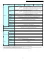
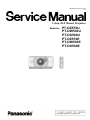
ORDER NO. BSD1011A31CE D10 1-chip DLP Based Projector Model No. PT-DZ570U PT-DW530U PT-DX500U PT-DZ570E PT-DW530E PT-DX500E PT-DZ570U / PT-DW530U / PT-DX500U / PT-DZ570E / PT-DW530E / PT-DX500E The service technician is required to read and follow the “Safety Precautions” and “Important Safety Notice” in this service manual. WARNING This service information is designed for experienced repair technicians only and is not designed for use by the general public. It dose not contain warnings or cautions to advise non-technical individuals of potential dangers in attempting to service a product. Products powered by electricity should be serviced or repaired only by experienced professional technicians. Any attempt to service or repair the product or products dealt with in this service information by anyone else could result in serious injury or death. WARNING : Use UV Radiation eye and skin protection during servicing. CAUTION Lithium Battery Risk of explosion if battery is replaced by an incorrect type, Replace only with the same of equivalent type recommended by the manufacturer. Dispose of used batteries according to the manufacturer’s instructions. Precaution If using of this projector at high altitudes (above 1,400m), set HIGHT ALTITUDE MODE to “ON”. (Refer to “PROJECTOR SETUP menu” in Operating Instructions.) Failure to observe this may cause malfunctions. Never use this projector at an altitude of 2,700m or higher. Using this projector at high altitude, consult your dealer or Authorized Service Center about preparations. About lead free solder (PbF) This projector is using the P.C.Board which applies lead free solder. Use lead free solder in servicing from the standpoint of antipollution for the global environment. Notes: ・Lead free solder: Sn-Ag-Cu (tin, silver and copper) has a higher melting point (approx. 217°C) than standard solder. Typically the melting point ・is 30~40 °C higher. When servicing, use a high temperature soldering iron with temperature limitation function and set it to 370 ± 10 °C. ・Be precautious about lead free solder. Sn-Ag-Cu (tin, silver and copper) will tend to splash when heated too high (approx. 600°C or higher). ・Use lead free solder for the P.C.Board (specified on it as “PbF”) which uses lead free solder. (When you unavoidably use lead solder, use lead ・solder after removing lead free solder. Or be sure to heat the lead free solder until it melts completely, before applying lead solder.) ・After soldering to double layered P.C.Boards, check the component side for excess solder which may flow onto the opposite side. About the identification of the lead free solder P.C.Board. For the P.C.Board which applies lead free solder, the symbol as shown in the figure below is printed or stamped on the surface or the back of P.C.Board. For US IMPORTANT SAFETY NOTICE There are special parts used in Panasonic LCD Projectors which are important for safety. These parts are shaded on the schematic diagram. It is essential that these critical parts should be replaced with manufacturer’s specified parts to prevent shock, fire, or other hazards. Do not modify the original design without permission of PANASONIC BROADCAST & TELEVISION SYSTEMS COMPANY. WARNING: This equipment has been tested and found to comply with the limits for a Class B digital device, pursuant to Part 15 of the FCC Rules. These limits are designed to provide reasonable protection against harmful interference in a residential installation. This equipment generates, uses and can radiate radio frequency energy and, if not installed and used in accordance with the instructions, may cause harmful interference to radio communications. However, there is no guarantee that interference will not occur in a particular installation. If this equipment dose cause harmful interference to radio or television reception, which can be determined by turning the equipment off and on, The user is encouraged to try to correct the interference by one or more of the following measures. - Reorient or relocate the receiving antenna. - Increase the separation between the equipment and receiver. - Connect the equipment into an outlet on a circuit different from that to which the receiver is connected. - Consult the dealer or an experienced radio/TV technician for help. CAUTION : Any unauthorized changes or modifications to this equipment will void the users authority to operate. 2 PT-DZ570U / PT-DW530U / PT-DX500U / PT-DZ570E / PT-DW530E / PT-DX500E CONTENTS ■ Cover Page 1. Safety Precautions 2. Specifications ■ SECTION 1 <Service Information> 1. The name of each part 2. Menu Navigation 3. Service Mode 4. External Controls 5. Cautions for Service 6. Troubleshooting ■ SECTION 2 <Disassembly Procedures> 1. Parts Location 2. Disassembly Instructions ■ SECTION 3 <Adjustment> 1. Adjustment Procedure 2. Software update procedure ■ SECTION 4 <Schematic Diagrams> 1. Block Diagram 2. Interconnection Block Diagram 3. Schematic Diagram 4. Circuit Boards Diagrams ■ SECTION 5 <Exploded Views & Replacement Parts List> 1. Exploded Views 2. Replacement Parts List ■SECTION 6 <Control Commands List> 3 PT-DZ570U / PT-DW530U / PT-DX500U / PT-DZ570E / PT-DW530E / PT-DX500E 1. Safety Precautions 1.1. General Guidelines · For continued safety, no modification of any circuit must be attempted. · Unplug the power cord from the power outlet before disassembling this projector. · Use correctly the supplied power cord and must ground it. · It is advisable to use an isolation transformer in the AC power line before the service. Fig. 2 · Be careful not to touch the rotation part (cooling fan, etc.) of this projector when you service with the upper case removed and the power supply turned ON. 2. Assemble the circuit as shown in Fig. 2. Plug the power cord in a power outlet. 3. Connect M1 to T1 according to Fig. 2 and measure the voltage. · Observe the original lead dress during the service. If a short circuit is found, replace all the parts overheated or damaged by the short circuit. 4. Change the connection of M1 from T1 to T2 and measure the voltage again. · After the service, all the protective devices such as insulation barriers, insulation papers, shields, and isolation R-C combinations must be properly installed. 5. The voltmeter must read 0.375 V or lower in both of steps 3 and 4. This means that the current must be 0.75mA or less. · After the service, check the leakage current to prevent the customer from getting an electric shock. 6. If the reading is out of the above standard, the projector must be repaired and rechecked before returning to the customer because of a possibility of an electric shock. 1.2. Leakage Current Check 1. Prepare the measuring circuit as shown in Fig.1. 1.3. UV Precaution and UHM Lamp Precautions Be sure to use a voltmeter having the performance described in Table 1. · Be sure to unplug the power cord from the power outlet when replacing the lamp. · Because the lamp reaches a very high temperature during its operation, wait until it cools completely when replacing the Lamp Unit. · The lamp emits small amounts of UV-radiation, avoid direct-eye contact with the light. · The lamp unit has high internal pressure. If improperly handled, explosion might result. · Because the high pressure lamp involves a risk of failure, never touch the lamp wire lead during the service. Fig. 1 Table 1 4 PT-DZ570U / PT-DW530U / PT-DX500U / PT-DZ570E / PT-DW530E / PT-DX500E 2. Specifications Model No. PT-DZ570U PT-DZ570E PT-DW530U PT-DW530E Power supply AC100 V - 240 V PT-DX500U PT-DX500E 50Hz/60Hz 415 W Power consumption When [STANDBY MODE] is [ECO] : Approx. 0.4 W When [STANDBY MODE] is [NORMAL] : Approx. 15 W Amps 5.0 A – 1.9 A Panel size DLP chip 0.67 inch (aspect ratio 16 : 10) Display system Number of pixels 0.65 inch (aspect ratio 16 : 10) 0.70 inch (aspect ratio 4 : 3) 1 unit DLP chip, DLP type 2 304 000 pixels (1 920 × 1 200 dots) 1 024 000 pixels (1 280 × 800 dots) 786 432 pixels (1 024 × 768 dots) Manual zoom (2x) / Manual focus F 2.0 - 3.4, f 21.5 mm - 43.0 mm Lens Projection lamp 1 bulbs × 300 W (Max 310 W) Optical output *1 UHM lamp 4 000 lm (ANSI) 4 500 lm (ANSI) H : 15 kHz - 100 kHz, V : 24 Hz - 120 Hz PIAS (Panasonic Intelligent Auto Scanning) system For RGB signal Dot clock frequency Less than 162 MHz Applicable scanning frequency*2 For YPBPR signal [480i] [480p] [720/50p] [1 035/60i] [1 080/60i] [1 080/25p] [1 080/30p] [1 080/50p] H: 15.73 kHz, V: 59.94 Hz H: 31.5 kHz, V: 59.94 Hz H: 37.5 kHz, V: 50 Hz H: 33.75 kHz, V: 60 Hz H: 33.75 kHz, V: 60 Hz H: 28.13 kHz, V: 25 Hz H: 33.75 kHz, V: 30 Hz H: 56.25 kHz, V: 50 Hz [576i] [576p] [720/60p] [1 080/50i] [1 080/24p] [1 080/24sF] [1 080/60p] H: 15.63 kHz, V: 50 Hz H: 31.25 kHz, V: 50 Hz H: 45 kHz, V: 60 Hz H: 28.13 kHz, V: 50 Hz H: 27 kHz, V: 24 Hz H: 27 kHz, V: 48 Hz H: 67.5 kHz, V: 60 Hz HD/SYNC, VD terminals are not compliant with 3 value composite SYNC. For video signal H : 15.75 kHz/15.63 kHz, V : 50 Hz/60 Hz (S-video included) For DVI-D/HDMI signal Color system 480p, 576p, 720/60p, 720/50p, 1 080/60p, 1 080/50p, 1 080/60i, 1 080/50i, 1 080/24sF, 1 080/30p, 1 080/25p, 1 080/24p Displayable resolution : VGA - WUXGA (non-interlace) Dot clock frequency : 25 MHz - 162 MHz 7 standards (NTSC/NTSC4.43/PAL/PAL-N/PAL-M/SECAM/PAL60) Screen size Screen aspect ratio Projection scheme 40 inch - 300 inch 16 : 10 16 : 9 4:3 Menu-selectable from front/rear/ceiling mount, and floor mounting Contrast ratio 2 000 : 1 Power cord length 3.0 m Cabinet Molded plastic 5 PT-DZ570U / PT-DW530U / PT-DX500U / PT-DZ570E / PT-DW530E / PT-DX500E Model No. PT-DZ570U PT-DZ570E 1 set, BNC × 5 [RGB signal] RGB1 IN [YPBPR signal] RGB2 IN PT-DW530U PT-DW530E 0.7 V [p-p] 75 Ω (G-SYNC : 1.0 [p-p] 75 Ω) HD/SYNC TTL high impedance, automatic positive/negative polarity compatible VD TTL high impedance, automatic positive/negative polarity compatible Y : 1.0 V [p-p] Synchronization signal included, PBPR : 0.7 V [p-p] 75 Ω 1 set of high density, D-sub 15-pin (female) [RGB signal] 0.7 V [p-p] 75 Ω (G-SYNC : 1.0 [p-p] 75 Ω) HD/SYNC TTL high impedance, automatic positive/negative polarity compatible VD TTL high impedance, automatic positive/negative polarity compatible [YPBPR signal] Y : 1.0 V [p-p] Synchronization signal included, PBPR : 0.7 V [p-p] 75 Ω VIDEO IN Terminals S-VIDEO IN PT-DX500U PT-DX500E 1 set, BNC, 1.0 V [p-p] 75 Ω 1 set, Mini DIN 4-pin, Y: 1.0 V [p-p], C: 0.286 V [p-p] 75 Ω, compatible with S1 signal DVI-D IN 1 set, DVI-D 24-pin (Single link), DVI 1.0 compatible, HDCP compatible HDMI IN 1 set, HDMI 19-pin (HDCP/Deep color compatible) SERIAL IN/OUT REMOTE 1 IN/OUT 1 set, D-sub 9-pin, RS-232C compatible, computer control use 1 set, M3 pin jack, wired remote control use, multiple connection use REMOTE 2 IN LAN 1 set, D-sub 9-pin, external control use 1 set, RJ-45, network connection use, PJ-Link compatible, 10 Base-T/100Base-TX Width : 530 mm (20 7/8"), Length : 200 mm (7 7/8"), Height : 548.5 mm (21 19/32") (540 mm (21 1/4") : not including surface projection parts) Dimensions Weight Approx. 24.0 kg (52.9 lbs.) *3 Operating environment Temperature *4 : 0 °C to 45 °C / Humidity : 10 % to 80 % (no condensation) Power supply Operating range DC 3 V (AA/R6 battery × 2) Approx. 30 m (98'5") (when operated directly in front of signal receptor) Remote control Weight Dimensions Ceiling bracket Replacement Lamp Unit Options 134 g (including batteries) Width : 51 mm (2"), Length : 176 mm (6 15/16"), Height : 28 mm (1 3/32") For high ceiling : ET-PKD310H / For low ceiling : ET-PKD310S Ceiling Mount Attachment : ET-PAD310 ET-LAD310 (1 bulb), ET-LAD310W (2 bulbs) Replacement filter unit ET-ACF310 Smoke Cut Filter ET-SFD310 Frame ET-PFD310 *1: Measurement, measuring conditions and method of notation all comply with ISO21118 international standards. *2: For details of video signals that can be projected using this projector, refer to “List of compatible signals” *3: This is the average value. It may differ depending on each product. *4: When using this projector at high elevations 1 400 - 2 700 m (4 593 - 8 858 ft) sea level, temperature will be 5 °C lower than this higher limit. The part numbers of accessories and separately sold components are subject to change without notice. 6 PT-DZ570U / PT-DW530U / PT-DX500U / PT-DZ570E / PT-DW530E / PT-DX500E 7