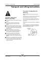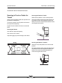
1
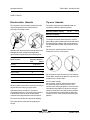
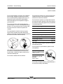
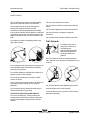
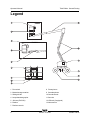
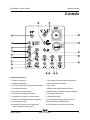
Operator’s Manual
with Maintenance Information
Bi-Energy
IC
Power Power
Third Edition
Second Printing
Part No. 110015
Operator's Manual
Third Edition · Second Printing
Important
Read, understand and obey these safety rules and
operating instructions before operating this machine.
Only trained and authorized personnel shall be
permitted to operate this machine. This manual should
be considered a permanent part of your machine and
should remain with the machine at all times. If you
have any questions, call Genie Industries.
Contents
Page
Safety Rules .............................................................. 1
Legend ....................................................................... 8
Controls ..................................................................... 9
Pre-operation Inspection ........................................... 12
Maintenance ............................................................. 14
Function Tests .......................................................... 18
Workplace Inspection ................................................ 24
Operating Instructions ............................................... 25
Transport and Lifting Instructions .............................. 31
Decals ...................................................................... 34
Specifications ........................................................... 38
Copyright © 1998 by Genie Industries
Contact us:
First Edition:
Internet: http://www.genielift.com
E-mail: [email protected]
Seventh Printing, May 2002
Second Edition: Second Printing, August 2004
Third Edition:
Second Printing, October 2005
"Genie" and "Z" are registered trademarks of
Genie Industries in the U.S.A. and many other
countries.
These machines comply with
ANSI/SIA 92.5-1992.
Printed on recycled paper
Printed in U.S.A.
Z-45/25 • Z-45/25J
Part No. 110015
Third Edition · Second Printing
Operator's Manual
Safety Rules
Danger
Failure to obey the instructions and
safety rules in this manual will result
in death or serious injury.
Do Not Operate Unless:
You learn and practice the principles of safe
machine operation contained in this operator's
manual.
1 Avoid hazardous situations.
Know and understand the safety rules before
going on to the next section.
2 Always perform a pre-operation inspection.
3 Always perform function tests prior to use.
4 Inspect the workplace.
5 Only use the machine as it was intended.
You read, understand and obey the
manufacturer's instructions and safety rules—
safety and operator's manuals and machine
decals.
You read, understand and obey employer's
safety rules and worksite regulations.
You read, understand and obey all applicable
governmental regulations.
You are properly trained to safely operate the
machine.
Part No. 110015
Z-45/25 • Z-45/25J
1
Operator's Manual
Third Edition · Second Printing
SAFETY RULES
Electrocution Hazards
Tip-over Hazards
This machine is not electrically insulated and will
not provide protection from contact with or
proximity to electrical current.
Occupants, equipment and materials shall not
exceed the maximum platform capacity.
Maximum platform capacity
500 lbs
227 kg
Maximum occupants
2
The weight of options and accessories, such as
pipe cradles, panel cradles and welders, will reduce
the rated platform capacity and must be factored
into the total platform load. See the decals on the
options.
Maintain safe distances from electrical power lines
and apparatus in accordance with applicable
governmental regulations and the following chart.
Voltage
Phase to Phase
Do not raise or extend the boom unless the
machine is on a firm, level surface.
Minimum Safe
Approach Distance
Feet
Meters
0 to 300V
Avoid Contact
300V to 50KV
10
3.1
50KV to 200KV
15
4.6
200KV to 350KV
20
6.1
350KV to 500KV
25
7.6
500KV to 750KV
35
10.7
750KV to 1000KV
45
13.7
Allow for platform movement, electrical line sway or
sag and beware of strong or gusty winds.
Keep away from the machine if it contacts
energized power lines. Personnel on the ground or
in the platform must not touch or operate the
machine until energized power lines are shut off.
Do not depend on the tilt alarm as a level indicator.
The tilt alarm sounds in the platform only when the
machine is on a severe slope.
If the tilt alarm sounds:
Do not extend, rotate or raise the boom above
horizontal. Move the machine to a firm, level
surface before raising the platform. If the tilt alarm
sounds when the platform is raised, use extreme
caution to retract the boom and lower the platform.
Do not rotate the boom while lowering. Move the
machine to a firm, level surface before raising the
platform.
Do not use the machine as a ground for welding.
Do not operate the machine during lightning or
storms.
2
Z-45/25 • Z-45/25J
Part No. 110015
Third Edition · Second Printing
Operator's Manual
SAFETY RULES
Do not use the platform controls to free a platform
that is caught, snagged or otherwise prevented
from normal motion by an adjacent structure. All
personnel must be removed from the platform
before attempting to free the platform using the
ground controls.
Do not raise the boom when wind speeds may
exceed 28 mph / 12.5 m/s. If wind speeds exceed
28 mph / 12.5 m/s when the boom is raised, lower
the boom and do not continue to operate the
machine.
Do not operate the machine in strong or gusty
winds. Do not increase the surface area of the
platform or the load. Increasing the area exposed to
the wind will decrease machine stability.
Do not drive the machine on or near uneven terrain,
unstable surfaces or other hazardous conditions
with the boom raised or extended.
Do not drive the machine on a slope that exceeds
the maximum uphill, downhill or side slope rating of
the machine. Slope rating applies only to machines
in the stowed position.
Maximum slope rating, stowed position, 2WD
Counterweight uphill
30% (17°)
Counterweight downhill
25% (14°)
Side slope
25% (14°)
Maximum slope rating, stowed position, 4WD
Counterweight uphill
45% (24°)
Counterweight downhill
25% (14°)
Side slope
25% (14°)
Note: Slope rating is subject to ground conditions
and adequate traction.
Do not push off or pull toward any object outside
of the platform.
Use extreme care and slow speeds while driving
the machine in stowed position across uneven
terrain, debris, unstable or slippery surfaces and
near holes and drop-offs.
Do not alter or disable the limit switches.
Maximum allowable
side force - ANSI and CSA
150 lbs / 667 N
Maximum allowable
manual force - CE and
Australia
90 lbs / 400 N
Do not alter or disable machine components that in
any way affect safety and stability.
Part No. 110015
Z-45/25 • Z-45/25J
3
Operator's Manual
Third Edition · Second Printing
SAFETY RULES
Do not replace items critical to machine stability
with items of different weight or specification.
Do not modify or alter an aerial work platform
without prior written permission from the
manufacturer. Mounting attachments for holding
tools or other materials onto the platform, toeboards
or guard rail system can increase the weight in the
platform and the surface area of the platform or the
load.
Do not place or attach overhanging loads to any
part of this machine.
Do not use the machine as a crane.
Do not push the machine or other objects with the
boom.
Do not contact adjacent structures with the boom.
Do not tie the boom or platform to adjacent
structures.
Do not place loads outside the platform perimeter.
Fall Hazards
Occupants must wear a
safety belt or harness in
accordance with
governmental regulations.
Attach the lanyard to the
anchor provided in the
platform.
Do not sit, stand or climb on the platform guard
rails. Maintain a firm footing on the platform floor at
all times.
Do not transport tools and materials unless they are
evenly distributed and can be safely handled by
person(s) in the platform.
Do not place ladders or scaffolds in the platform or
against any part of this machine.
Do not use the machine on a moving or mobile
surface or vehicle.
Be sure all tires are in good condition, air-filled tires
are properly inflated and lug nuts are properly
tightened.
Do not replace factory-installed tires with tires of
different specification or ply rating.
Z-45/25 and Z-45/25J Narrow Base Models:
Do not use air-filled tires. These machines are
equipped with foam-filled tires. Wheel weight and
proper counterweight configuration are critical to
stability.
4
Do not climb down from the platform when raised.
Keep the platform floor clear of debris.
Lower the platform entry mid-rail or close the entry
gate before operating.
Z-45/25 • Z-45/25J
Part No. 110015
Third Edition · Second Printing
Operator's Manual
SAFETY RULES
Collision Hazards
Be aware of limited sight
distance and blind spots
when driving or operating.
Be aware of the boom position when rotating the
turntable.
Check the work area for overhead obstructions or
other possible hazards.
Operators must comply with employer, job site and
governmental rules regarding the use of personal
protective equipment.
Observe and use the color-coded direction arrows
on the platform controls and drive chassis for drive
and steer functions.
Do not operate a boom in the path of any crane
unless the controls of the crane have been locked
out and/or precautions have been taken to prevent
any potential collision.
No stunt driving or horseplay while operating a
machine.
Component Damage Hazards
Do not use any battery or charger greater than 12V
to jump-start the engine.
Do not use the machine as a ground for welding.
Be aware of crushing hazards when grasping the
platform guard rail.
Explosion and Fire Hazards
Do not lower the boom unless the area below is
clear of personnel and obstructions.
Do not start the engine if you smell or detect liquid
petroleum gas (LPG), gasoline, diesel fuel or other
explosive substances.
Do not refuel the machine with the engine running.
Refuel the machine and charge the battery only in
an open, well-ventilated area away from sparks,
flames and lighted tobacco.
Do not operate the machine in hazardous locations
or locations where potentially flammable or
explosive gases or particles may be present.
Limit travel speed according to the condition of the
ground surface, congestion, slope, location of
personnel, and any other factors which may cause
collision.
Part No. 110015
Do not spray ether into engines equipped with glow
plugs.
Z-45/25 • Z-45/25J
5
Operator's Manual
Third Edition · Second Printing
Damaged Machine Hazards
Battery Safety
Do not use a damaged or malfunctioning machine.
Conduct a thorough pre-operation inspection of the
machine and test all functions before each work
shift. Immediately tag and remove from service a
damaged or malfunctioning machine.
Be sure all maintenance has been performed as
specified in this manual and the Genie Z-45/25 &
Genie Z-45/25J Service Manual.
Be sure all decals are in place and legible.
Be sure the operator’s, safety and responsibilities
manuals are complete, legible and in the storage
container located on the platform.
Burn Hazards
Batteries contain acid. Always wear protective
clothing and eye wear when working with batteries.
Avoid spilling or contacting battery acid. Neutralize
battery acid spills with baking soda and water.
Explosion Hazard
Keep sparks, flames and lighted tobacco away
from batteries. Batteries emit explosive gas.
Electrocution Hazard
Avoid contact with electrical terminals.
Bodily Injury Hazard
Do not operate the machine with a hydraulic oil or
air leak. An air leak or hydraulic leak can penetrate
and/or burn skin.
Always operate the machine in a well-ventilated
area to avoid carbon monoxide poisoning.
Improper contact with components under any cover
will cause serious injury. Only trained maintenance
personnel should access compartments. Access
by the operator is only advised when performing a
pre-operation inspection. All compartments must
remain closed and secured during operation.
6
Z-45/25 • Z-45/25J
Part No. 110015
Third Edition · Second Printing
Operator's Manual
Decal Legend
Genie product decals use symbols, color coding
and signal words to identify the following:
Safety alert symbol—used to alert
personnel to potential personal
injury hazards. Obey all safety
messages that follow this symbol
to avoid possible injury or death.
Red—used to indicate the
presence of an imminently
hazardous situation which, if not
avoided, will result in death or
serious injury.
Orange—used to indicate the
presence of a potentially
hazardous situation which, if not
avoided, could result in death or
serious injury.
Yellow with safety alert symbol—
used to indicate the presence of a
potentially hazardous situation
which, if not avoided, may cause
minor or moderate injury.
Yellow without safety alert
symbol—used to indicate the
presence of a potentially
hazardous situation which, if not
avoided, may result in property
damage.
Green—used to indicate operation
or maintenance information.
Part No. 110015
Z-45/25 • Z-45/25J
7
Operator's Manual
Third Edition · Second Printing
Legend
Z-45/25
Z-45/25J
1 Foot switch
8 Primary boom
2 Manual storage container
9 Secondary boom
3 Sliding mid-rail
10 Ground controls
4 Lanyard anchorage point
11 Steer tire
5 Jib boom (Z-45/25J)
12 LPG tank (if equipped)
6 Platform
13 Non-steer tire
7 Platform controls
8
Z-45/25 • Z-45/25J
Part No. 110015
Third Edition · Second Printing
Operator's Manual
Controls
Ground Control Panel
1 Platform level switch
11 Key switch for platform/off/ground selection
2 Platform rotate switch
12 Red Emergency Stop button
3 Z-45/25J models only: Jib boom up/down switch
13 Hour meter
4 Turntable rotate switch
14 Diesel models: Water temperature light
5 Primary boom up/down switch
15 Diesel models: Glow plug switch (if equipped)
6 Primary boom extend/retract switch
16 Function enable switch
7 Gasoline/LPG models: Fuel select switch
17 Engine start switch
8 Platform overload indicator light (if equipped)
18 15A breaker for engine electrical circuits
9 Auxiliary power switch
19 Secondary boom up/down switch
10 Gasoline/LPG models: Check engine light
Diesel models: Oil pressure light
20 15A breaker for control electrical circuits
Part No. 110015
Z-45/25 • Z-45/25J
9
Operator's Manual
Third Edition · Second Printing
CONTROLS
1
2
3
4
19
20
5
18
17
Platform Control Panel
6 Drive speed select switch
1 Horn button
7 Diesel models: Glow plug switch
2 Platform level switch
8 Engine start switch
3 Platform rotate switch
9 Engine idle (rpm) select switch
4 Z-45/25J models only: Jib boom up/down switch
10 Gasoline/LPG models: Gasoline/LPG
select switch
5 Auxiliary power switch
10
Z-45/25 • Z-45/25J
Part No. 110015
6
Third Edition · Second Printing
Operator's Manual
CONTROLS
7
16
8
15
9
14
10
13
11
12
11 Red Emergency Stop button
16 Drive enable switch
12 Dual axis proportional control handle for drive
and steer functions
OR Proportional control handle for drive function
and thumb rocker for steer function
17 Proportional control handle for secondary boom
up/down function
13 Platform overload indicator light (if equipped)
14 Machine not level indicator light (if equipped)
15 Drive enable indicator light
Part No. 110015
18 Primary boom extend/retract switch
19 used for optional equipment
20 Dual axis proportional control handle for primary
boom up/down and turntable rotate
left/right functions
Z-45/25 • Z-45/25J
11
Operator's Manual
Third Edition · Second Printing
Pre-operation Inspection
Fundamentals
It is the responsibility of the operator to perform a
pre-operation inspection and routine maintenance.
Do Not Operate Unless:
You learn and practice the principles of safe
machine operation contained in this operator's
manual.
1 Avoid hazardous situations.
2 Always perform a pre-operation
inspection.
Know and understand the pre-operation
inspection before going on to the next
section.
3 Always perform function tests prior to use.
4 Inspect the workplace.
5 Only use the machine as it was intended.
The pre-operation inspection is a visual inspection
performed by the operator prior to each work shift.
The inspection is designed to discover if anything
is apparently wrong with a machine before the
operator performs the function tests.
The pre-operation inspection also serves to
determine if routine maintenance procedures are
required. Only routine maintenance items specified
in this manual may be performed by the operator.
Refer to the list on the next page and check each
of the items.
If damage or any unauthorized variation from
factory delivered condition is discovered, the
machine must be tagged and removed from
service.
Repairs to the machine may only be made by a
qualified service technician, according to the
manufacturer's specifications. After repairs are
completed, the operator must perform a
pre-operation inspection again before going on to
the function tests.
Scheduled maintenance inspections shall be
performed by qualified service technicians,
according to the manufacturer's specifications and
the requirements listed in the responsibilities
manual.
12
Z-45/25 • Z-45/25J
Part No. 110015
Third Edition · Second Printing
Operator's Manual
PRE-OPERATION INSPECTION
Pre-operation Inspection
o Be sure that the operator’s, safety and
responsibilities manuals are complete, legible
and in the storage container located in the
platform.
o Be sure that all decals are legible and in place.
See Decals section.
o Check for engine oil leaks and proper oil level.
Add oil if needed. See Maintenance section.
o Check for hydraulic oil leaks and proper oil level.
Add oil if needed. See Maintenance section.
o Check for engine coolant leaks and proper level
of coolant. Add coolant if needed. See
Maintenance section.
o Check for battery fluid leaks and proper fluid
level. Add distilled water if needed. See
Maintenance section.
o Z-45/25 RT and Z-45/25J RT models: Check for
proper tire pressure. Add air if needed. See
Maintenance section.
o Engine and related components
o Limit switches and horn
o Alarms and beacons (if equipped)
o Nuts, bolts and other fasteners
o Platform entry mid-rail or gate
Check entire machine for:
o Cracks in welds or structural components
o Dents or damage to machine
o Be sure that all structural and other critical
components are present and all associated
fasteners and pins are in place and properly
tightened.
o After you complete your inspection, be sure that
all compartment covers are in place and
latched.
Check the following components or areas for
damage, improperly installed or missing parts and
unauthorized modifications:
o Electrical components, wiring and
electrical cables
o Hydraulic hoses, fittings, cylinders and
manifolds
o Fuel and hydraulic tanks
o Drive and turntable motors and drive hubs
o Boom wear pads
o Tires and wheels
Part No. 110015
Z-45/25 • Z-45/25J
13
Operator's Manual
Third Edition · Second Printing
Maintenance
Check the Engine Oil Level
Maintaining the proper engine oil level is essential
to good engine performance and service life.
Operating the machine with an improper oil level
can damage engine components.
Observe and Obey:
Only routine maintenance items specified in this
manual shall be performed by the operator.
Scheduled maintenance inspections shall be
completed by qualified service technicians,
according to the manufacturer's specifications
and the requirements specified in the
responsibilities manual.
Check the oil level with the
engine off.
1 Check the oil dipstick. Add oil as needed.
Perkins 404C-22 Engine
Oil type
15W-40
Oil type - cold conditions
5W-40
Ford LRG-425 EFI Engine (EPA Compliant)
Oil type
Maintenance Symbols Legend
Oil type - cold conditions
The following symbols have been
used in this manual to help
communicate the intent of the
instructions. When one or more of
the symbols appear at the
beginning of a maintenance
procedure, it conveys the meaning
below.
10W-40
5W-30
Deutz F3L 2011 Engine
Oil type
Oil type - cold conditions
15W-40
5W-30
Indicates that tools will be required to
perform this procedure.
Indicates that new parts will be required to
perform this procedure.
Indicates that a cold engine is required
before performing this procedure.
14
Z-45/25 • Z-45/25J
Part No. 110015
Third Edition · Second Printing
Operator's Manual
MAINTENANCE
Check the Hydraulic Oil Level
Maintaining the hydraulic oil at the proper level is
essential to machine operation. Improper hydraulic
oil levels can damage hydraulic components. Daily
checks allow the inspector to identify changes in oil
level that might indicate the presence of hydraulic
system problems.
1 Be sure that the boom is in the stowed position,
then visually inspect the sight gauge located on
the side of the hydraulic oil tank.
Check the Engine Coolant Level
- Ford and Perkins Models
Maintaining the engine coolant at the proper level is
essential to engine service life. Improper coolant
level will affect the engine's cooling capability and
damage engine components. Daily checks will
allow the inspector to identify changes in coolant
level that might indicate cooling system problems.
Burn hazard. Beware of hot engine
parts and coolant. Contact with hot
engine parts and/or coolant may
cause severe burns.
Result: The hydraulic oil level should be within
the top 2 inches / 5 cm of the sight gauge.
2 Add oil as needed.
1 Check the fluid level in the coolant recovery
tank. Add fluid as needed.
Hydraulic oil specifications
Hydraulic oil type
Chevron Rykon
Premium MV equivalent
Result: The fluid level should be at the
FULL mark.
Do not remove the radiator cap.
Part No. 110015
Z-45/25 • Z-45/25J
15
Operator's Manual
Third Edition · Second Printing
MAINTENANCE
Check the Batteries
Check the Tire Pressure
Proper battery condition is essential to good engine
performance and operational safety. Improper fluid
levels or damaged cables and connections can
result in engine component damage and hazardous
conditions.
Tip-over hazard. An over-inflated
tire can explode which may
compromise machine stability and
cause the machine to tip over.
Tip-over hazard. The use of
temporary flat tire repair products
may lead to tire failure which could
compromise machine stability and
cause the machine to tip over.
Electrocution hazard. Contact with
hot or live circuits may result in
death or serious injury. Remove all
rings, watches and other jewelry.
Bodily injury hazard. Batteries
contain acid. Avoid spilling or
contacting battery acid. Neutralize
battery acid spills with baking soda
and water.
Bodily injury hazard. An overinflated tire can explode and may
cause death or serious injury.
This procedure does not need to
be performed on machines
equipped with foam-filled tires.
1 Put on protective clothing and eye wear.
2 Be sure that the battery cable connections are
tight and free of corrosion.
1 Check each tire with an air pressure gauge and
add air as needed.
3 Be sure that the battery hold-down bracket is
secure.
Tire specifications
4 Remove the battery vent caps.
Narrow base models
Industrial tire
5 Check the battery acid level. If needed,
replenish with distilled water to the bottom of
the battery fill tube. Do not overfill.
6 Install the vent caps.
Adding terminal protectors and a
corrosion preventative sealant will
help eliminate corrosion on the
battery terminals and cables.
16
2WD Models
Foam-filled
Only
Standard base models
Industrial tire
Tire size: 9-14.5 LT
Standard base models
Rough terrain tire
Tire size: 355/55D625 14 ply
Z-45/25 • Z-45/25J
4WD Models
100 psi /
6.9 bar
50 psi /
3.5 bar
50 psi /
3.5 bar
Part No. 110015
Third Edition · Second Printing
Operator's Manual
MAINTENANCE
Scheduled Maintenance
Maintenance performed quarterly, annually and
every two years must be completed by a person
trained and qualified to perform maintenance on this
machine according to the procedures found in the
service manual for this machine.
Machines that have been out of service for more
than three months must receive the quarterly
inspection before they are put back into service.
Part No. 110015
Z-45/25 • Z-45/25J
17
Operator's Manual
Third Edition · Second Printing
Function Tests
Fundamentals
The function tests are designed to discover any
malfunctions before the machine is put into
service. The operator must follow the step-by-step
instructions to test all machine functions.
Do Not Operate Unless:
You learn and practice the principles of safe
machine operation contained in this operator's
manual.
1 Avoid hazardous situations.
A malfunctioning machine must never be used. If
malfunctions are discovered, the machine must be
tagged and removed from service. Repairs to the
machine may only be made by a qualified service
technician, according to the manufacturer's
specifications.
After repairs are completed, the operator must
perform a pre-operation inspection and function
tests again before putting the machine into service.
2 Always perform a pre-operation
inspection.
3 Always perform function tests prior to
use.
Know and understand the function tests
before going on to the next section.
4 Inspect the workplace.
5 Only use the machine as it was intended.
18
Z-45/25 • Z-45/25J
Part No. 110015
Third Edition · Second Printing
Operator's Manual
FUNCTION TESTS
1 Select a test area that is firm, level and free of
obstruction.
At the Ground Controls
2 Turn the key switch to ground control.
3 Pull out the red Emergency Stop button to
the on position.
Result: The beacon (if equipped) should flash.
4 Start the engine. See Operating Instructions
section.
Test Emergency Stop
5 Push in the red Emergency Stop button to the
off position.
Result: The engine will shut off after 2 to 3
seconds.
6 Pull out the red Emergency Stop button to
the on position and restart the engine.
Test the Machine Functions
Test the Tilt Sensor
9 Turn the key switch to
platform control. Pull out
the platform red Emergency
Stop button to the on
position.
10 Open the engine side
turntable cover and locate
the tilt sensor to the right of
the hydraulic pump.
11 Press down one side of the tilt sensor.
Result: The alarm, located in the platform,
should sound.
Test Auxiliary Controls
12 Turn the key switch to ground control and shut
the engine off.
13 Pull out the red Emergency
Stop button to the on position.
14 Simultaneously hold the
auxiliary power switch on and
activate each boom function
toggle switch.
7 Do not hold the function enable
switch to either side. Attempt to
activate each boom and platform
function toggle switch.
Result: All boom and platform functions should
not operate.
Note: To conserve battery power, test each
function through a partial cycle.
Result: All boom functions should operate.
8 Hold the function enable switch to either side
and activate each boom and platform function
toggle switch.
Result: All boom and platform functions should
operate through a full cycle. The descent alarm
(if equipped) should sound while the boom is
lowering.
Part No. 110015
Z-45/25 • Z-45/25J
19
Operator's Manual
Third Edition · Second Printing
FUNCTION TESTS
At the Platform Controls
Test Machine Functions
Test Emergency Stop
24 Press down the foot switch.
15 Turn the key switch to platform control and
restart the engine.
25 Activate each machine function control handle
or toggle switch.
16 Push in the platform red Emergency Stop
button to the off position.
Result: All boom/platform functions should
operate through a full cycle.
Result: The engine will shut off after 2 or 3
seconds.
17 Pull out the red Emergency Stop button and
restart the engine.
Test the Horn
18 Push the horn button.
Result: The horn should sound.
Test the Steering
26 Press down the foot switch.
27 Press the thumb rocker switch on top of the
drive control handle in the direction indicated by
the blue triangle on the control panel OR slowly
move the control handle in the direction
indicated by the blue triangle.
Result: The steer wheels should turn in the
direction that the blue triangles point on the
drive chassis.
Test the Foot Switch
19 Push in the platform red Emergency Stop button
to the off position.
20 Pull out the red Emergency Stop button to
the on position but do not start the engine.
21 Press down the foot switch and attempt to start
the engine by moving the start toggle switch to
either side.
Result: The engine should not start.
28 Press the thumb rocker switch on top of the
drive control handle in the direction indicated by
the yellow triangle on the control panel OR
slowly move the control handle in the direction
indicated by the yellow triangle.
Result: The steer wheels should turn in the
direction that the yellow triangles point on the
drive chassis.
22 Do not press down the foot switch and restart
the engine.
Result: The engine should start.
23 Do not press down the foot switch and test each
machine function.
Result: The machine functions should not
operate.
20
Z-45/25 • Z-45/25J
Part No. 110015
Third Edition · Second Printing
Operator's Manual
FUNCTION TESTS
Test Drive and Braking
Test the Drive Enable System
29 Press down the foot switch.
32 Press down the foot switch and lower the boom
to the stowed position.
30 Slowly move the drive control handle in the
direction indicated by the blue arrow on the
control panel until the machine begins to move,
then return the handle to the center position.
Result: The machine should move in the
direction that the blue arrow points on the drive
chassis, then come to an abrupt stop.
31 Slowly move the drive control handle in the
direction indicated by the yellow arrow on the
control panel until the machine begins to move,
then return the handle to the center position.
Result: The machine should move in the
direction that the yellow arrow points on the
drive chassis, then come to an abrupt stop.
Note: The brakes must be able to hold the machine
on any slope it is able to climb.
33 Rotate the turntable until the primary boom
moves past one of the non-steer wheels.
Result: The drive enable
indicator light should come
on and remain on while the
boom is anywhere in the
range shown.
34 Move the drive control handle off center.
Result: The drive function should not operate.
35 Move and hold the drive enable toggle switch to
either side and slowly move the drive control
handle off center.
Result: The drive function should operate.
Note: When the drive enable system is in use, the
machine may drive in the opposite direction that the
drive and steer control handle is moved.
Use the color-coded direction
arrows on the platform
controls and the drive
chassis to identify the
direction of travel.
Blue
Yellow
Part No. 110015
Z-45/25 • Z-45/25J
21
Operator's Manual
Third Edition · Second Printing
FUNCTION TESTS
Test Limited Drive Speed - Standard Base
Models
36 Press down the foot switch.
36 Press down the foot switch.
37 Raise the primary boom approximately
2 feet / 61 cm.
37 Raise the primary boom approximately
2 feet / 61 cm.
38 Slowly move the drive control handle to the full
drive position.
Result: The maximum achievable drive speed
with the primary boom raised should not exceed
1 foot / 30 cm per second.
39 Lower the primary boom to the stowed position.
40 Raise the secondary boom approximately
2 feet / 61 cm.
41 Slowly move the drive control handle to the full
drive position.
Result: The maximum achievable drive speed
with the secondary boom raised should not
exceed 1 foot / 30 cm per second.
42 Lower the secondary boom to the stowed
position.
38 Slowly move the drive control handle to the full
drive position.
Result: The maximum achievable drive speed
with the primary boom raised should not exceed
6 in / 15 cm per second.
39 Lower the primary boom to the stowed position.
40 Raise the secondary boom approximately
2 feet / 61 cm.
41 Slowly move the drive control handle to the full
drive position.
Result: The maximum achievable drive speed
with the secondary boom raised should not
exceed 6 in / 15 cm per second.
42 Lower the secondary boom to the stowed
position.
43 Extend the primary boom approximately
1 foot / 30 cm.
43 Extend the primary boom approximately
1 foot / 30 cm.
44 Slowly move the drive control handle to the full
drive position.
Result: The maximum achievable drive speed
with the primary boom extended should not
exceed 1 foot / 30 cm per second.
45 Retract the boom to the stowed position.
If the drive speed with the primary boom raised, the
secondary boom raised or the primary boom
extended exceeds 1 foot / 30 cm per second,
immediately tag and remove the machine from
service.
22
Test Limited Drive Speed - Narrow Base Models
44 Slowly move the drive control handle to the full
drive position.
Result: The maximum achievable drive speed
with the primary boom extended should not
exceed 6 in / 15 cm per second.
45 Retract the boom to the stowed position.
If the drive speed with the primary boom raised, the
secondary boom raised or the primary boom
extended exceeds 6 in / 15 cm cm per second,
immediately tag and remove the machine from
service.
Z-45/25 • Z-45/25J
Part No. 110015
Third Edition · Second Printing
Operator's Manual
FUNCTION TESTS
Test the Oscillate Axle
(oscillating axle-equipped models)
Test the Lift/Drive Select Function
(if equipped)
46 Start the engine from the platform controls.
54 Press down the foot switch.
47 Drive the right steer tire up onto a 6 inch /
15 cm block or curb.
55 Move the drive control handle off center and
activate a boom function toggle switch.
Result: The three remaining tires should stay in
firm contact with the ground.
48 Drive the left steer tire up onto a 6 inch /
15 cm block or curb.
Result: No boom functions should operate. The
machine will move in the direction indicated on
the control panel.
56 Repair any malfunctions before operating the
machine.
Result: The three remaining tires should stay in
firm contact with the ground.
49 Drive both steer tires up onto a 6 inch /
15 cm block or curb.
Result: The non-steer tires should stay in firm
contact with the ground.
Test Auxiliary Controls
50 Shut the engine off.
51 Pull out the red Emergency Stop button to
the on position.
52 Press down the foot switch.
53 Simultaneously hold the auxiliary power switch
on and activate each function control handle or
toggle switch.
Note: To conserve battery power, test each
function through a partial cycle.
Result: All boom and steer functions should
operate. Drive functions should not operate with
auxiliary power.
Part No. 110015
Z-45/25 • Z-45/25J
23
Operator's Manual
Third Edition · Second Printing
Workplace Inspection
Fundamentals
The workplace inspection helps the operator
determine if the workplace is suitable for safe
machine operation. It should be performed by the
operator prior to moving the machine to the
workplace.
Do Not Operate Unless:
You learn and practice the principles of safe
machine operation contained in this operator's
manual.
1 Avoid hazardous situations.
It is the operator's responsibility to read and
remember the workplace hazards, then watch for
and avoid them while moving, setting up and
operating the machine.
Workplace Inspection
Be aware of and avoid the following hazardous
situations:
2 Always perform a pre-operation
inspection.
3 Always perform function tests prior to use.
4 Inspect the workplace.
Know and understand the workplace
inspection before going on to the next
section.
·
drop-offs or holes
·
bumps, floor obstructions or debris
·
sloped surfaces
·
unstable or slippery surfaces
·
overhead obstructions and high voltage
conductors
·
hazardous locations
·
inadequate surface support to withstand all load
forces imposed by the machine
·
wind and weather conditions
·
the presence of unauthorized personnel
·
other possible unsafe conditions
5 Only use the machine as it was intended.
24
Z-45/25 • Z-45/25J
Part No. 110015
Third Edition · Second Printing
Operator's Manual
Operating Instructions
Fundamentals
The Operating Instructions section provides
instructions for each aspect of machine operation.
It is the operator's responsibility to follow all the
safety rules and instructions in the operator's,
safety and responsibilities manuals.
Using the machine for anything other than lifting
personnel, along with their tools and materials, to
an aerial work site is unsafe and dangerous.
Do Not Operate Unless:
You learn and practice the principles of safe
machine operation contained in this operator's
manual.
1 Avoid hazardous situations.
2 Always perform a pre-operation
inspection.
3 Always perform function tests prior to use.
4 Inspect the workplace.
Only trained and authorized personnel should be
permitted to operate a machine. If more than one
operator is expected to use a machine at different
times in the same work shift, they must all be
qualified operators and are all expected to follow all
safety rules and instructions in the operator's,
safety and responsibilities manuals. That means
every new operator should perform a pre-operation
inspection, function tests, and a workplace
inspection before using the machine.
5 Only use the machine as it was intended.
Part No. 110015
Z-45/25 • Z-45/25J
25
Operator's Manual
Third Edition · Second Printing
OPERATING INSTRUCTIONS
Starting the Engine
1 At the ground controls, turn the
key switch to the desired position.
2 Be sure both ground and platform control red
Emergency Stop buttons are pulled out to the
on position.
Gasoline/LPG models
In extreme cold conditions, 0°F / -18°C and below,
machines should be equipped with optional cold
start kits. Attempting to start the engine when
temperatures are below 0°F / -18°C may require the
use of a booster battery.
Gasoline/LPG models: In cold conditions, 20°F /
-6°C and below, the machine should be started on
gasoline and warmed for 2 minutes, then switched
to LPG. Warm engines can be started on LPG.
3 Choose fuel by moving the fuel select switch to
the desired position.
Emergency Stop
4 Move the engine start toggle switch to either
side. If the engine fails to start or dies, the
restart delay will disable the start switch for 3
seconds.
Push in either ground or platform red Emergency
Stop button to the off position to stop all functions
and turn the engine off.
Diesel models
Repair any function that operates when the red
Emergency Stop button is pushed in.
3 Move the glow plug switch to either side and
hold for 3 to 5 seconds.
4 Move the engine start toggle switch to either
side. If the engine fails to start or dies, the
restart delay will disable the start switch for 3
seconds.
All models
If engine fails to start after 15 seconds of cranking,
determine the cause and repair any malfunction.
Wait 60 seconds before trying to start again.
In cold conditions, 20°F / -6°C and below, warm the
engine for 5 minutes before operating to prevent
hydraulic system damage.
Selecting and operating the ground controls will
override the platform red Emergency Stop button.
Auxiliary Controls
Use auxiliary power if the primary power source
(engine) fails.
1 Turn the key switch to ground or platform
control.
2 Pull out the red Emergency Stop button to the
on position.
3 Press down the foot switch when operating the
auxiliary controls from the platform.
4 Simultaneously hold auxiliary
power switch on and activate
the desired function.
The drive and steer functions will not operate with
auxiliary power.
26
Z-45/25 • Z-45/25J
Part No. 110015
Third Edition · Second Printing
Operator's Manual
OPERATING INSTRUCTIONS
Operation from Ground
To Steer
1 Turn the key switch to ground control.
1 Press down the foot switch.
2 Pull out the red Emergency Stop button to
the on position.
2 Slowly move the control handle in the direction
indicated by blue or yellow triangles
OR press the thumb rocker switch located on
top of the drive control handle.
3 Gasoline/LPG models: Choose fuel by moving
the fuel select switch to the desired position.
4 Start the engine.
To Position Platform
Use the color-coded direction triangles on the
platform controls and the drive chassis to identify
the direction the wheels will turn.
To Drive
1 Hold the function enable switch to
either side.
1 Press down the foot switch.
2 Move the appropriate toggle switch according to
the markings on the control panel.
2 Increase speed: Slowly move the drive control
handle off center.
Drive and steer functions are not available from the
ground controls.
Decrease speed: Slowly move the drive control
handle toward center.
Operation from Platform
Stop: Return the drive control handle to center or
release the foot switch.
1 Turn the key switch to platform control.
2 Pull out both ground and platform red
Emergency Stop buttons to the on position.
3 Gasoline/LPG models: Choose fuel by moving
the fuel select switch to the desired position.
Use the color-coded direction arrows on the
platform controls and the drive chassis to identify
the direction the machine will travel.
Machine travel speed is restricted when the booms
are raised.
4 Start the engine. Do not press down the foot
switch when starting the engine.
To Position Platform
1 Press down the foot switch.
2 Slowly move the appropriate function control
handle or toggle switch according to the
markings on the control panel.
Part No. 110015
Z-45/25 • Z-45/25J
27
Operator's Manual
Third Edition · Second Printing
OPERATING INSTRUCTIONS
Driving on a slope
Determine the uphill, downhill and side slope ratings
for the machine and determine the slope grade.
Maximum slope rating,
counterweight uphill (gradeability)
2WD: 30% (17°)
4WD: 45% (24°)
While holding the piece of wood level, measure the
vertical distance from the bottom of the piece of
wood to the ground.
Divide the tape measure distance (rise) by the
length of the piece of wood (run) and multiply by
100.
Example:
run
Maximum slope rating,
counterweight downhill:
25% (14°)
rise
Maximum side slope rating:
25% (14°)
Note: Slope rating is subject to ground conditions
and adequate traction.
Be sure the boom is below horizontal and the
platform is between the non-steer wheels.
Move the drive speed select switch to machine on
incline symbol.
To determine the slope grade:
Piece of wood = 144 inches (3.6 m)
Run = 144 inches (3.6 m)
Rise = 12 inches (0.3 m)
12 in ¸ 144 in = 0.083 x 100 = 8.3% grade
0.3 m ¸ 3.6 m = 0.083 x 100 = 8.3 % grade
If the slope exceeds the maximum uphill, downhill
or side slope rating, then the machine must be
winched or transported up or down the slope. See
Transport and Lifting section.
Measure the slope with a digital inclinometer OR
use the following procedure.
You will need:
carpenter’s level
straight piece of wood, at least 3 feet / 1 m long
tape measure
Lay the piece of wood on the slope.
At the downhill end, lay the level on the top edge of
the piece of wood and lift the end until the piece of
wood is level.
28
Z-45/25 • Z-45/25J
Part No. 110015
Third Edition · Second Printing
Operator's Manual
OPERATING INSTRUCTIONS
Drive Enable
Generator (if equipped)
Light on indicates that the boom
has moved just past either nonsteer wheel and the drive function
has been interrupted.
To start the generator, move the generator toggle
switch to the on position.
To drive, hold the drive enable switch to either side
and slowly move the drive control handle off center.
Be aware that the machine may move in the
opposite direction that the drive and steer controls
are moved.
Always use the color-coded direction arrows on the
platform controls and the drive chassis to identify
the direction the machine will travel.
Drive Speed Select
Machine on incline symbol: Low range operation
for inclines
·
Machine on level surface symbol: High range
operation for maximum drive speed
Engine Idle Select (rpm)
When the foot switch is not pressed, the engine will
idle at the lowest rpm.
Turtle symbol: Foot
switch activated low
idle
·
Rabbit symbol: Foot
switch activated high
idle
Part No. 110015
To turn off the generator, move the generator toggle
switch to the off position.
Note: Machine functions will not operate while the
generator is running and the foot switch is not
pressed down. When the foot switch is pressed
down, the generator will turn off and the machine
functions will operate.
Platform Overload Indicator
Light (if equipped)
·
·
Plug a power tool into the power to platform GFCI
outlet.
Light flashing indicates the
platform is overloaded and no
functions will operate.
Remove weight from the platform
until the light goes off.
Machine Not Level Indicator
Light (if equipped)
Z-45/25 • Z-45/25J
Light on indicates the machine is not
level. The tilt alarm will be sounding
when this light is on. Move the
machine to a firm level surface.
29
Operator's Manual
Third Edition · Second Printing
OPERATING INSTRUCTIONS
Check Engine Light
(if equipped)
After Each Use
Light on and engine stopped: Tag
the machine and remove from
service.
Light on and engine still running:
Contact service personnel within 24
hours.
1 Select a safe parking location—firm level
surface, clear of obstruction and traffic.
2 Retract and lower the boom to the stowed
position.
3 Rotate the turntable so that the boom is between
the non-steer wheels.
Fall Protection
4 Turn the key switch to the off position and
remove the key to secure from unauthorized
use.
Personal fall protection equipment (PFPE) is
required when operating this machine.
5 Chock the wheels.
All PFPE must comply with applicable
governmental regulations, and must be inspected
and used in accordance with the PFPE
manufacturer’s instructions.
30
Z-45/25 • Z-45/25J
Part No. 110015
Third Edition · Second Printing
Operator's Manual
Transport and Lifting Instructions
Free-wheel Configuration for
Winching
Chock the wheels to prevent the machine from
rolling.
Release the non-steer wheel brakes by turning over
the drive hub disconnect caps (see below).
Transport Instructions
Observe and Obey:
The transport vehicle must be parked on a level
surface.
Be sure the winch line is properly secured to the
drive chassis tie points and the path is clear of all
obstructions.
Reverse the procedures described to re-engage the
brakes.
The transport vehicle must be secured to
prevent rolling while the machine is being
loaded.
Be sure the vehicle capacity, loading surfaces
and chains or straps are sufficient to withstand
the machine weight. See the serial plate for the
machine weight.
Note: Towing the Genie Z-45/25 or the Z-45/25J is
not recommended. If the machine must be towed,
do not exceed 2 mph / 3.2 km/h.
Disengage
Position
Be sure the turntable is secured with the
turntable rotation lock before transporting. Be
sure to unlock the turntable for operation.
Do not drive the machine on a slope that
exceeds the slope or side slope rating. See
Driving on a Slope in the Operating Instructions
section.
Engage
Position
If the slope of the transport vehicle bed exceeds
the uphill or downhill maximum slope rating, the
machine must be loaded and unloaded using a
winch as described.
Part No. 110015
Z-45/25 • Z-45/25J
31
Operator's Manual
Third Edition · Second Printing
TRANSPORT AND LIFTING INSTRUCTIONS
Securing to Truck or Trailer for
Transit
Securing the Platform - Z-45/25
Always use the turntable rotation lock pin each time
the machine is transported.
Secure the platform with a nylon strap placed over
the platform mount near the platform rotator (see
below). Do not use excessive downward force when
securing the boom section.
Turn the key switch to the off position and remove
the key before transporting.
Make sure the platform is in the stowed position.
Inspect the entire machine for loose or unsecured
items.
Securing the Chassis
Use chains of ample load capacity.
Use a minimum of 4 chains.
Adjust the rigging to prevent damage to the chains.
Securing the Platform - Z-45/25J
Make sure the jib and platform are in the stowed
position.
Secure the platform with a nylon strap placed over
the platform mount near the platform rotator (see
below). Do not use excessive downward force
when securing the boom section.
32
Z-45/25 • Z-45/25J
Part No. 110015
Third Edition · Second Printing
Operator's Manual
TRANSPORT AND LIFTING INSTRUCTIONS
Lifting Instructions
Fully lower and retract the boom. Fully lower the jib
(if equipped). Remove all loose items on the
machine.
Determine the center of gravity of your machine
using the table and the picture on this page.
Observe and Obey:
Only qualified riggers should rig and lift the
machine.
Be sure the crane capacity, loading surfaces
and straps or lines are sufficient to withstand
the machine weight. See the serial label for the
machine weight.
Attach the rigging only to the designated lifting
points on the machine. There are four lifting points
on the chassis.
Adjust the rigging to prevent damage to the
machine and to keep the machine level.
X Axis
Y Axis
Z-45/25
47 in
1.19 m
42 in
1.06 m
Z-45/25J
49 in
1.24 m
44.5 in
1.13 m
Y Axis
X Axis
Part No. 110015
Z-45/25 • Z-45/25J
33
Operator's Manual
Third Edition · Second Printing
Decals
Inspection for Decals with Words
Determine whether the decals on your machine
have words or symbols. Use the appropriate
inspection to verify that all decals are legible and in
place.
Part No.
Decal Description
Part No.
Decal Description
25994
Caution - Component Damage Hazard
1
43595
Danger - Tip-over Hazard, Tires
4
27204
Arrow - Blue
1
44981
Label - Air Line to Platform
2
27205
Arrow - Yellow
1
44986
Notice - Max Manual Force, 90 lbs / 400N 1
27206
Triangle - Blue
2
52607
Label - Test Switch
1
27207
Triangle - Yellow
2
52672
Danger - Tip-over Hazard, Tires
4
27564
Danger - Electrocution Hazard
2
52968
Cosmetic - Genie Boom
1
28158
Label - Unleaded
1
62926
Cosmetic - Genie Z-45/25J
1
28159
Label - Diesel
1
62927
Cosmetic - Genie Z-45/25
1
28160
Label - Liquid Petroleum Gas
2
62947
Cosmetic - IC Power 4 x 2
1
28161
Warning - Crushing Hazard
3
62948
Cosmetic - IC Power 4 x 4
1
28164
Notice - Hazardous Materials
1
65301
Notice - Foam-Filled Tire Specs
4
28165
Notice - Foot Switch
1
72442
Ground Control Panel
1
28171
Label - No Smoking
1
72847
Notice - Hi-Flotation Tire Specs
4
28174
Label - Power to Platform, 230V
2
82238
Platform Control Panel
1
28175
Caution - Compartment Access
1
82366
Label - Chevron Rykon
1
28176
Notice - Missing Manuals
1
82644
Notice - Perkins Engine Specifications
1
28177
Warning - Platform Rotate
2
82918
Notice - Tire Specifications
4
28181
Warning - No Step or Ride
1
97548
Notice - Deutz Engine Specifications
1
28235
Label - Power to Platform, 115V
2
97571
Notice - Ford Engine Specifications
1
28236
Warning - Failure To Read . . .
1
97602
Warning - Explosion Hazard
1
30080
Notice - Maximum Load, 500 lbs / 227 kg 1
97887
Notice - Max Side Force, 150 lbs / 667N
1
31060
Danger - Tip-over Hazard, Interlock
3
97890
Danger - Safety Rules
2
32728
Label - Generator (option)
1
114023
Label - Wheel Load, Z-45/25
4
33952
Danger - Tilt-Alarm
1
114024
Label - Wheel Load, Z-45/25J
4
40434
Label - Lanyard Anchorage Point
3
1000000
Notice - Operating Instructions
2
34
Quantity
Z-45/25 • Z-45/25J
Quantity
Part No. 110015
Third Edition · Second Printing
Operator's Manual
DECALS
Ground Controls Side
Drive
Chassis
Platform
Engine Side
Shading indicates
decal is hidden
from view, i.e.
under covers
Part No. 110015
Z-45/25 • Z-45/25J
35
Operator's Manual
Third Edition · Second Printing
Decals
Inspection for Decals with
Symbols
Determine whether the decals on your machine
have words or symbols. Use the appropriate
inspection to verify that all decals are legible and in
place.
Part No.
Decal Description
27204
Arrow - Blue
27205
Part No.
Decal Description
1
82472
Warning - Crushing Hazard
3
Arrow - Yellow
1
82473
Caution - Compartment Access
1
27206
Triangle - Blue
2
82487
Label - Read the Manual
2
27207
Triangle - Yellow
2
82544
Danger - Electrocution Hazard
3
28158
Label - Unleaded
2
82545
Danger - Maximum Load, 227 kg
1
28159
Label - Diesel
2
82548
Warning - Platform Rotate
2
28160
Label - Liquid Petroleum Gas
1
82587
28171
Label - No Smoking
2
Label - Tire Pressure,
High Flotation Tires
4
28174
Label - Power to Platform, 230V
2
82602
Danger - Max Side Force, 667 N
1
28235
Label - Power to Platform, 115V
2
82604
Danger - Max Manual Force, 400 N
1
32728
Label - Generator (option)
1
82633
Label - Tire Pressure, RT Tires
4
40434
Label - Lanyard Anchorage
3
82646
Label - Drive Enable Patch
1
44981
Label - Air Line to Platform
2
97815
Label - Lower Mid-rail (CE models)
1
52968
Cosmetic - Genie Boom
1
114023
Label - Wheel Load, Z-45/25
4
62926
Cosmetic - Genie Z-45/25J
1
114024
Label - Wheel Load, Z-45/25J
4
62927
Cosmetic - Genie Z-45/25
1
62947
Cosmetic - IC Power 4 x 2
1
62948
Cosmetic - IC Power 4 x 4
1
72442
Ground Control Panel
1
82238
Platform Control Panel
1
36
Quantity
Z-45/25 • Z-45/25J
Quantity
Part No. 110015
Third Edition · Second Printing
Operator's Manual
DECALS
Ground Controls Side
Platform
Drive
Chassis
Engine Side
Shading indicates
decal is hidden
from view, i.e.
under covers
Part No. 110015
Z-45/25 • Z-45/25J
37
Operator's Manual
Third Edition · Second Printing
Specifications
Standard Base Models
Z-45/25 (no jib)
Height, working maximum
51 ft 11 in
16 m
Height, platform maximum
45 ft 11 in
14 m
Height, stowed maximum
6 ft 11 in
2.11 m
Horizontal reach maximum
Width
1
25 ft
1
7.62 m
7 ft 6 in
2.29 m
18 ft 3 in
5.56 m
Maximum load capacity
500 lbs
227 kg
Maximum wind speed
28 mph
12.5 m/s
Wheelbase
6 ft 8 in
2.0 m
Turning radius (outside)
14 ft 9 in
4.5 m
Turning radius (inside)
5 ft 6 in
1.7 m
Length, stowed
Turntable rotation
Turntable tailswing
Drive speed, stowed
Drive speed,
booms raised
355°
0 in
0 cm
5 mph
8.0 km/h
40 ft/5.5 sec 12.2 m/5.5 sec
0.6 mph
1 km/h
40 ft/45 sec 12.2 m/45 sec
Airborne noise emissions
73 dB
Maximum sound level at normal operating workstations
(A-weighted)
Ground clearance, center
15.5 in
39.4 cm
Ground clearance, minimum
11.5 in
29.2 cm
Controls
12V DC proportional
Weight
See Serial Label
(Machine weights vary with option configurations)
Platform dimensions, 6 foot
(length x width)
72 in x 30 in
1.8 m x 76 cm
AC outlet in platform
Hydraulic pressure, maximum
(boom functions)
self-leveling
Platform rotation
180 degrees
3200 psi
221 bar
System voltage
12V
Tire size, 4WD & 2WD RT
Tire size, High Flotation
355/55 D625
33/16LL 500, 10 ply
Maximum slope rating, stowed position, 2WD
Counterweight uphill
30% (17°)
Counterweight downhill
25% (14°)
Side slope
25% (14°)
Maximum slope rating, stowed position, 4WD
Counterweight uphill
45% (24°)
Counterweight downhill
25% (14°)
Side slope
25% (14°)
Note: Slope rating is subject to ground conditions and
adequate traction.
Fuel tank capacity
17 gallons
64.4 liters
8000 lbs
3629 kg
50 psi
3.51 kg/cm2
345 kPa
Occupied floor pressure (2WD)
187 psf
Occupied floor pressure (4WD)
190 psf
913 kg/m2
8.95 kPa
928 kg/m2
9.10 kPa
Floor loading information
Tire load, maximum
Tire contact pressure
Note: Floor loading information is approximate and does not
incorporate different option configurations. It should be used
only with adequate safety factors.
1
Platform leveling
standard
Outreach specification with platform rotated
90 degrees
Continuous improvement of our products is a Genie
policy. Product specifications are subject to change
without notice or obligation.
38
Z-45/25 • Z-45/25J
Part No. 110015
Third Edition · Second Printing
Operator's Manual
SPECIFICATIONS
Part No. 110015
Z-45/25 • Z-45/25J
39
Operator's Manual
Third Edition · Second Printing
SPECIFICATIONS
Standard Base Models
Z-45/25J (jib)
Height, working maximum
52 ft 2 in
16.07 m
Height, platform maximum
46 ft 2 in
14.07 m
Height, stowed maximum
6 ft 11 in
2.1 m
Horizontal reach maximum
25 ft 1 in
7.6 m
7 ft 6 in
2.29 m
22 ft 5 in
6.83 m
Maximum load capacity
500 lbs
227 kg
Maximum wind speed
28 mph
12.5 m/s
Wheelbase
6 ft 8 in
2.0 m
Turning radius (outside)
14 ft 9 in
4.5 m
Turning radius (inside)
5 ft 6 in
1.7 m
Width
Length, stowed
Turntable rotation
Turntable tailswing
Drive speed, stowed
Drive speed,
booms raised
355°
0 in
0 cm
5 mph
8.0 km/h
40 ft/5.5 sec 12.2 m/5.5 sec
0.6 mph
1 km/h
40 ft/45 sec 12.2 m/45 sec
Airborne noise emissions
73 dB
Maximum sound level at normal operating workstations (Aweighted)
Ground clearance, center
15.5 in
39.4 cm
Ground clearance, minimum
11.5 in
29.2 cm
Controls
12V DC proportional
Weight
See Serial Label
(Machine weights vary with option configurations)
Platform dimensions, 6 foot
(length x width)
72 in x 30 in
1.8 m x 76 cm
Platform leveling
self-leveling
Platform rotation
160 degrees
40
AC outlet in platform
Hydraulic pressure, maximum
(boom functions)
standard
3200 psi
221 bar
System voltage
12V
Tire size, 4WD & 2WD RT
Tire size, High Flotation
355/55 D625
33/16LL 500, 10 ply
Maximum slope rating, stowed position, 2WD
Counterweight uphill
30% (17°)
Counterweight downhill
25% (14°)
Side slope
25% (14°)
Maximum slope rating, stowed position, 4WD
Counterweight uphill
45% (24°)
Counterweight downhill
25% (14°)
Side slope
25% (14°)
Note: Slope rating is subject to ground conditions and
adequate traction.
Fuel tank capacity
17 gallons
64.4 liters
8800 lbs
3992 kg
50 psi
3.51 kg/cm2
345 kPa
Occupied floor pressure (2WD)
196 psf
Occupied floor pressure (4WD)
198 psf
957 kg/m2
9.38 kPa
967 kg/m2
9.48 kPa
Floor loading information
Tire load, maximum
Tire contact pressure
Note: Floor loading information is approximate and does not
incorporate different option configurations. It should be used
only with adequate safety factors.
Continuous improvement of our products is a Genie
policy. Product specifications are subject to change
without notice or obligation.
Z-45/25 • Z-45/25J
Part No. 110015
Third Edition · Second Printing
Operator's Manual
SPECIFICATIONS
Part No. 110015
Z-45/25 • Z-45/25J
41
Operator's Manual
Third Edition · Second Printing
SPECIFICATIONS
Narrow Base Models
Z-45/25 (no jib)
Height, working maximum
51 ft 6 in
15.9 m
Height, platform maximum
45 ft 6 in
13.9 m
Height, stowed maximum
6 ft 7 in
2.05 m
AC outlet in platform
Hydraulic pressure, maximum
(boom functions)
standard
3200 psi
221 bar
System voltage
12V
7.62 m
Tire size, 2WD Industrial
Foam-filled only
5 ft 10.3 in
1.79 m
Maximum slope rating, stowed position
18 ft 3 in
5.56 m
Counterweight uphill
30% (17°)
Maximum load capacity
500 lbs
227 kg
Counterweight downhill
25% (14°)
Maximum wind speed
28 mph
12.5 m/s
Side slope
25% (14°)
Wheelbase
6 ft 8 in
2.0 m
Turning radius (outside)
14 ft
4.3 m
Turning radius (inside)
6 ft
1.8 m
Horizontal reach maximum
Width
Length, stowed
1
25 ft
Turntable rotation
Turntable tailswing
Drive speed, stowed
Drive speed,
booms raised
1
355°
0 in
0 cm
5 mph
8.0 km/h
40 ft/5.5 sec 12.2 m/5.5 sec
0.4 mph
.64 km/h
40 ft/68 sec 12.2 m/68 sec
Airborne noise emissions
73 dB
Maximum sound level at normal operating workstations (Aweighted)
Ground clearance, center
9.5 in
24.1 cm
Ground clearance, minimum
7.5 in
19.1 cm
Controls
9-14.5 LT
Note: Slope rating is subject to ground conditions and
adequate traction.
Fuel tank capacity
17 gallons
64.4 liters
8000 lbs
3629 kg
Tire contact pressure
100 psi
7.03 kg/cm2
689 kPa
Occupied floor pressure
324 psf
1582 kg/m2
15.51 kPa
Floor loading information
Tire load, maximum
Note: Floor loading information is approximate and does not
incorporate different option configurations. It should be used
only with adequate safety factors.
1
Outreach specification with platform rotated
90 degrees
12V DC proportional
Weight
See Serial Label
(Machine weights vary with option configurations)
Platform dimensions, 6 foot
(length x width)
72 in x 30 in
1.8 m x 76 cm
Platform leveling
self-leveling
Platform rotation
180 degrees
42
Continuous improvement of our products is a Genie
policy. Product specifications are subject to change
without notice or obligation.
Z-45/25 • Z-45/25J
Part No. 110015
Third Edition · Second Printing
Operator's Manual
SPECIFICATIONS
Part No. 110015
Z-45/25 • Z-45/25J
43
Operator's Manual
Third Edition · Second Printing
SPECIFICATIONS
Narrow Base Models
Z-45/25J (jib)
Height, working maximum
51 ft 9 in
15.9 m
Height, platform maximum
45 ft 9 in
13.9 m
Height, stowed maximum
6 ft 7 in
2.0 m
25 ft 1 in
7.7 m
5 ft 10.3 in
1.79 m
22 ft 5 in
6.8 m
Maximum load capacity
500 lbs
227 kg
Maximum wind speed
28 mph
12.5 m/s
Wheelbase
6 ft 8 in
2.0 m
Turning radius (outside)
14 ft
4.3 m
Turning radius (inside)
6 ft
1.8 m
Horizontal reach maximum
Width
Length, stowed
Turntable rotation
Turntable tailswing
Drive speed, stowed
Drive speed,
booms raised
355°
0 in
0 cm
5 mph
8.0 km/h
40 ft/5.5 sec 12.2 m/5.5 sec
0.4 mph
.64 km/h
40 ft/68 sec 12.2 m/68 sec
Airborne noise emissions
73 dB
Maximum sound level at normal operating workstations (Aweighted)
Ground clearance, center
9.5 in
24.1 cm
Ground clearance, minimum
7.5 in
19.1 cm
Controls
12V DC proportional
AC outlet in platform
Hydraulic pressure, maximum
(boom functions)
standard
3200 psi
221 bar
System voltage
12V
Tire size, 2WD Industrial
Foam-filled only
9-14.5 LT
Maximum slope rating, stowed position
Counterweight uphill
30% (17°)
Counterweight downhill
25% (14°)
Side slope
25% (14°)
Note: Slope rating is subject to ground conditions and
adequate traction.
Fuel tank capacity
17 gallons
64.4 liters
8800 lbs
3992 kg
Tire contact pressure
100 psi
7.03 kg/cm2
689 kPa
Occupied floor pressure
328 psf
1601 kg/m2
15.70 kPa
Floor loading information
Tire load, maximum
Note: Floor loading information is approximate and does not
incorporate different option configurations. It should be used
only with adequate safety factors.
Weight
See Serial Label
(Machine weights vary with option configurations)
Platform dimensions, 6 foot
(length x width)
72 in x 30 in
1.8 m x 76 cm
Platform leveling
self-leveling
Platform rotation
160 degrees
44
Continuous improvement of our products is a Genie
policy. Product specifications are subject to change
without notice or obligation.
Z-45/25 • Z-45/25J
Part No. 110015
Third Edition · Second Printing
Operator's Manual
SPECIFICATIONS
Part No. 110015
Z-45/25 • Z-45/25J
45
California Proposition 65
WARNING
The exhaust from this product contains chemicals
known to the State of California to cause cancer,
birth defects or other reproductive harm.
Phone 425.881.1800
Toll Free USA and Canada
800.536.1800
Fax 425.883.3475
Genie Australia Pty Ltd.
Phone +61 7 3375 1660
Fax +61 7 3375 1002
Genie Scandinavia
Phone +46 31 575100
Fax +46 31 579020
Genie France
Phone +33 (0)2 37 26 09 99
Fax +33 (0)2 37 26 09 98
Genie Iberica
Phone +34 93 579 5042
Fax +34 93 579 5059
Genie Germany
Phone +49 (0)4202 88520
Fax +49 (0)4202 8852-20
Genie U.K.
Phone +44 (0)1476 584333
Fax +44 (0)1476 584334
Genie Mexico City
Phone +52 55 5666 5242
Fax +52 55 5666 3241
Genie China
Phone +86 21 53852570
Fax +86 21 53852569
Genie Malaysia
Phone +65 98 480 775
Fax +65 67 533 544
Genie Japan
Phone +81 3 3453 6082
Fax +81 3 3453 6083
Genie Korea
Phone +82 25 587 267
Fax +82 25 583 910
Genie Brasil
Phone +55 11 41 665 755
Fax +55 11 41 665 754
Genie Holland
Phone +31 183 581 102
Fax +31 183 581 566
Distributed By:
Genie North America