1
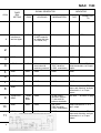
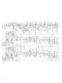
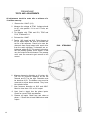
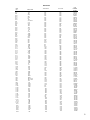
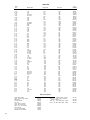
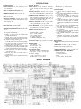
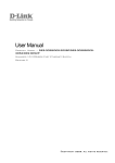
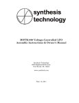
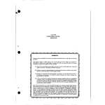
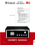
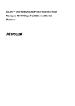
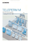
WARRANTY STATION
MAC 1500 STEREO RECEIVER
SERVICE MANUAL
CONTENTS
INTRODUCTION
1
FM ALIGNMENT CHART
2-3
MULTIPLEX DECODER ALIGNMENT CHART _ 4-5
SCHEMATIC
6-7
TESTS AND ADJUSTMENTS
8
DIAL STRINGING
PARTS
LIST
9-14
TOP AND BOTTOM VIEWS
15
SPECIFICATIONS
16
BLOCK DIAGRAM
16
AUDIO COMPANY
2 Chambers St., Binghamton, N.Y. 13903
MAC1500
McINTOSH
8
MAC 1500 STEREO RECEIVER
INTRODUCTION
All Mclntosh tuners are carefully aligned and tested at the factory using the finest
available test equipment. All Mclntosh tuners will meet their published specifications when shipped from the factory.
After extensive operation, especially when tubes have been replaced, it may be
desirable to realign the timer circuits for best performance. This manual gives
complete information on the circuit realignment procedure for the MAC 1500
receiver.
The test equipment listed below (or its equivalent) is necessary to properly
align a MAC 1500. The accuracy of the alignment will be directly related to the
accuracy and calibration of the test equipment used.
FM Signal Generator (Measurements 210A or equivalent)
VTVM
Multiplex Generator (RCA WR51A or equivalent)
10.7 MC Generator (Preferably crystal controlled)
Oscilloscope (Hewlett -Packard 120B or equivalent)
Harmonic Distortion Analyzer (Hewlett-Packard 330B or equivalent)
If the necessary test equipment is not available, alignment should not be
attempted. You may contact the Mclntosh Customer Service Department for
additional information.
Customer Service
Mclntosh Laboratory, Inc.
2 Chambers Street
Binghamton, New York
Our telephone number is 723-5491
The direct dial area code is 607
1
MAC 1500
STEPS
TUNER
DIAL
SETTING
SIGNAL GENERATOR
FREQ.
COUPLING
MODULATION
INDICATOR
TYPE
CONNECTED
TO
Point of no
interference
and no signal
10.7MC
Through external
.01 MFD capacitor
to mixer grid (pin
4 or 6DS4, V2)
cw
VTVM
TP#1
SAME
SAME
SAME
SAME
SAME
Pin 1 of T4
SAME
SAME
SAME
SAME
SAME
TP#2
105MC
105MC
300 ohm antenna
terminals with
matching network*
400 cycles
75KC deviation
(100% modulation)
VTVM connected to TP#2 and.
scope connected to L or R tape
output
5
90MC
90MC
SAME
SAME
SAME
6
105MC
105MC
SAME
SAME
SAME
7
90MC
90MC
SAME
SAME
SAME
90MC
90MC
SAME
SAME
VTVM connected to TP#2;
scope and distortion analyzer
connected to L or R tape
output
105MC and
90MC
105MC
and
90MC
SAME
50 cps 150KC
deviation Approx.
5 microvolts at
antenna terminals
See note ** at bottom of page
90MC
90MC
SAME
400 cycles
75KC deviation
(100% modulation)
Scope connected to L or R
tape output
90MC
90MC
SAME
SAME
VTVM connected to TP#1 ;
scope and distortion analyzer
connected to L or R tape
output
1
2
3
4
8
9
10
11
2
FM ALIGNMENT
ADJUST
TEST
LIMITS
REMARKS
Before making any adjustments, set the controls as follows:
a) Input selector switch to FM mono,
b) Volume control maximum CCW.
c) Muting pot maximum CW.
d) Muting OUT.
e) Stereo light adjust maximum CW.
Top (secondary)
and bottom
(primary) of
T1.T2, T3
Maximum possible negative
voltage
Shunt to ground the winding not being adjusted. Do this with a .01
MFD capacitor in series with a 1K resistor. Attenuate signal generator
until output voltage at TP#1 is less than 1.5 volts with one IF transformer winding shunted. IF transformers have terminal #1 marked
with a green dot and_ are numbered clockwise.
Primary and
secondary of
T4
Maximum possible negative
voltage (should
be 20 to 30
volts)
Muting pot. MUST be maximum CW.
Secondary
(top) of
T-5
Adjust for 0 volts
The primary (bottom) of T-5 should be adjusted only if a distortion
analyzer is available.
-4
Maximum negative voltage
L-4
SAME
Repeat steps 4 and 5 until dial calibration is accurate.
C-2, C-3
SAME
As output increases, attenuate signal generator to keep maximum output at TP#1 to less than 1 volt.
L-1, L-2, L3
SAME
Repeat steps 6 and 7 until output is as high as possible.
Primary (bottom)
of T-5
0.5% distortion
or less
Use a strong signal from the FM generator. Adjust T-5 primary for
minimum distortion. IF A DISTORTION ANALYZER IS NOT AVAILABLE,
OMIT THIS STEP. DO NOT ADJUST T-5 PRIMARY.
L-2, C-3
Minimum tilt
Observe direction of tilt of overall response curve at 105MC and 90MC.
If direction is the same, adjust L-2 at 100MC for minimum tilt. Re-check
tilt at 90MC and 105MC. If direction is not the same, adjust L-2 (at
90MC) and L-3 (at 105MC) for minimum tilt. Check tilt again at 100MC.
Muting threshold
control
With FM generator set for 2.5 microvolts output, place muting control
to "IN." Adjust the muting threshold control to the point at which the
sine wave on the scope becomes erratic.
IHFM Sensitivity
2.5 microvolts
for 3% total
noise and
distortion
Step 11 is an overall sensitivity check. It requires a distortion analyzer
and FM signal generator with attenuator. With 2.5 microvolts input at
the 300 ohm terminals, TP#1 voltage should be .45 volts or more.
3
MAC 15 00 MULTIPLEX
STEPS
TUNER
DIAL
SETTING
SIGNAL GENERATOR
FREQ.
COUPLING
MODULATION
INDICATOR
TYPE
CONNECTED
TO
Point of no
interference
or signal
Audio generTP#2
ator set to 67KC
0.5 volts output or less
Audio
VTVM
L or R tape output
SAME
MPX generator
with 19KC pilot
attenuated to
approx. 5%
level. (5% level
is ½ of normal
10% level).
19KC pilot
MUST be attenuated for
correct alignment
SAME
DC
VTVM
Pin 9 of 6EA8
100MC
100MC modulated by MPX
generator.
19KC pilot at
normal output
300 ohm
antenna terminals with
matching network. (See *
previous page)
1KC 100% modulation (34 KC
deviation) modulating left or
right only
Audio
VTVM
Pin 1 or 2 of T-7
SAME
SAME
SAME
SAME
Audio
VTVM
and
scope
L or R tape output
SAME
SAME
SAME
SAME
SAME
SAME
6
SAME
SAME
SAME
SAME
SAME
SAME
7
SAME
SAME
SAME
Turn off 1 KC audio
modulation
SAME
SAME
SAME
Tune to a strong
mono FM
station
SAME
1
2
3
4
5
8
4
MPX
stereo
indicator
light on
receiver
DECODER ALIGNMENT
ADJUST
TEST
LIMITS
REMARKS
67KC Trap (L-6)
Adjust for minimum voltage
Stereo light must be on. This is done by adjusting the "MPX Light Adj."
control, R-12.
T-6 top and
bottom;
L-5
Adjust for maximum voltage
Stereo light must be off.
•~
T-7 bottom core
SAME
Stereo light must be completely on.
T-7 top core
Adjust for stable
scope display
1. Turn off 19KC pilot on MPX generator.
2. Adjust upper core of T-7 to obtain a stable and uniform 1 KC signal
scope display. This adjustment may be critical, so turn core very
slowly.
3. Turn 19KC pilot back on.
L-5
30db separation
or more
Modulate left channel and measure right channel output. Adjust L-5 for
minimum right channel output (maximum separation). Be sure all test
leads are removed from TP#2 for separation tests.
SAME
Modulate right channel and measure left channel output. Separation in
steps 5 and 6 should be at least 30db.
This step checks the rejection of 19KC and 38KC frequencies. Residual output should be
at least 40db below modulated output.
MPX light adjust
control R-12
Turn control until light comes on. Then back off just enough to cause
the light to go off. Then back off about 1/8 of a turn more. Light should
operate ONLY on a MPX signal.
5
6
7
PREAMP/AMP
TESTS AND ADJUSTMENTS
All adjustments should be made after a minimum of a
10 minute warm-up.
1
Remove the 12AX7 (V-9).
2
Measure the voltage at TP#3. Voltage should
be 0.7 volts positive. If it is not 0.7 volts, adjust R-8.
3
Do likewise with TP#4 and R-9, TP#5 and
R-10, TP#6 and R-11.
4
Re-insert the 12AX7.
5 Feed a 1 KC signal into AUX. Drive the amp to
full 30 watts output. Be sure all controls are
set for a flat response. Check to be sure the
channels have equal output with equal drive
from the audio oscillator. If channels are unbalanced, adjust R-55, This control is found on
the left preamp printed circuit board. It will
vary the output of the left channel. The preamp
cover must be removed to gain access to this
control.
8
6
Measure harmonic distortion at 30 cycles. Adjust R-6 for minimum distortion on the left
channel and R-7 for the right. Distortion must
be less than 0.5%. The bottom cover must be
removed to adjust these controls. They have
blue plastic knobs.
7
Now measure distortion at 2KC and 20KC.
Must be less than 0.5% at full output.
8
Next, feed a signal thru the phono inputs.
Check for correct RIAA equalization.
9
Remove all inputs. Check hum and noise on
phono 1. Should be at least 60db below rated
output.
DIAL STRINGING
MAC 1500 PARTS LIST
TUBES
ITEM
NO.
USE
TUBE
NUMBER
PART
NUMBER
V-1
HF Amplifier
V-2
V-3
V-4
Mixer
1st IF Amplifier
2nd IF Amplifier
3rd IF Amplifier, 1st Limiter
4th IF Amplifier, 2nd Limiter
19KC Amplifier, Indicator Control
MPX 38KC Oscillator
Voltage Amplifier
Left Channel Driver
Right Channel Driver
Left Channel Output
Left Channel Output
Right Channel Output
Right Channel Output
6DS4
6DS4
6AU6
6AU6
6AU6
6CS6
6EA8
12AU7
12AX7
12AU7
12AU7
7591
7591
7591
7591
165-013
165-013
165-004
165-004
1 65-004
165-01 1
1 65-044
165-01 8
165-019
165-018
165-018
165-022
165-022
1 65-022
165-022
V-5
V-6
V-7
v-8
V-9
V-10
V-11
V-12
V-13
V-14
V-15
TRANSISTORS
ITEM
NO.
Q-1
Q-2
0-3
Q-4
Q-5
Q-6
Q-7
Q-8
Q-9
Q-10
Q-11
Q-12
Q-13
Q-14
Q-15
0-16
Q-17
Q-18
Q-19
Q-20
USE
Local Oscillator
Control Amplifier
MPX Lamp Control
Oscillator On-Qff Control
Left Channel Audio Amplifier
Right Channel Audio Amplifier
Left Channel Audio Amplifier
Right Channel Audio Amplifier
Left Channel Low Level Amplifier
Right Channel Low Level Amplifier
Left Channel Emitter Follower
Right Channel Emitter Follower
Left Channel Low Level Amplifier
Right Channel Low Level Amplifier
Left Channel Emitter Follower
Right Channel Emitter Follower
Left Channel Emitter Follower
Right Channel Emitter Follower
Left Channel Voltage Amplifier
Right Channel Voltage Amplifier
TRANSISTOR
NUMBER
PART
NUMBER
TA2556/40244
2N3638
1 32-008
132-007
132-010
132-004
1 32-004
132-004
1 32-004
132-004
132-004
132-004
132-004
132-004
1 32-002
132-002
1 32-004
132-004
132-004
132-004
132-002
1 32-002
2N3391A
2N3391A
2N3391A
2N3391A
2N3391A
2N3391A
2N3391A
2N3391A
2N3391A
2N720A
2N720A
2N339IA
2N3391A
2N3391A
2N3391A
2N720A
2N720A
DIODES
ITEM
NO.
D-1
D-2
D-3
D-4
D-5
D-6
0-7
D-8
D-9
D-10
D-11
D-12
D-13
D-14
D-15
D-16
DESCRIPTION
Diode
Diode
Diode
Diode
Diode
Diode [Matched pair 1N542)
Diode (Matched pair 1N542)
Diode (Matched pair 1N542]
Diode (Matched pair 1N542]
Diode (Matched pair 1N542]
800 PIV @ 750MA Silicon Rectifier
600 PIV @ 750MA Silicon Rectifier
600 PIV @ 750MA Silicon Rectifier
800 PIV @ 750MA Silicon Rectifier
400 PIV @ 750MA Silicon Rectifier
10 V @ 400 MW Zener Rectifier
DIODE
NUMBER
FD100
FD100
FD100
FD100
FD100
IN542
1N542
1N543
IN542
PART
NUMBER
070-022
070-022
070-022
070-022
070-022
070-003
070-003
070-003
070-003
070-003
070-017
070-016
070-016
070-017
070-015
070-011
9
CONTROLS
ITEM
NO.
R-1
R-2
R-3
R-4
R-5
R-6
R-7
R-8
R-9
R-10
R-11
R-12
R-55
FUNCTION
RESISTANCE
Balance Control
Bass Control
Treble Control
Volume Control
Muting Adjust Control
Driver Balance Control
Driver Balance Control
Bias Adjust Control
Bias Adjust Control
Bias Adjust Control
Bias Adjust Control
MPX Light Adjust Control
Left Channel Gain Control
500K-500K
IM-1M
500K-500K
60K-60K
100K
5K
5K
100K
100K
100K
100K
100K
5K
PART
NUMBER
134-165
134-117
134-118
134-164
134-102
134-103
134-103
134-102
134-102
134-102
134-102
134-102
134-120
SWITCHES
ITEM
NO.
S-1
FUNCTION
DESCRIPTION
Rotary Switch
SS-26 19/32 Trigger Slide Switch
SS-50 7/32 Trigger Slide Switch
SS-50 19/32 Trigger Slide Switch (S used)
Input Selector
Muting On -Off
Speaker On -Off
Stereo/Mono, Tape Monitor,
LF and HF Fillers, Loudness.
PART
NUMBER
1 46-096
148-003
148-006
1 48-007
TRANSFORMERS
ITEM
NO.
PART
NUMBER
FUNCTION
FM-IF
FM- IF
FM-IF
IF (Muting)
FM Discriminator
19KC Amplifier
38KC Oscillator
T-1
T-2
T-3
T-4
T-5
T-6
T-7
T-8
T-9
T-10
Ml
162-005
162-004
162-004
162-029
1 62-027
162-010
162-009
076-006
159-062
159-062
159-061
Balun
Output (Left)
Output (Right)
Power
CAPACITORS
ITEM
NO.
C-10
C-11
Variable FM
Trimmer (Ceramic)
Trimmer (Ceramic)
Trimmer (Glass)
Ceramic Disc.
Ceramic Disc.
Ceramic Disc.
Ceramic Feed -Thru
Ceramic Feed-Th r u
Ceramic Disc.
Ceramic Tubular
C-13
C-16
C-17
C-18
C-19
C-20
C-21
C-22
C-23
C-24
C-27
C-28
C-29
C-30
Ceramic Disc.
Ceramic Disc.
Ceramic Tubular
Ceramic Disc.
Ceramic Feed-Th ru
Ceramic Feed-Thru
Ceramic Feed-Thru
Ceramic Disc.
Ceramic Disc.
Ceramic Disc.
Ceramic Feed -Thru
Ceramic Feed-Thru
Ceramic Disc.
Ceramic Disc.
C-1
C-2
C-3
C-4
C-5
C-6
C-7
C-8
C-9
10
DESCRIPTION
CAPACITANCE
TOLERANCE
1-8 PF
1-8 PF
.005MFD
.001 MFD
.001 MFD
..001MFD
.001MFD
10PF
5PF
.005
10PF
3PF
10PF
.001 MFD
.001MFD
.001 MFD
..005MFD
10PF
.005 MFD
.001 MFD
.001MFD
.005MFD
.01 MFD
+80-20%
20% NPO
±.25PF
N150
+80-20%
20% NPO
±.25PF
20% NPO
+80—20%
20% NPO
+80-20%
+80-20%
+80-20%
PART
NUMBER
059-006
060-001
060-001
060-002
061-040
061-035
061-035
061-036
061-036
061-009
061-005
061-040
061-009
061-003
061-009
061-036
061-036
061-036
061-040
061-009
061-040
061-036
061-036
061-040
061-043
CAPACITORS
HEM
NO.
C-31
C-32
C-33
C-34
C-35
C-36
C-37
C-38
C-40
C-41
C-42
C-43
C-44
C-45
C-46
C-47
C-48
C-49
C-50
C-51
C-52
C-53
C-54
C-55
C-56
C-57
C-58
C-59
C-60
C-61
C-62
C-63
C-64
C-65
C-66
C-67
C-68
C-69
C-70
C-71
C-72
C-73
C-74
C-75
C-76
C-77
C-7B
C-79
C-80
C-81
C-82
C-83
C-84
C-85
C-86
C-87
C-88
C-89
C-90
C-91
C-92
C-93
C-94
C-95
C-96
C-97
C-98
C-99
C-100
C-101
C-102
C-103
C-104
C-105
C-106
C-107
C-108
C-109
C-110
C-111
C-112
C-113
DESCRIPTION
CAPACITANCE
Ceramic Disc.
Ceramic Disc.
Ceramic Disc.
Ceramic Disc.
Ceramic Disc.
Ceramic Tubular
12PF
.1MPD
.005MFD
.005MFD
.01 MFD
Flat Foil
Ceramic Feed-Thru
Ceramic Feed-Thru
Ceramic Feed-Thru
Ceramic Feed-Thru
Ceramic Disc.
Ceramic Disc.
Ceramic Disc.
Ceramic Disc.
Ceramic Disc.
Ceramic Disc.
Ceramic Feed -Thru
Ceramic Disc.
Silver Mica
Ceramic Disc.
Ceramic Disc,
Ceramic Disc.
Ceramic Disc.
Silver Mica
Silver Mica
Electrolytic
Ceramic Disc.
Ceramic Disc.
Silver Mica
Silver Mica
Ceramic Disc.
Ceramic Disc.
Ceramic Disc.
Ceramic Disc.
Ceramic Disc.
Ceramic Disc.
Ceramic Tubular
Ceramic Tubular
Ceramic Disc.
Ceramic Disc.
Flat Foil
Flat Foil
Ceramic Disc.
Flat Foil
Flat Foil
Ceramic Disc.
Ceramic Disc.
Electrolytic
Electrolytic
Ceramic Disc.
Ceramic Disc.
Ceramic Disc.
Ceramic Disc.
Ceramic Tubular
Ceramic Tubular
Flat Foil
Flat Foil
Flat Foil
Flat Foil
Molded Film
Molded Film
Electrolytic
Electrolytic
Mylar
Mylar
Ceramic Disc.
Ceramic Disc.
Flat Foil
Flat Foil
Electrolytic
Electrolytic
Ceramic Disc.
Ceramic Disc.
Mylar
Mylar
Mylar
Mylar
Mylar
.1MFD
.001 MFD
.001 MFD
.001 MFD
.001 MFD
.1MFD
.005MFD
.005MFD
6.8PF
12PF
47PF
100PF
.02MFD
.0027MFD
100PF
.001MFD
.001MFD
.02MFD
.0012MFD
.0012MFD
100MFD
_1MFD
220PF
.0047MFD
.0047MFD
.005MFD
.005MFD
.005MFD
.005MFD
330PF
330PF
430PF
430PF
.01 MFD
.01 MFD
.22MFD
.22MFP
10PF
.22MFD
.22MFD
.1MFD
.1MFD
100MFD
100MFD
.1MFD
.1MFD
.0012MFD
.0012MFD
430PF
430PF
.22MFD
.22MFD
.22MFD
.22MFD
.22MFD
.22MFD
100MFD
100MFD
.47MFD
.7MFD
.0015 MFD
.0015MFD
.047MFD
.047MFD
100MFD
100MFO
47PF
47PF
.25MFD
.25MFD
.1MFD
.1MFD
.1MFD
.1MFD
430 PF
430PF
Mylar
Ceramic Tubular
Ceramic Tubular
VOLTAGE
15PF
40V
100V
100V
100V
3V
40V
40V
40V
40V
TOLERANCE
20% NPO
+80-20%
+80-20%
+80—20%
+80-20%
±.75PF
N150
20%
+80-20%
+80-20%
+80-20%
20% NPO
20% NPO
20% N470
20%
+80-20%
5%
10% N1500
+80-20%
5%
5%
+80-20%
20%
5%
5%
+80-20%
+80-20%
+80—20%
+80-20%
10%
10%
5%
5%
+80—20%
+80-20%
20%
20%
20% NPO
20%
20%
+80-20%
+80-20%
12V
12V
40V
40V
40V
40V
200V
200V
12V
12V
100V
10CV
40V
40V
3V
3V
400V
400V
600V
600V
600V
600V
+80-20%
+80-20%
10%
10%
5%
5%
20%
20%
20%
20%
20%
20%
10%
10%
10%
10%
20%
20%
20% N470
20% N470
10%
10%
10%
10%
10%
10%
5%
5%
PART
NUMBER
061-010
061-049
061-040
061-040
061-043
061-012
064-027
061-036
061-036
061-036
061-036
061-049
061-040
061-040
061-008
061-010
061-019
061-021
061-045
063-004
061-023
061-035
061-035
061-045
063-002
061-002
066-047
061-049
061-028
063-005
063-005
061-040
061-040
061-040
061-040
061-029
061-029
061-031
061-031
061-043
061-043
064-024
064-024
061-009
064-024
064-024
061-049
061-049
066-018
066-018
061-049
061-049
061-051
061-051
061-031
061-031
064-024
064-024
064-024
064-024
064-013
064-013
066-018
066-018
064-019
064-019
061-038
061-038
064-036
064-036
066-047
066-047
061-019
061-019
064-016
064-016
064-012
064-012
064-012
064-012
061-031
061-031
11
CAPACITORS
ITEM
NO,
DESCRIPTION
CAPACITANCE
VOLTAGE
C-119
C-120
C-121
C-122
C-123
C-124
Mylar
Mylar
Ceramic Disc.
Ceramic Disc.
Mylar
Electrolytic
Electrolytic
Tubular
Tubular
Tubular
Electrolytic
C-125
C-126
C-127
C-128
C-129
C-130
C-131
C-132
Ceramic Disc.
Ceramic Feed-Thru
Ceramic Disc.
Fixed Composition
Fixed Composition
Ceramic Tubular
Ceramic Disc.
Ceramic Tubular
.1MFD
.1MFD
.005MFD
.005MFD
.47MFD
60-40MFD
40-40-40 MFD
50MFD
100MFD
50MFD
50-50-5050MFD
.001 MFD
.001 MFD
.005MFD
.18PF
.18PF
430PF
.02MFD
5PF
C-133
Ceramic Disc.
Ceramic Disc.
Ceramic Disc.
1SOPF
150PF
4.7PF
C-114
C-115
C-116
C-117
C-118
C-134
C-135
TOLERANCE
125V
125V
10%
10%
1400V
1400V
200V
500V-500V
450V-300V- 150V
50V
12V
50V
200V-200V200V-200V
10%
+80-20%
10%
10%
5%
+80-20%
±.25PF
N220
20%
20%
20% NPO
PART
NUMBER
064-028
064-028
061-052
061-052
064-020
066-026
066-032
066-014
066-018
066-014
066-036
061-035
061-036
061-040
069-001
069-001
061-031
061-045
061-007
061-025
061-025
061-004
COILS
ITEM
NO.
DESCRIPTION
Antenna Coil
R.F. Coil
Mixer Coil
OSC. Coil
Peaking Coil
Filter Coil
Neutralizing Choke
Parasitic Choke
RF Choke
RF Choke
RF Choke
RF Choke
RF Choke
RF Choke
RF Choke
RF Choke
RF Choke
RF Choke
Peaking Coil
Filter Coil
Filler Coil
L-1
L-2
L-3
L-4
L-5
L-6
L-7
L-8
L-9
L-10
L-11
L-12
L-13
L-14
L-15
L-16
L-17
L-16
L-19
L-20
L-21
PART
NUMBER
VALUE
19KC
67KC Trap
2.5 Micro H 3%
1.2 Micro H
1.2 Micro H
1.2 Micro H
1.2 Micro H
1.2 Micro H
1.2 Micro H
1.2 Micro H
1.2 Micro H
1.2 Micro H
75 Micro H
38 Micro H
Lo Pass
Lo Pass
122-035
1 22-054
1 22-055
1 22-056
122-008
122-009
122-033
122-028
122-011
122-011
122-011
122-011
122-011
122-011
122-011
122-011
122-011
122-013
122-014
122-015
122-015
RESISTORS
ITEM
NO.
R-13
R-14
R-15
R-16
R-17
R-16
R-19
R-20
R-21
R-22
R-23
R-24
R-25
R-26
R-27
R-2S
R-29
R-30
R-31
R-32
R-33
R-34
R-35
12
RESISTANCE
TOLERANCE
WATTAGE
47K
100 ohms
15K
3.3K
220 ohms
10%
10%
10%
10%
10%
10%
10%
10%
10%
10%
10%
10%
10%
10%
10%
10%
10%
10%
10%
10%
10%
10%
10%
¼W
1K
470 K
1M
100 ohms
1K
100 ohms
10K
10M
47K
470 K
100K
1K
6.8 K
220K
470K
47K
470K
2.2K
½w
¼W
¼W
¼W
½W
¼W
½W
½W
½W
½W
½W
½W
¼W
¼W
½W
½W
½W
¼W
¼W
½W
¼W
½W
PART
NUMBER
136-339
136-068
136-377
136-385
136-396
136-110
136-373
136-236
136-068
136-110
136-068
136-152
136-278
136-339
136-222
136-301
136-110
136-145
136-372
136-373
136-180
136-373
136-124
RESISTORS
ITEM
NO.
RESISTANCE
TOLERANCE
R-36
R-37
R-38
R-39
R-40
H-41
R-42
R-43
R-44
R-45
R-46
R-47
R-48
R-49
R-50
R-S1
R-52
R-53
R-54
R-60
R-61
R-62
R-63
R-64
R-65
R-66
R-67
R-68
R-69
R-70
R-71
R-72
R-73
R-74
R-75
R-76
R-77
R-78
R-79
R-80
R-81
R-82
R-83
R-84
R-85
R-86
R-87
R-88
R-89
R-90
R-91
R-92
R-93
H-94
R-95
R-96
R-97
R-98
R-99
R-100
R-101
R-102
R-103
R-104
R-105
R-106
R-107
R-108
R-109
R-110
R-111
R-112
R-113
R-114
R-115
R-116
R-117
R-118
R-119
R-120
R-121
R-122
R-123
220 ohms
10K
10K
22 K
39K
2.2K
IK
1M
470 ohms
4.7K
2.7 K
1M
1M
1M
4.7K
1.2K
1K
4.7K
100K
220K
100K
6.8K
22K
47K
47K
47K
47K
150K
150K
1M
1M
4.7M
4.7M
6.8 K
6.8K
1.8K
I.8K
470K
470K
1M
1M
4.7M
4.7M
1K
1K
1M
1M
1.2K
1.2K
100K
100K
27K
27K
220K
220K
680 ohms
630 ohms
15K
15K
3.3M
3.3M
I30K
180K
47K
47K
22K
47K
22K
47K
47K
47K
1M
1M
1M
1M
27K
27K
100K
100K
470K
470K
18K
18K
10%
10%
10%
10%
10%
10%
10%
10%
10%
10%
10%
10%
10%
10%
10%
10%
10%
10%
J0%
10%
10%
10%
10%
10%
10%
10%
10%
5%
5%
10%
10%
10%
10%
10%
10%
10%
10%
10%
10%
10%
10%
10%
10%
10%
10%
10%
10%
5%
5%
10%
10%
10%
10%
10%
10%
10%
10%
10%
10%
10%
10%
5%
5%
10%
10%
10%
10%
10%
10%
5%
5%
10%
10%
10%
10%
10%
10%
10%
10%
10%
10%
10%
10%
WATTAGE
½W
¼W
¼W
½W
¼W
¼W
½W
¼W
¼W
¼W
¼W
¼W
¼W
½W
¼W
½W
¼W
¼W
¼W
¼W
¼W
½W
¼W
¼W
¼W
¼W
¼W
¼W
¼W
¼W
¼W
¼W
¼W
¼W
¼W
¼W
¼W
¼W
¼W
¼W
¼W
¼W
¼W
¼W
¼W
¼W
¼W
¼W
¼W
¼W
¼W
¼W
¼W
¼W
¼W
¼W
¼W
¼W
¼W
¼W
¼W
¼W
¼W
¼W
¼W
¼W
¼W
¼W
¼W
¼W
¼W
¼W
¼W
¼W
¼W
¼W
¼W
¼W
¼W
¼W
¼W
¼W
¼W
PART
NUMBER
136-082
136-382
136-382
136-166
136-370
136-367
136-110
136-303
136-295
1 36-298
136-297
136-303
136-303
136-236
1 36-298
136-114
1 36-296
136-298
136-301
136-372
136-301
136-145
136-369
136-339
136-339
136-339
1 36-339
136-371
136-371
136-303
136-303
1 36-374
136-374
136-368
136-368
136-381
136-381
136-373
136-373
136-303
1 36-303
136-374
136-374
136-296
136-296
136-303
1 36-303
1 36-394
136-394
136-301
136-301
136-379
136-379
136-372
1 36-372
136-378
136-378
136-377
136-377
136-380
136-380
1 36-387
136-387
136-339
136-339
136-369
1 36-339
1 36-369
136-339
136-388
136-388
136-303
136-303
136-303
136-303
136-379
136-379
136-301
136-301
136-373
136-373
136-386
136-386
13
RESISTORS
ITEM
NO.
RESISTANCE
R-124
R-125
R-126
R-127
R-128
R-129
R-130
H-131
R-132
R-133
R-134
R-135
R-136
R-137
R-J3S
R-139
R-140
R-141
R-142
R-143
R-144
R-145
R-146
R-147
R-148
R-149
R-150
R-151
R-152
R-153
R-151
R-155
R-156
R-157
R-158
R-159
R-160
R-161
R-162
R-163
R-164
R-165
R-166
R-167
R-168
R-169
R-170
R-171
R-172
R-173
R-174
R-175
R-176
R-177
R-178
R-179
R-180
7.5K
4.7K
7.5K
4.7K
150 ohms
150 ohms
5.6K
5.6K
3.3K
3.3 K
100 ohms
100 ohms
330K
330K
15K
15K
1.2M
1.2M
18K
18K
27K
27K
30K
30K
220K
220K
220K
220K
22K
4.7K
4.7K
4.7K
4.7K
1 5 ohms
1 5 ohms
15 ohms
15 ohms
1.8K
1.8K
47 ohms
47 ohms
2.2M
900 ohms
3.6 K
33 K
33K
MSI
1K
470K
27K
27K
1M
1M
1K
10K
100 ohms
1K
470K
R-182
R-183
R-184
R-185
R-186
R-187
R-188
R-189
R-190
R-191
TOLERANCE
WATTAGE
5%
10%
5%
10%
10%
10%
5%
5%
10%
10%
5%
5%
10%
10%
10%
10%
10%
10%
10%
10%
10%
10%
5%
5%
10%
10%
10%
10%
10%
10%
10%
10%
10%
5%
5%
5%
5%
5%
5%
20%
20%
10%
10%
10%
10%
10%
10%
10%
10%
10%
10%
10%
10%
20%
10%
10%
10%
10%
10%
10%
10%
10%
10%
10%
10%
10%
10%
10%
6K
6K
8.2K
18K
220 ohms
220 ohms
220 ohms
1.5K
1M
1M
1K
¼W
¼W
¼W
¼W
¼W
¼W
¼W
¼W
½W
½W
½W
½W
½W
½W
½W
½W
½W
½W
1W
1W
1W
1W
1W
1W
¼W
¼W
¼W
¼W
½W
½W
½W
½W
½W
1W
1W
1W
1W
½W
½W
2W
2W
½W
5W
5W
½W
½W
5W
5W
1W
½W
5W
5W
5W
2W
¼W
¼W
½W
½W
½W
¼W
¼W
¼W
¼W
½W
¼W
½W
¼W
¼W
PART
NUMBER
136-376
136-298
136-376
1 36-298
136-294
136-294
136-397
136-397
136-131
136-131
136-067
136-067
136-215
136-215
136-159
136-159
136-240
1 36-240
136-313
136-313
136-316
136-316
136-317
136-317
1 36-372
136-372
136-372
136-372
136-166
136-138
136-138
136-138
136-138
1 39-034
1 39-034
139-034
139-034
136-120
136-120
1 36-323
1 36-323
136-250
139-012
139-013
136-173
136-173
139-033
139-033
136-31 1
136-163
1 39-009
139-009
139-009
136-329
136-303
136-303
136-110
136-110
136-222
136-379
136-379
136-303
136-303
136-110
136-382
1 36-068
136-296
136-373
MISCELLANEOUS
Lamp, MPX #1850
Lamp, Incandescent #1866
Dial Glass
Extrusion Glass
End Cap
Lower Panel Extrusion
Upper Panel Extrusion
Fuse — 3.2 Amp Slo-Blo
Tuning Meter
Tone Control Module
Rumble and HF Module
14
058-006
058-014
016-052
016-053
018-080
018-094
018-095
089-006
124-006
130-007
130-025
Knob (¼ " without index) Tuning
Knob (11/8 " with index) Volume,
Selector , Balance
Knob (11/8 " with index) Bass, Treble
Knob (¾" with index) Bass, Treble
043-479
043-480
090-070
090-071
MAC
V 15
V 14
1500
V13
TOP
BIAS ADJUST
CONTROLS
and
V12
BOTTOM
V3
VIEWS
V4
OUTPUT
TRANSFORMERS
POWER
TRANSFORMER
LEFT
RIGHT
V10
V9
OSCILLATOR
V11
COIL
TRIMMER
V2
MIXER
COIL
12AU7 (V8)
TRIMMER
6EA8 (V7)
LEFT AND RIGHT
PRE AMP PRINTED
CIRCUIT BOARDS
TRIMMER
COIL
V1
V4
MUTE ADJUST CONTROL
ANTENNA
COIL
V12
RF
TUNING CONDENSER COVER
V13
V14 V15
3RD IF TRANSFORMER
4TH IF TRANSFORMER
V5
2ND IF TRANSFORMER
Q3
Q4
Q2
2.2K
V6
1ST IF TRANSFORMER
DISCRIMINATOR
TRANSFORMER
19KC
PHASE COIL
INJECT 10.7 MC
Q7
SIGNAL HERE
Q5
Q8
Q6
MPX INPUT
(WHITE WIRE;
19 KC TRANSFORMER
LOW PASS FILTER
ANTENNA COIL
67 KC FILTER
RF COIL
MIXER COIL
38 KC TRANSFORMER
15
SPECIFICATIONS
FM TUNER SECTION:
AMPLIFIER SECTION:
USABLE SENSITIVITY lot 100% modulation): 2.5uV
(I.H.F. Standards)
POWER OUTPUT: 60 watts continuous, 30 watts per
channel, 65 watts total music power (I.H.F. Standards).
SIGNAL TO NOISE AND HUM RATIO: 65db.
HARMONIC DISTORTION: Mono, less than .5%
Stereo, less than .8%
DRIFT: less than 25KC
FREQUENCY RESPONSE: Flat from 20 cps to 20KC
with standard 75 µ second deemphasis and 19KC
pilot frequency filter.
CAPTURE RATIO: Better than 2.0db.
IMAGE REJECTION: Better than 60db.
STEREO MULTIPLEX SEPARATION: Better than 30db
at 1 KC.
SPECIAL FEATURES:
a) Automatic stereo switching.
b) Muting: IF Injected circuit with at least 50db
quieting between stations.
c) Antenna inputs for 300 ohm balanced (for twin
lead) and 75 ohm unbalanced (for coaxial cable).
d) Nuvistor RF amplifier, Nuvistor mixer.
e] Four stages of IF amplification, with AGC used to
insure that limiting occurs only in the limiter stages.
f) Two limiter stages used for exceptional capture
ratio and smooth muting operation.
g) Multiplex filter and SCA filter, to suppress 19KC
and 38KC signal components at least 40db below
program and to suppress 67KC SCA by 60db.
h) Noise immune logic circuit used to activate MPX
stereo light and automatic stereo switching on
19KC stereo pilot only.
i) D'Arsonval tuning meter lor accurate center of
channel tuning.
i) Flywheel tuning for ease of operation and precise
tuning.
HARMONIC DISTORTION: less than 0.5% 30 cps to
20KC, both channels operating at rated output at
the same time.
INTERMODULATION DISTORTION: Less than 0.5%
for any combination of frequencies from 30 cps to
20KC at rated output (equivalent RMS watts). I.M.
decreases as output power is reduced.
FREQUENCY RESPONSE: ±0.5db 20 cps to 20KC.
(Power amplifier response is 2 cps to 150KC at
— 3db; power bandwidth is 19 cps to 30KC.)
OUTPUT IMPEDANCE: 4, 8, and 16 ohms. Rated output is delivered by any of these impedances.
DAMPING FACTOR: Greater than 1 0.
INPUT SENSITIVITY AND IMPEDANCE:
Tape Head—2.8MV, 1 megohm
Phono 1 —5.6MV, 47K ohms
Phono 2-2.8MV, 47K ohms
Aux—400MV, 500K ohms
Tape Monilor-400MV, 500K ohms
TAPE OUTPUT LEVEL: Tuner-1.2 volts, for other Inputs
400MV at rated sensitivity.
HUM AND NOISE:
Power Amplifier, — 90db
High Level Inputs, - 75db
Low Level Inputs, —60db
H.F. Filler, cutoff frequency = 5KC.
attenuation rale = 1 2db per octave
SPECIAL FEATURES:
a) Loudness control for full fidelity listening
levels.
b) Tape monitor switch for listening to recorded tope
program white recording.
c) Tone controls are "clutched" for tracking operation of left and right channels or independent
operation.
d) Headphone output fed from special tap on output
transformer for maximum signal to noise ratio.
Speakers may be automatically muted when headphone plug is inserted, by use of rear mounted
switch.
e) Silicon transistors used in all preamplifier stages
for low noise and hum free operation.
f) High quality epoxy circuit boards for reliable long
life performance.
g) High quality conservatively operated components
ore used throughout for long life.
h) Zener regulated power supply is used for critical
circuits.
i) Equalization and tone control circuits are feedback type for lowest distortion and greatest accuracy.
MISCELLANEOUS
FINISH: Gold anodized panel and knobs, black finished
chassis.
DIMENSIONS: 16" wide, 5½" high, 16" deep.
WEIGHT: 40 lbs., shipping weight 54 Ibs.
TONE CONTROL RANGE:
Bass control + 1 5db to - 1 8db at 50 cps.
Treble control + 1 5db to - 1 5 db at 10KC.
L.F. and H.F. FILTER:
L.F. filter, cutoff frequency = 50 cps,
attenuation rate — 1 2db per octave
POWER CONSUMPTION: 180 watts, 120 volts, 60 cps.
TRANSISTOR AND TUBE COMPLEMENT:
19 silicon transistors
1 germanium transistor
15 tubes
1 6 diodes, rectifier, and zener diode
BLOCK DIAGRAM
16
MAC 1500 STEREO
RECEIVER
BLOCK DIAGRAM
MclNTOSH AUDIO COMPANY
2 Chambers St., Binghamton, N.Y. 13903
Made In U.S.A.
Phong—Area Code 607-723-5491
Design subject to change without notice.
Printed in U.S.A.
038-133
BE062003