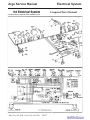
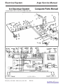
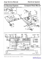
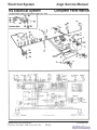
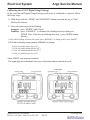
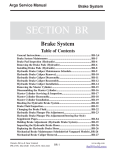
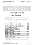
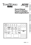
1
Argo Service Manual Electrical System SECTION ES Electrical System Table of Contents General Instructions............................................................................. ES-5 Battery.................................................................................................... ES-6 Checking Battery Fluid Level.............................................................. ES-6 Charging the Battery.............................................................................ES-6 Cleaning the Battery Terminals & Cable Connections......................ES-6 Cleaning the Battery..............................................................................ES-7 Battery Removal.................................................................................... ES-7 Battery Inspection................................................................................. ES-7 Battery Installation............................................................................... ES-8 Changing a Headlamp Bulb (Earlier Conquest Models)...................ES-8 Installing the Headlamp Bulb (Earlier Conquest Models)................ES-9 Removing a Headlamp Bulb................................................................ES-9 Installing a Headlamp Bulb..................................................................ES-10 Removing the Headlamp Lens Assembly (Conquest Models From CB12580).................................................... ES-10 Installing the Headlamp Lens Assembly (Conquest Models From CB12580)......................................................ES-11 Headlamp Removal (Earlier Vanguard2 & Vanguard 6x6)..............ES-11 Headlamp Installation (Earlier Vanguard2 & Vanguard 6x6)......... ES-11 Headlamp Removal (Response, Bigfoot & Later Vanguard2 and Vanguard 6x6)............ ES-12 Headlamp Installation (Response, Bigfoot & Later Vanguard2 and Vanguard 6x6)............ ES-12 Ontario Drive & Gear Limited PH.(519)- 662-2840 FAX (519)- 662-2421 www.odg.com ES-1 Electrical System Argo Service Manual SECTION ES Electrical System Table of Contents Removing the Starter (Conquest Models).......................................... ES-13 Installing the Starter (Conquest Models)............................................ES-14 Removing the Starter (Response, Bigfoot, Vanguard2 & Vanuard Models)......................... ES-14 Installing the Starter (Response, Bigfoot, Vanguard2 & Vanguard Models)....................... ES-16 Removing the Brake Cooling Fan (Response & Bigfoot).................. ES-17 Installing the Brake Cooling Fan (Response & Bigfoot).................. ES-18 Removing the Brake Cooling Fan (Conquest).................................... ES-19 Installing the Brake Cooling Fan (Conquest)..................................... ES-20 Wiring Diagrams and Schematics Models T, TB, HT, HTB From 1977; KB From 1981-86; K From 1983 S From 1986; SB From 1987;..........................................ES-22, 23 Argo Standard & Heavy Duty (Models V688-20,V888-20, V888-21; After T6460, TB8446, HTB8592 11/88).................................ES-23 Argo Twin (Model V888-22, V688-22 From SB8355, S6308).............ES-24 Argo Vanguard Model V891/892-22, V691/692-22 From S6834, SB9691..............................................................................ES-25 Argo Model NKB From 1987 1/87......................................................ES-26 Ontario Drive & Gear Limited PH.(519)- 662-2840 FAX (519)- 662-2421 www.odg.com ES-2 Argo Service Manual Electrical System Argo I/C Model V888-23, V688-23 From NKB 8187, NK 6192 11/88...........................................................ES-27 Argo Magnum Model V890-23, V690-23 12/89...................................ES-28 Argo Magnum Model V890-23, V690-23 From NKB9466, NK 6812 10/90............................................................ES-29 Argo Magnum Model V891-23 From NKB 10785; Models V891-27, V691-27 06/93...........................ES-30 Argo Magnum Model V894-23, V894-27 From NKB 10973 03/94....ES-31 Response Model V896-65 From RB 12075 08/95.................................ES-32 Response Model V896-65 From RB 12702 11/96.................................ES-33 Response Model V896-65 From RB 14121 10/97................................ES-34 Reponse Model V899-65 From RB 16104 06/99..................................ES-35 Response Model V899-65 From RB 17665 12/00.................................ES-36 Conquest V894-37, V894-38 From CB 10847 01/94............................ES-37 Conquest Model V894-37, V894-38 From CB 12580 03/96................ES-38 Conquest Model V899-37, V899-38 From CB 16049 05/99................ES-39 Conquest Model V899-37, V899-38 From CB 17857 02/01................ES-40 Argo Vanguard Model 693-22 From S6999 02/92..............................ES-41 Argo Vanguard Model V693-36 From S7304 06/93............................ES-42 Argo Vanguard Model V697-51 From S8131 09/97............................ES-43 Argo Vanguard Parts Manual Model V699-51 From S12222 03/02................................................................................ES-44 Ontario Drive & Gear Limited PH.(519)- 662-2840 FAX (519)- 662-2421 www.odg.com ES-3 Electrical System Argo Service Manual Argo Vanguard2 Model V696-55 From SN7841 04/95..................... ES-45 Argo Vanguard2 Model V697-55 From SN8138 11/95......................ES-46 Argo Vanguard2 Model V697-55 From SN8138 11/95......................ES-47 Argo Vanguard2 Model V699-55 From SN12227 02/01................... ES-48 Bigfoot Model V698-58 From BF9212 08/97......................................ES-49 Bigfoot Model V698-58 From BF12097 12/00...................................ES-50 Conquest 6x6 Model V601-62 From C12747 11/01........................... ES-51 Ontario Drive & Gear Limited PH.(519)- 662-2840 FAX (519)- 662-2421 www.odg.com ES-4 Argo Service Manual Electrical System General Instructions Detailed information on standard workshop and safety procedures, and general servicing operations is not included in this manual, which has been prepared to assist qualified service personnel. ODG assumes no responsibility or liability for PERSONAL INJURY or VEHICLE DAMAGE which results from any servicing procedure performed, including those instructions outlined in this manual. Before performing a servicing operation, an individual must have determined to his/her satisfaction that a personal injury or vehicle damage will not result from the servicing procedure or tools selected. To prevent damage to the electrical system: • Always disconnect the battery when servicing any electrical component. • Never weld on the vehicle without first disconnecting both positive and negative battery cables. Make sure the part you are welding is properly grounded. • Connecting booster cables to start your vehicle is not a recommended practice. Damage to engine electrical components could occur. • Connect switch terminals properly, especially the ground wire. Battery fluid contains sulphuric acid. If battery fluid comes in contact with skin or eyes, flush thoroughly with water. If swallowed, call physician or poison control centre immediately. KEEP AWAY FROM CHILDREN. Serious personal injury can occur. Always wear rubber gloves and safety glasses when servicing the battery. Batteries can explode and cause serious personal injury if exposed to flame or sparks. Never smoke while servicing the battery. Ontario Drive & Gear Limited PH.(519)- 662-2840 FAX (519)- 662-2421 www.odg.com ES-5 Electrical System Argo Service Manual Battery All models are equipped with a 12 volt, wet cell type battery. The battery is located in the engine compartment, on the right side in front of the driver’s position. Checking the Fluid Level Check the fluid level every 50 hours of operation. Remove the pod vents and make sure each cell is filled to the fluid level as shown in Fig ES-1. If the fluid has dropped below the fill well, add distilled water until the cell is filled to correct level. DO NOT OVERFILL. Charging the Battery Fill all new dry charged batteries with electrolyte battery acid and let stand (off cement floor) for 6 hours. Slow charge for at least another 6 hours. ES-1 If the battery loses its electrical charge, remove the battery from the ARGO and recharge it with a 12 volt battery charger at the rate of 1012 amps maximum. The battery should remain on charge until the specific gravity reaches 1.265 on a hydrometer. Re-install the battery in the vehicle and try to start the engine. If the battery fails to perform properly, have it tested by a battery service dealer. Replace a defective battery immediately. Ventilate area when charging. Keep away from spark, heat, cigarettes or open flame. Cleaning the Battery Terminals and Cable Connections Clean the battery terminals and cable connections every 100 hours. Remove the black NEGATIVE (-) cables first. Make sure you reconnect the NEGATIVE (-) cables to the NEGATIVE (-) post and the red POSITIVE (+) cables to the POSITIVE (+) posts. Damage to the electrical system will occur if the cables are reversed. Ontario Drive & Gear Limited PH.(519)- 662-2840 FAX (519)- 662-2421 www.odg.com ES-6 Argo Service Manual Electrical System Cleaning the Battery Clean the top of the battery every 250 hours with a mixture of baking soda and water. Before cleaning the battery, remove it from the vehicle and make sure the pod vents are in place. Soak a cloth in the soda/water mixture and scrub the top of the battery. After the foaming has stopped, flush with clean water and dry with a clean cloth. Battery Removal 1. Perform the servicing procedure, Removing the Firewall, in section VB of this service guide. 2. Locate the battery on the right hand side of the vehicle. 3. Remove the negative battery cable first. Accessing the negative ground cable terminal on Conquest models may require removing the battery retaining bracket first, then sliding the battery partially out to loosen the terminal hardware. 4. Slide the battery out through the firewall area. Battery Inspection 1. Inspect the battery for: • cracks in the battery casing • cracked or broken terminals • exposed or corroded cells • weak cells 2. Inspect the Battery for: • corroded terminals • low water level If any of these conditions are noted, service the battery immediately. Adjust battery fluid level with distilled water, and clean and grease the battery terminals. Ontario Drive & Gear Limited PH.(519)- 662-2840 FAX (519)- 662-2421 www.odg.com ES-7 Electrical System Argo Service Manual Battery fluid contains sulphuric acid. If it comes into contact with your skin or eyes, serious personal injury will occur. Always wear rubber gloves and safety goggles when servicing the battery. Batteries produce explosive gas. Keep sparks, flames and cigarettes away from the battery. Re-charge the battery only in a well ventilated area. Keep the battery charged. Never allow the battery to become drained by unnecessary use of the headlights or overcranking of the engine. If the battery is dead or the electrical charge is low, re-charge it with a 12 volt battery charger. Slow charge for at least 6 hrs. If persistant problems with battery charge occur, before replacing the battery, ensure that the engine charging system is functioning properly. Refer to the appropriate engine service manual given in section GI of this service guide. Battery Installation 1. Place the battery on to the battery frame. Install the battery retaining bracket and fasten securely. 2. Fasten the main power cable to the positive battery terminal. 3. Reattach the ground cable to the negative terminal side of the battery. 4. Reinstall the firewall. Changing a Headlamp Bulb (Earlier Conquest Models) On vehicles manufactured prior to CB12581: 1. Remove the hood and disconnect the battery. 2. Locate the the fastener above the headlamp and remove. The fastener is threaded to a nut on the underside of the headlamp mounting bracket. Carefully unthread the bolt while holding the nut with your finger, preventing it from falling into the vehicle. Ontario Drive & Gear Limited PH.(519)- 662-2840 FAX (519)- 662-2421 www.odg.com ES-8 Argo Service Manual Electrical System 3. Pull the headlamp assembly from the vehicle. Unwrap the electrical tape from the power wire and disconnect. 4. Disconnect the ground wire at the headlamp mounting bracket. 5. Remove the trim screws and separate the lens from the headlamp housing. 6. Remove the bulb. Installing the Headlamp Bulb (Earlier Conquest Models) When installing the new bulb, avoid any contamination of the glass surface. Do not touch the bulb with your fingers. 7. Secure the bulb inside the housing and route the power wire through the rubber grommet at the bottom of the assembly. 8. Assemble the lens back to the housing. Ensure that the gasket is in place and not damaged. Replace if necessary. 9. Install the screws to the headlamp trim. 10. Plug the power wire leading from the new bulb, into the vehicle wire harness. Retape the connection with electrical tape. 11. Place the headlamp assembly back into the upper body, aligning the hole of the headlamp mounting bracket, with the hole in the top of the upper body. 12. Secure with the bolt and nut. Re-connect the battery. Although replacement bulbs are still available for this headlamp, the lens and housing assembly is not. If the entire assembly needs replacing, an update kit is available to adapt the newer style headlamp to an older vehicle. Removing a Headlamp Bulb On Vehicles manufactured from CB12581, RB12075, S8131, SN8138 BF9121 & C12747: 1. Remove the engine hood assembly. 2. To remove the bulb from the lens, reach into the engine compartment and turn the bulb 1/4 turn counter-clockwise. Pull straight out. Photo ES-2 Ontario Drive & Gear Limited PH.(519)- 662-2840 FAX (519)- 662-2421 www.odg.com ES-9 Electrical System Argo Service Manual ES-2 3. ES-3 Disconnect the bulb from the lens. Pry the 2 locking clips on the bulb apart while pulling it from the wiring. Photo ES-3 Installing a Headlamp Bulb When installing the new bulb, avoid any contamination of the glass surface. Do not touch the bulb with your fingers. 4. Clip the new bulb assembly into the wire harness. 5. Reaching in through the engine access area, align the bulb assembly with the headlamp housing. Push in and turn 1/4 turn clockwise. Removing the Headlamp Lens Assembly (Conquest Models from CB12581) 1. Grabbing the rubber headlamp bezel, pull the lens assembly from the upper body. Photo ES-4 2. Unclip the bulb from the wire harness as described in Photo ES-3 3. Peel the rubber headlamp bezel from the lense. Photo ES-6 ES-4 Ontario Drive & Gear Limited PH.(519)- 662-2840 FAX (519)- 662-2421 ES-6 www.odg.com ES-10 Argo Service Manual Electrical System Installing the Lens Assembly (Conquest Models from CB12581) 1. Install the rubber headlamp bezel into the headlamp opening. Photo ES-7 2. Install the bulb into the headlamp housing. Insert and turn 1/4 turn clockwise. Photo ES-8 3. Snap the lens assembly into the rubber headlamp bezel. ES-7 ES-8 Headlamp Removal (Earlier Vanguard2 & Vanguard Models) On Vehicles manufactured prior to S8131 & SN8138: 1. Remove the engine access cover. 2. Disconnect the battery. 3. Using a screw driver, remove the 4 screws holding the headlamp rim to the upper body. 4. Pull the headlamp from the body. 5. Using a screwdriver, disconnect the wire leads from the headlamp. 6. Inspect the rubber gasket seal. Headlamp Installation (Earlier Vanguard2 & Vanguard Models) 1. Seat the rubber seal into the headlamp opening in the vehicle. 2. Fasten the wire leads to the headlamp with a screwdriver. 3 Seat the headlamp into the rubber seal and install the rim fastening it securely with the 4 screws. 4. 5. Reconnect the battery Install the engine access cover. Ontario Drive & Gear Limited PH.(519)- 662-2840 FAX (519)- 662-2421 www.odg.com ES-11 Electrical System Argo Service Manual Headlamp Removal ( Response, Bigfoot and Later Vanguard2 & Vanguard Models) 1. Locate the 4 screws securing the metal headlamp bezel to the upper body. Photo ES-9 Some earlier Response models incorporated a plastic headlamp bezel that secured itself to the upper body by 2 tabs to the inside of the headlamp opening. To remove this bezel, reach in behind the headlamp and squeeze the 2 tabs to pop the bezel free of the upper body. See your illustrated parts manual for these earlier vehicles. 2. Remove the 4 screws, unthreading them from the backing plate that holds the headlamp from the inside of the vehicle. Photo ES-10 ES-9 3. ES-10 Pull the headlamp from the vehicle and remove the bulb from the lens by turning 1/4 turn counter-clockwise and pulling straight out. Headlamp Installation ( Response, Bigfoot and Later Vanguard2 & Vanguard Models) 1. Install the headlamp from inside the vehicle, placing the inside backing plate over the back of the lens and up against the upper body. 2. Place the outside bezel trim into position and thread in each screw aligning them with each hole of the backing plate. 3. Secure all screws. 4. Reinstall the lamp bulb, inserting it into the lens and turning 1/4 turn clockwise. 5. Install the engine access cover. Ontario Drive & Gear Limited PH.(519)- 662-2840 FAX (519)- 662-2421 www.odg.com ES-12 Argo Service Manual Electrical System Removing the Starter (Conquest Models) The Kawasaki starter motor is located between the engine and transmission near the brake cooling duct. Photo ES-11 1. 2. Perform the servicing procedure, Removing the Firewall, in section VB of this service guide. Perform the servicing procedure, Removing the Drive Belt, in section CS. 3. Perform the servicing procedure, Removing the Driven Clutch, in section CS. 4. Locate the starter relay wire and main power cable at the solenoid of the starter motor and disconnect. Photo ES-12 The solenoid is fastened to the top of the starter ES-11 ES-12 5. Loosen off the bolts securing the brake cooling duct to the power pack frame and slide the brake cooling duct towards the transmission as far as possible. 6. Locate the 2 bolts securing the starter motor to the mounting bracket and remove. You will need to use a long extension and socket to reach the heads of the bolts. Photo ES-13 7. Maneuver the starter motor and solenoid out from the mounting bracket, and turn vertically to pull up between the engine and transmission. Photo ES-14 ES-13 Ontario Drive & Gear Limited PH.(519)- 662-2840 FAX (519)- 662-2421 ES-14 www.odg.com ES-13 Electrical System Argo Service Manual Installing the Starter (Conquest Models) 1. Maneuver the starter and solenoid assembly vertically between the engine and transmission, turning horizontally to mount to the starter bracket. 2. Align the holes of the starter motor with the threaded holes of the mounting bracket and start the first mounting bolt. A socket on a long extension provides the extended reach needed to start the bolt. Use a magnetic socket or apply a little silicon into the socket head to hold the mounting bolt securely while reaching it into the required area. 3. Install the second mounting bolt and torque to specifications referring to the engine service manual. 4. Reconnect the starter cable and starter relay wire. Cover with the rubber boot. 5. Position the brake cooling duct and secure to the power pack frame with the 2 fasteners. 6. Perform the servicing procedure, Installing the Driven Clutch, in section CS. 7. Perform the servicing procedure, Installing the Drive Belt, in section CS. 8. Perform the servicing procedure, Installing the Firewall In section VB of this service guide. Removing the Starter (Response, Bigfoot, Vanguard2 & Vanguard Models) Due to the location of the starter motor on the Briggs V Twin, it is recommended that the engine be removed from the vehicle to better access the starter motor area. With the engine on the bench, and the shrouding removed, the mounting hardware can be unfastened using a 13 mm universal swivel socket. Photo ES-15. However, the 2 mounting bolts securing the starter motor may also be accessed without removing the engine. This procedure would involve removing the engine flywheel as described below. ES-15 1. Locate and remove the the air filter and base assembly from the top of the engine. Photo ES-16 2. Remove the fuel pump & fuel pump bracket. Photo ES-17 Ontario Drive & Gear Limited PH.(519)- 662-2840 FAX (519)- 662-2421 www.odg.com ES-14 Argo Service Manual Electrical System ES-16 ES-17 3. Perform the servicing procedure, Removing the Intake Duct, in section DE of this service guide. 4. Remove the bolt securing the ground cable to the engine. 5. 6. 7. Remove the rest of the hardware securing the blower housing to the engine. Remove the blower housing. Photo ES-18 Remove the flywheel nut and recoil cup. Photo ES-19 ES-18 8. ES-19 Attach a universal puller to the flywheel and pop the flywheel from the magneto side of the crank using a socket and wrench. Photo ES-20 While threading the puller into the flywheel, tap the end of the bolt occasionally with a steel hammer. This will aid the process of popping the flywheel free of the engine 9. ES-20 Remove the flywheel from the engine. Ontario Drive & Gear Limited PH.(519)- 662-2840 FAX (519)- 662-2421 www.odg.com ES-15 Electrical System Argo Service Manual The flywheel is aligned with a key on the crankshaft. Be aware of the key and ensure that it is reinstalled when the flywheel is assembled back to the engine. The flywheel contains magnets used for the charging system of the engine. Place the flywheel on a clean work surface with the magnets facing up to ensure no metalic foreign objects are attracted to the magnet, and go undetected during reassembly. 10. Remove the backing plate at the stator. Photo ES-21 11. Locate and remove the 2 fasteners securing the starter motor to the engine. 12. Disconnect the main starter cable from the starter. Photo ES-22 ES-21 ES-22 Installing the Starter (Response, Bigfoot, Vanguard2 & Vanguard) 1. Mount the starter to the engine. Torque the fasteners to specification referring to the appropriate Briggs & Stratton Engine manual. 2. Reconnect the power cable to the starter. 3. Reinstall the backing plate. 4. Reinstall the flywheel aligning the keyway of the flywheel with the key installed on the crankshaft. Before installing the flywheel, ensure that the inside area containing the magnets is clean and free of any foreign material or metalic filings. Severe damage can occur to the flywheel and charging system if this is not observed. Ontario Drive & Gear Limited PH.(519)- 662-2840 FAX (519)- 662-2421 www.odg.com ES-16 Argo Service Manual Electrical System When the flywheel is assembled to the crankshaft, use a small technicians mirror to check the key and keyway alignment. 5. 6. Install the recoil cup and mounting nut to the crankshaft. Torque the flywheel nut to specifications. Refer to your engine service guide. Install the blower housing. 7. Install the fuel pump mounting bracket and front engine hook. 8. Reinstall the fuel pump and reconnect the fuel line. 9. Attach the main ground cable to the engine. 10. Reassemble the air filter housing and filter back to the top of the engine. 11. Perform the servicing procedure, Installing the Intake Duct, in section DE of this service guide. Removing the Brake Cooling Fan (Response, Bigfoot) Response and Bigfoot models come equipped with a brake cooling system. The cooling fan is mounted to the upper body by 4 rivets, and air flow is routed via an intake hose to a brake cooling duct at the brake discs. 1. Remove the engine access cover. 2. Perform the servicing procedure, Removing the Intake Duct, in section DE of this service guide. Locate the brake cooling fan and unfasten the gear clamp securing the hose to the fan. Photo ES-23 3. 4. Pull the hose from the fan. 5. Disconnect the power and ground wire from fan. 6. Drill out the 4 rivets used to fasten the fan to the upper body. Photo ES-24 ES-23 Extreme care should be observed when drilling out rivets. Damage can occur to the upper body if the drill slips and comes into contact with the plastic. Ontario Drive & Gear Limited PH.(519)- 662-2840 FAX (519)- 662-2421 www.odg.com ES-17 Electrical System Argo Service Manual ES-24 ES-25 7. Remove the fan. Photo ES-25 8. Remove the mounting bracket from the old fan if it is being replaced, and install it to the new one. Installing the Brake Cooling Fan (Response & Bigfoot models) 1. Install the mounting bracket to the fan. Place the fan into the vehicle orienting the outlet towards the front of the vehicle. Photo ES-26 2. Align the holes in the bracket with the 4 holes in the upper body and insert the 4 rivets. Photo ES-27. ES-26 ES-27 3. Pull each of the rivets with either a hand or air operated rivet gun. 4. Reconnect the wiring from engine harness to fan. 5. Connect the cooling hose to the fan and secure with the gear clamp. 6. Perform the servicing procedure, Installing the Intake Duct, in section DE of this service guide. Ontario Drive & Gear Limited PH.(519)- 662-2840 FAX (519)- 662-2421 www.odg.com ES-18 Argo Service Manual Electrical System Removing the Brake Cooling Fan (Conquest Models) Conquest models have the brake cooling fan mounted to the intake duct assembly located on the right hand side of the vehicle. Conquest models manufactured prior to CB17117, utilize a sheet metal style intake duct, while later models have a molded plastic version. In both cases the brake cooling fan is mounted to the intake duct. To access the mounting hardware it will be necessary to separate the upper and lower body along the general area where the fan is located and mounted to the ducting. 1. Peel off the rubber bumper assembly from the vehicle. You need only to peel the bumper along the section of rivets to be removed. 2. Using a 3/16" drill bit, remove the rivets starting from the front center of the vehicle to approximately the dash area. Photo ES-29 3. Separate the body, supporting it apart with a couple of 2x4 pieces of wood. On Conquests manufactured prior to CB17117: i. The cooling fan is pop riveted to a mounting bracket. This mounting bracket is in turn mounted to the sheet metal intake duct by 4 bolts and lockwashers. Locate the 4 fasteners and remove. Refer to the appropriate illustrated parts manual for detailed hardware breakdown. ii. Remove the over flow bottle and holder from the front of the engine. iii Disconnect the intake hose from the fan by loosening the gear clamp securing it to the cooling fan. iv. Remove the blower fan reaching into the cavity at the front of the vehicle where the overflow bottle and bracket were previously removed. v. Pull the fan out through the engine access area and set the fan on top of the upperbody to disconnect the wiring. Photo ES-30 Ontario Drive & Gear Limited PH.(519)- 662-2840 FAX (519)- 662-2421 ES-29 ES-30 www.odg.com ES-19 Electrical System Argo Service Manual vi. Remove the fan from the mounting base by drilling out the 4 rivets securing the two components together. vii. If replacing the fan, remove the band clamp from the fan. Install the band clamp to the new fan. On Conquests manufactured from CB17117: i Disconnect the intake hose at the fan. The fan is located at the front right hand corner of the vehicle mounted to the molded plastic intake duct. Photo ES-31 ii. Unplug the fan wiring. iii. Through the separated upper and lower body, remove the 4 fasteners that secure the fan to the intake duct. Photo ES-32 ES-31 ES-32 iv. Navigate the fan out from the vehicle between the separated upper & lower body. v. If the fan is being replaced, the mounting bracket will need to be removed for installation to the new blower fan. Installing the Brake Cooling Fan (Conquest models) On Conquests manufactured prior to CB17117: 1. Rivet the fan to the mounting bracket assembly. Refer to the appropriate illustrated parts manual for component structure and hardware. 2. Connect the wiring from the vehicle wire harness to the fan. 3. Install the fan back to the metal intake duct and secure with the 4 bolts and lockwashers. Orient the fan with the outlet facing towards the front of the vehicle and facing slightly downward. 4. Reconnect the intake hose to the fan and fasten with the gear clamp. Ontario Drive & Gear Limited PH.(519)- 662-2840 FAX (519)- 662-2421 www.odg.com ES-20 Argo Service Manual Electrical System 5. Remove the 2x4's used to space the upper and lower body apart and re-rivet the two back together using the required body rivets and washers. 6. Slip the rubber bumper back on. 7. Replace the radiator overflow bracket and bottle to the front of the vehicle. Install the lid and connect the overflow hose. 8. Install the engine access cover. On Conquests manufactured from CB17117: 1. Fasten the blower fan to the molded plastic intake duct orienting the fan outlet facing down towards the bottom of the vehicle. See Photo ES-31 on previous page. 2. Reconnect the fan wiring 3. Reattach the brake cooling hose and secure with the gear clamp. 4. Remove the 2x4's used to space the upper and lower body apart and re-rivet the two back together using the required body rivets and washers. 5. Slip the rubber bumper back on. 6. Install the engine access cover. Ontario Drive & Gear Limited PH.(519)- 662-2840 FAX (519)- 662-2421 www.odg.com ES-21 Electrical System Argo Service Manual Models T, TB, HT, HTB FROM 1977 KB FROM 1981-86 K FROM1983 S FROM 1986 SB FROM 1987 Ontario Drive & Gear Limited PH.(519)- 662-2840 FAX (519)- 662-2421 www.odg.com ES-22 Argo Service Manual Electrical System Models T, TB, HT, HTB FROM 1977 KB FROM 1981-86 K FROM1983 S FROM 1986 SB FROM 1987 Argo Standard & Heavy Duty (Models V688-20,V888-20,V888-21 After T6460, TB8446, HTB8592 11/88 After T6460, TB8446, HTB8592 Ontario Drive & Gear Limited PH.(519)- 662-2840 FAX (519)- 662-2421 www.odg.com ES-23 Electrical System Argo Service Manual Argo Twin (Model V888-22, V688-22 From SB8355, S6308) Ontario Drive & Gear Limited PH.(519)- 662-2840 FAX (519)- 662-2421 www.odg.com ES-24 Argo Service Manual Electrical System Argo Vangard Model V891/892-22, V691/692-22 from S6834, SB9691 Ontario Drive & Gear Limited PH.(519)- 662-2840 FAX (519)- 662-2421 www.odg.com ES-25 Electrical System Argo Service Manual Argo Model NKB From 1987 1/87 Ontario Drive & Gear Limited PH.(519)- 662-2840 FAX (519)- 662-2421 www.odg.com ES-26 Argo Service Manual Electrical System Argo I/C Model V888-23, V688-23 From NKB 8187, NK 6192 11/88 Ontario Drive & Gear Limited PH.(519)- 662-2840 FAX (519)- 662-2421 www.odg.com ES-27 Electrical System Argo Service Manual Argo Magnum Model V890-23, V690-23 12/89 Ontario Drive & Gear Limited PH.(519)- 662-2840 FAX (519)- 662-2421 www.odg.com ES-28 Argo Service Manual Electrical System Argo Magnum Model V890-23, V690-23 From NKB9466, NK 6812 10/90 Ontario Drive & Gear Limited PH.(519)- 662-2840 FAX (519)- 662-2421 www.odg.com ES-29 Electrical System Argo Service Manual Argo Magnum Model V891-23 From NKB 10785, Models V891-27, V691-27 06/93 Ontario Drive & Gear Limited PH.(519)- 662-2840 FAX (519)- 662-2421 www.odg.com ES-30 Argo Service Manual Electrical System Argo Magnum Model V894-23, V894-27 From NKB 10973 03/94 Ontario Drive & Gear Limited PH.(519)- 662-2840 FAX (519)- 662-2421 www.odg.com ES-31 Electrical System Argo Service Manual Response Model V896-65 From RB 12075 08/95 Ontario Drive & Gear Limited PH.(519)- 662-2840 FAX (519)- 662-2421 www.odg.com ES-32 Argo Service Manual Electrical System Response Model V896-65 From RB 12702 11/96 Ontario Drive & Gear Limited PH.(519)- 662-2840 FAX (519)- 662-2421 www.odg.com ES-33 Electrical System Argo Service Manual Response Model V896-65 From RB 14121 10/97 Ontario Drive & Gear Limited PH.(519)- 662-2840 FAX (519)- 662-2421 www.odg.com ES-34 Argo Service Manual Electrical System Reponse Model V899-65 From RB 16104 06/99 Ontario Drive & Gear Limited PH.(519)- 662-2840 FAX (519)- 662-2421 www.odg.com ES-35 Electrical System Argo Service Manual Response Model V899-65 From RB 17665 12/00 Ontario Drive & Gear Limited PH.(519)- 662-2840 FAX (519)- 662-2421 www.odg.com ES-36 Argo Service Manual Electrical System Conquest Parts Manual Conquest V894-37, V894-38 From CB 10847 01/94 Ontario Drive & Gear Limited PH.(519)- 662-2840 FAX (519)- 662-2421 www.odg.com ES-37 Electrical System Argo Service Manual Conquest Model V894-37, V894-38 From CB 12580 03/96 Ontario Drive & Gear Limited PH.(519)- 662-2840 FAX (519)- 662-2421 www.odg.com ES-38 Argo Service Manual Electrical System Conquest Model V899-37, V899-38 From CB 16049 05/99 Ontario Drive & Gear Limited PH.(519)- 662-2840 FAX (519)- 662-2421 www.odg.com ES-39 Electrical System Argo Service Manual Conquest Model V899-37, V899-38 From CB 17857 02/01 Ontario Drive & Gear Limited PH.(519)- 662-2840 FAX (519)- 662-2421 www.odg.com ES-40 Argo Service Manual Electrical System Argo Vanguard Model 693-22 From S6999 02/92 Ontario Drive & Gear Limited PH.(519)- 662-2840 FAX (519)- 662-2421 www.odg.com ES-41 Electrical System Argo Service Manual Argo Vanguard Model V693-36 From S7304 06/93 Ontario Drive & Gear Limited PH.(519)- 662-2840 FAX (519)- 662-2421 www.odg.com ES-42 Argo Service Manual Electrical System Argo Vanguard Model V697-51 From S8131 09/97 Ontario Drive & Gear Limited PH.(519)- 662-2840 FAX (519)- 662-2421 www.odg.com ES-43 Electrical System Argo Service Manual Argo Vanguard Parts Manual Model V699-51 From S12222 03/02 Ontario Drive & Gear Limited PH.(519)- 662-2840 FAX (519)- 662-2421 www.odg.com ES-44 Argo Service Manual Electrical System Argo Vanguard2 Model V696-55 From SN7841 04/95 Ontario Drive & Gear Limited PH.(519)- 662-2840 FAX (519)- 662-2421 www.odg.com ES-45 Electrical System Argo Service Manual Argo Vanguard2 Model V697-55 From SN8138 11/95 Ontario Drive & Gear Limited PH.(519)- 662-2840 FAX (519)- 662-2421 www.odg.com ES-46 Argo Service Manual Electrical System Argo Vanguard2 Model V697-55 From SN8138 11/95 Ontario Drive & Gear Limited PH.(519)- 662-2840 FAX (519)- 662-2421 www.odg.com ES-47 Electrical System Argo Service Manual Argo Vanguard2 Model V699-55 From SN12227 02/01 Ontario Drive & Gear Limited PH.(519)- 662-2840 FAX (519)- 662-2421 www.odg.com ES-48 Argo Service Manual Electrical System Bigfoot Model V698-58 From BF9212 08/97 Ontario Drive & Gear Limited PH.(519)- 662-2840 FAX (519)- 662-2421 www.odg.com ES-49 Electrical System Argo Service Manual Bigfoot Model V698-58 From BF12097 12/00 Electrical System Ontario Drive & Gear Limited PH.(519)- 662-2840 FAX (519)- 662-2421 Bigfoot Parts Manual www.odg.com ES-50 Argo Service Manual Electrical System Conquest 6x6 Model V601-62 From C12747 11/01 Ontario Drive & Gear Limited PH.(519)- 662-2840 FAX (519)- 662-2421 www.odg.com ES-51 Electrical System Argo Service Manual Calibrating the 613-119 Digital Gauge Package In the event that the Digital Gauge Package needs to be re-calibrated or replaced, follow the below steps. 1) Hold down both the “MODE” and “KM/MILE” buttons and turn the key to “Run”. Release the buttons. 2) 2 bars on water temp will be flashing. Avengers - press “MODE” (and release) Frontiers - press “KM/MILE” to eliminate the flashing bars first, then press MODE. Note: If no bars are flashing after step 1, press MODE button directly. 3) 001 will be flashing in bottom left corner, press “KM/MILE” to change to 002, press “MODE” 4) 25.0 will be flashing, keep pressing “KM/MILE” to change: 20.4 for 8x8 with Frontier tires (24”) 21.2 for 8x8 with Rawhide III tires (25”) 19.2 for 6x6 with Rawhide III tires (25”) 18.4 for 6x6 with Frontier tires (24”) Press “MODE” once number is reached 5) A single digit will be displayed, turn key to off position and run vehicle as usual Ontario Drive & Gear Limited PH.(519)- 662-2840 FAX (519)- 662-2421 www.odg.com ES-52