1
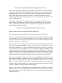
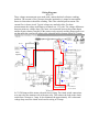
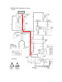
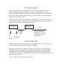
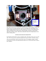
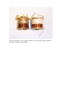
Diagnosing and Understanding Starting Problems on the ZR-1
Marc Haibeck
28-Sep-13
There are three basic failure conditions:
- A VATS security system lockout
- A click from the starter solenoid but no engine cranking
- Silence when the ignition key is rotated into the start position
VATS Security System Lockout
The VATS security system measures the electrical resistance of the ignition key pellet
when the ignition key is turned to the on position. If the expected resistance is not
detected, the system will prevent the start relay from activating. It will also prevent the
fuel injectors from activating. When a VATS lockout is in progress the Security lamp
will be lit in the gauge cluster while the ignition key is held in the cranking position and
the starter is not activating. Once a lockout is initiated, the system will prevent operation
of the start relay for 10 minutes. A lockout can be caused by a poor electrical connection
between the key and the lock contacts or by a broken lock contact wire in the steering
column. The fuel pump prime cycle will still occur during a VATS lockout.
The CCM body control system and the ECM record evidence of a VATS lockout. The
CCM collects the best information. Error codes 51 through 63 provide detailed
information as to why the VATS event occurred. The ECM will record error code 46 if it
was instructed by the VATS system to lockout the fuel injectors. To access the codes,
connect two pins in the ALDL connector under the dash together. To view CCM errors
on ’90 to ‘93 cars, connect pins A and G. On ’94 and ’95 cars, connect pins 4 and 12. If
errors have been recorded, the speedometer display will show them in the 1.0 mode.
Refer to the service manual section 8D for detailed information. To view an ECM error
on ’90 to ’93 cars connect ALDL connector pins A and B. On ’94 and ’95 cars connect
pins 4 and 5. The check engine lamp will blink the error code.
When a VATS lockout occurs, the car can’t be push started because the fuel injectors are
disabled. If further attempts are made to start the car while the 10 minute VATS lockout
period is in progress the lockout period will be extended.
The VATS system starter lockout can be disabled by removing the start relay and placing
a spade pin jumper in relay socket pins 30 and 87. The fuel lockout can be disabled with
a data bit modification in the engine control system calibration chip.
A VATS lockout can be caused by moving the ignition key too fast. This should not
occur, but if it does the simple solution is to slowly turn the key to on, hesitate a moment
and then slowly proceed to the crank position. Turning the key to start too quickly can
cause the key resistor pellet to be misread.
The Starter Solenoid Clicks But the Engine Does Not Crank
The sound of the starter solenoid click is muffled because the starter is located inside the
valley of the engine. If the solenoid clicks but the engine does not crank, the solenoid is
activating but there is one of two faults in the starter. The solenoid motor contacts may
not be connecting the starter motor to the battery. Or, the starter brushes may not be
contacting the starter armature because they are worn. The starter must be replaced if one
of these conditions exists.
In this starter failure mode, the car will push start. Use first gear with an OE 3.45 rear
axle gear ratio. Use second gear with a 4.10 rear axle ratio. If the car can’t be pushed,
there is a small chance that starter may be vibrated to life by tapping the starter with a
pipe while the solenoid is activated.
The Starter is Silent When the Key is Turned to Start
Make sure the floor mat is not folded under the clutch pedal.
This situation requires electrical analysis because there is a long list of suspects.
The battery voltage should be at least 12 volts at the battery terminals when the ignition
key is turned to start. The battery terminals need to be tight. If present, a battery
disconnect switch can develop a poor connection. It may run the interior lights but may
not deliver enough current to the starter.
Remove the driver’s side hush panel from under the dash. Find the black clutch switch
connector. It has purple and yellow 10 gauge wires on one side. The purple wire is red on
the first three hundred or so ’90 cars. Measure the voltage on the purple wire when the
key is turned to start. It is normally 10 to 11 volts when the engine is cranking. If the
voltage is less than one volt there is an open in the starter solenoid circuit. The starter
solenoid could be open. The clutch pedal switch could be open. The start relay could be
open. If the voltage is more than one and less than 10 volts there is too much electrical
resistance in the circuit. Measure the voltage drops across the three items listed above.
Measure the current on the purple wire. The current is normally 28 to 30 amps when the
starter solenoid initially is connected. This is the solenoid pull-in coil current. The current
drops to nine to 10 amps when the starter is cranking the engine. This is the solenoid
hold-in coil current. If the current is 28 to 30 amps and the starter is silent, the starter
solenoid is ether stuck physically or the solenoid coil has shorted turns and can’t develop
enough of a magnetic field to pull the solenoid plunger in.
If there is an excessive voltage drop in the solenoid circuit, and there is a solenoid
plunger or solenoid coil related problem, the problem will be worse when the engine is
hot because the heat increases the voltage drop in the wiring and thus reduces the current
to the solenoid coil.
Wiring Diagrams
‘90 to ‘92
These voltage measurements were made with a starter that had a silent no cranking
problem. The current is 28 to 30 amps when the ignition key is turned to start and the
starter is silent when it should be cranking. This is the solenoid pull-in current. The
current flow is shown in red. Typical voltages are marked in blue. For these
measurements the voltage at the battery terminals was 12.2 volts. The voltage differences
between points are voltage drops. The meter was connected between the points shown
and the negative battery terminal. If the starter works correctly and the plunger pulls in to
run the motor the current will reduce to the solenoid hold-in current of nine to 10 amps.
12.2 v
11.7 v
11.3 v
Meter
negative.
11.2 v
11.1 v
From the GM
service manual.
’93 to ‘95
In ’93 GM improved the starter solenoid circuit wiring. The clutch switch connections
were moved to the armature side of the start relay. This reduces the load on the clutch
switch from 30 amps to .2 amp. It also eliminates the approximately .050 volt normal
voltage drop across the clutch switch and its wiring at 30 amps.
From the GM
Service manual.
The 24 Volt Wakeup Call
I have been able to revive two silent starters. One was on a car that was stored in a
climate controlled room and not started for 10 years. Another was on a car that was
stored in a cold garage and not started over a Chicago winter. Both cars continued on for
many years without a further starter problem. I suspect that these cars had high plunger
friction after the storage periods.
The plunger pull-in force can be doubled by applying 24 volts. Place a second battery in
series with the car battery. Apply the 24 volts to the purple wire. Apply the current for
one half second to prevent overheating the solenoid.
Car Bat.
Neg
Boost Bat
Pos
Neg
24 volts.
Pos
12 gage wire to the
purple wire. The wire
should be less than 25
inches long.
Jumper
Cable
To
Car
Chassis
To Car
Electronics
Starter Installation Tips
Bend the purple solenoid wire so that when it is plugged in, there is tension on it. This
will minimize fretting on the terminal pin due to vibration.
The battery terminal stud is sensitive to rotation. If it is rotated, the contact inside the
solenoid will twist out of alignment. This can result in the plunger contactor making a
connection on the corner of the contact rather than across the face. This can greatly
shorten the life of the contact. Hold the battery cable stationary when tightening the nut to
prevent rotation of the stud.
This is a picture of a solenoid with new contacts.
Don’t let the
battery cable stud
rotate when
tightening the
cable.
The contacts need to be level and square with the housing so that the plunger contact disk
will lie evenly across them and make contact across the full faces of the contacts. The
battery terminal stud does not have an anti-rotation stop. If it moves when tightening the
cable it will lift the corner of the contact. Then the plunger will make a point contact
rather than a full-face contact. This leads to shortened contact life and potentially a click
and no cranking failure.
An Observation About the Solenoid Coil
OE solenoid coils that I have seen are wound unevenly. The turns of wire cross over each
other. This creates pressure points that might break down the shellac insulation coating
on the wires and lead to a short circuit between turns. The insulating coating is further
stressed by the oven like environment that the starter lives in. This could cause a silent no
start condition.
The coil on the right is a new replacement part coil. It is smoothly wound. Maybe the
smoothly wound coil is more durable.