1
AF-08CRL
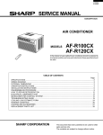
SERVICE MANUAL
S3211AF08CRL/
AIR CONDITIONER
MODEL
AF-08CRL
In the interests of user-safety (Required by safety regulations in some
countries) the set should be restored to its original condition and only
parts identical to those specified should be used.
TABLE OF CONTENTS
Page
SPECIFICATIONS ................................................................................................................................................ 2
WIRING DIAGRAM ............................................................................................................................................... 3
EXTERNAL DIMENSIONS ................................................................................................................................... 4
HOW TO OPERATE ............................................................................................................................................. 5
INSTALLATIOIN INSTRUCTIONS ...................................................................................................................... 13
DISASSEMBLING PROCEDURE ....................................................................................................................... 16
HOW TO REPAIR REFRIGERATION ................................................................................................................. 19
ELECTRICAL COMPONENT TEST .................................................................................................................... 21
MICROCOMPUTER CONTROL SYSTEM .......................................................................................................... 22
TROUBLESHOOTING GUIDE ............................................................................................................................ 26
COOLING LOAD ESTIMATE FORM ................................................................................................................... 31
RUNNING CONDITION ....................................................................................................................................... 33
PACKING AND ACCESSORIES ......................................................................................................................... 34
REPLACEMENT PARTS LIST ............................................................................................................................ 35
SHARP CORPORATION
This document has been published to be used for after
sales service only.
The contents are subject to change without notice.
1
AF-08CRL
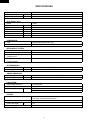
SPECIFICATIONS
Models
Cooling capacity
Moisture removal
ELECTRICAL DATA
Phase
Rared frequency
Rated voltage
Rated current
Rated input
Power factor
EER
BTU/h
Pints/h
AF-08CRL
8000
2.3
Hz
Volts
Amps
Watts
%
BTU/Wh
Single
60
115
7.3
800
95
10.0
COMPRESSOR
Type
Model, Motor output
(Hermetically sealed rotary type)
2R12S3R126A-6A, 600W
REFRIGERANT SYSTEM
Evaporator
Condenser
Control O.D. x I.D. x Length x Q'ty(mm)
(Capillary tube)
Refrigerant volume R-22(OZ)
(Factory change)
Louver fin, Grooved tube, 7mm, Hair pin
Louver fin, Grooved tube, 7mm, Hair pin
2.7 x 1.2 x 450 x 1
15.9
NET DIMENSIONS
Width Height Depth
Net Weight
inches(mm)
lbs
19-11/16(500) x 14-9/16(370) x 17-3/32(434)
53
GROSS DIMENSIONS
Width Height Depth
Gross Weight
inches(mm)
lbs
22-27/32(580) x 18-5/16(465) x 19-31/32(507)
60
FAN SYSTEM
Indoor side(Evaporator)
Outdoor side(Condenser)
Air flow rate(indoor side) CFM
OTHERS
Safety devices
Air filter
Power cord length
Power plug type
ft
Centrifugal fan
Propeller fan
High / Med / Low
187 / 173 / 155
Compressor: Overload relay
Fan motor: Internal thermal protector
Polypropylene net
6.0
125V, 10A
2
AF-08CRL
ELECTRICAL PARTS
Models
Running capacitor
Fan capacitor
Thermistor
Fan motor
Overload relay
AF-08CRL
250V-35µF
250V-6µF
15kΩ at 78˚F
OBM-2508K1 (MLB003)
MRA98706
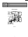
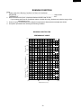
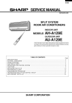
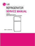
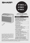
WIRING DIAGRAM
POWER SUPPLY CORD
115V 60Hz
NON RIBBED
IN
GR
OUT
MRY
BK
COMPRESSOR C
MOTOR
RIBBED
RUNNING R
CAPACITOR
250V 35µF RE
FU1
CONTROL
BOARD UNIT
NR
OVERLOAD
PROTECTOR
FAN MOTOR
CAPACITOR
250V 6µF
BL
BK
BK
S
BL
M.C
WH
EARTH
GR
Figure W-1
3
THERMISTOR
(ROOM TEMP)
YELLOW
CNR2 BCN2
GY
RE
OR
WH
A.C
CN1
CNR1
GY
THERMAL
PROTECTOR
C1
TR
8
7
1
3
5
1 2 3 6 5 4 CONNECTOR BCN1
BL BK GY RE OR WH
H M L
FAN MOTOR
BK
WIRE COLOR
BK : BLACK
BL : BLUE
RE : RED
WH : WHITE
GR : GREEN
GY : GRAY
OR : ORANGE
3A 125V
CNR3
RY1
RY2
RY3
TH1
CN2
DISPLAY
BOARD
UNIT
BCN3
CN3
AF-08CRL
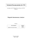
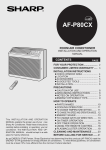
EXTERNAL DIMENSIONS
19-11/16"
4-15/32"
Fig. E-1.
4
15-11/16"
23-5/8" (full closed)
13-5/8"
5
1-15/32"
17-3/32"
35-7/16" (full opened)
AF-08CRL
HOW TO OPERATE
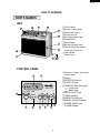
PARTS NAMES
UNIT
5
4
3
6
7
8
9
10
2
1
1Front Cabinet
2Air Inlet (Indoor Side)
3Horizontal Louvers
4Vertical Louvers
5Air Outlet (Indoor Side)
6Control Panel
7Rear Cabinet
8Air Inlet (Outdoor side)
9Filter (Pull the filter handle
to the right to remove.)
0Filter Handle
qPower Cord
11
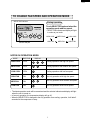
CONTROL PANEL
2
1
F
hr
COOL / FAN
TEMP
3
ENERGY
SAVER
TIMER
SELECTOR
ON/OFF
7
4
5
6
POWER
ON/OFF
11
9
8
10
5
1Receiver window for remote
control signal
2Display
3SELECTOR indicator
4SELECTOR pad
5TEMPERATURE setting pad
----Lower temp.
----Raise temp.
6TIMER ON/OFF pad
7TIMER indicator
8ENERGY SAVER pad
9ENERGY SAVER indicator
0POWER ON/OFF pad
qPOWER indicator
AF-08CRL
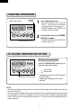
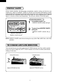
COOLING OPERATION
POWER
indicator
SELECTOR indicator
1
Touch POWER ON/OFF pad.
• The unit is preset at 74°F and HIGH
COOL. This will show in the display
when the power is first turned on.
• POWER indicator and SELECTOR
indicator (COOL) will light.
F
hr
COOL / FAN
TEMP
TIMER
SELECTOR
ON/OFF
ENERGY
SAVER
POWER
ON/OFF
2
To turn off the unit, touch POWER
ON/OFF pad again.
• POWER indicator and SELECTOR
indicator will go off.
POWER ON/OFF pad
TO CHANGE TEMPERATURE SETTING
During cooling operation
F
Touch the TEMPERATURE setting pad to
adjust the temperature setting.
hr
COOL / FAN
SELECTOR
TEMP
TIMER
ON/OFF
ENERGY
SAVER
---Lower
temp.
---Raise temp.
POWER
ON/OFF
TEMPERATURE setting pad
• Temperature can be set within the range
of 64°F to 86°F.
• Display will change as you touch
the pad.
NOTE:
• The latest temperature setting will be memorized and will appear on the display the next time
the unit is turned on.
• In cases of power outages or when the unit is disconnected; when the power is restored or the
unit is plugged in, the unit and display will return to the preset conditions of 74°F and HIGH
COOL. The unit will not automatically turn back on. The user must touch POWER ON/OFF to
resume opertion.
6
AF-08CRL
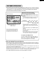
TO CHANGE FAN SPEED AND OPERATION MODE
SELECTOR indicator
During operation
Touch SELECTOR pad and select the
operation mode and fan speed.
F
hr
COOL / FAN
• SELECTOR indicator and display will light
in order as you touch.
TEMP
TIMER
SELECTOR
ON/OFF
ENERGY
SAVER
POWER
ON/OFF
SELECTOR pad
HIGH COOL
MED COOL
LOW COOL
LOW FAN
MED FAN
HIGH FAN
NOTES ON OPERATION MODE:
MODE
SELECTOR
DISPLAY
HIGH COOL
COOL
Cooling operation with high fan speed.
MED COOL
COOL
Cooling operation with medium fan speed.
LOW COOL
COOL
Cooling operation with low fan speed.
HIGH FAN
FAN
Fan only operation with high fan speed.
MED FAN
FAN
Fan only operation with medium fan speed.
LOW FAN
FAN
Fan only operation with low fan speed.
• The latest operation mode will be memorized and the selector indicator and display will light
when the unit is turned on.
• In fan only operation, the temperature display will go off.
• When the SELECTOR is changed to fan only operation from cooling operation, it will take 5
seconds for the compressor to stop.
7
AF-08CRL
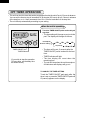
ENERGY SAVER
During normal operation, the thermostat automatically controls cooling and the fan runs
continuously. When the ENERGY SAVER is selected, the thermostat automatically controls
cooling and the fan automatically stops when the compressor is not operating. (Fan will stop 30
seconds after the compressor stops. After the fan stops, the fan is programmed to rotate for
approx. 2 minutes to detect room temperature. This will occur within a 20 min time span.)
During cooling operation
F
1
Touch ENERGY SAVER pad.
2
To cancel, touch ENERGY SAVER
pad again.
• ENERGY SAVER indicator will light.
hr
COOL / FAN
SELECTOR
TEMP
TIMER
ON/OFF
ENERGY
SAVER
POWER
ON/OFF
• ENERGY SAVER indicator will go
off.
ENERGY SAVER pad
ENERGY SAVER indicator
NOTE: ENERGY SAVER cannot be set during fan only (HIGH FAN, MED FAN, LOW FAN)
operation.
TO CHANGE AIR FLOW DIRECTION
The horizontal louvers are used to adjust the UP / DOWN direction of air flow, and the vertical
louvers are used to adjust the LEFT / RIGHT direction of air flow for uniform and efficient
cooling of the room.
Horizontal louvers
Vertical louvers
Lever
Adjust UP/DOWN air flow
Adjust LEFT/RIGHT air flow
8
AF-08CRL
ON TIMER OPERATION
• This unit has a built-in timer that can be programmed to start the unit up to 12 hours in advance.
You can set the timer to start in increments of 30 minutes (0.5 hours) up to 9.5 hours in advance
of the start time, or in 1 hour increments from 10 to 12 hours in advance of the start time.
• The unit will start automatically according to your setting.
When the unit is not operating
SELECTOR indicator
1
F
• The time setting will change as you touch the
pad. The display will change as follows;
hr
COOL / FAN
SELECTOR
Touch the TIMER ON/OFF pad to set the delayed
start time.
TEMP
TIMER
ON/OFF
ENERGY
SAVER
POWER
ON/OFF
Preset(0.5h)
Previous setting
0.5h
1.0h
CL(cancel)
TIMER ON/OFF pad
TIMER indicator
(If you wish to start the operation
6 hours and 30 minutes later, set
the delay time as shown above.)
1.5h
12h
10h
11h
• The timer will be set, 5 seconds after the
TIMER ON/OFF pad is touched for the last
time.
• SELECTOR indicator and TIMER indicator
will light.
• The time display will count down the
remaining time.
• The unit will start when the set time expires.
The temperature setting will be displayed.
TO CANCEL THE TIMER SETTING
Touch the TIMER ON/OFF pad again after the
timer is set, or press the TIMER ON/OFF pad
until CL(cancel) appears on the display.
NOTES FOR TIMER SETTING AND OPERATION:
• After setting the TIMER, change the temperature and fan speed settings as shown on pages 11
and 12. When the temperature is set in the timer mode, the temperature will show in the display
for 5 seconds and then return to the time display.
• The last setting used will be memorized and will appear on the display the next time you
operate the unit with the TIMER function.
• If a power failure occurs while the ON or OFF TIMER is set, the TIMER memory will be cancelled
and will not resume even after power is reinstated. The unit will not automatically start.
• OFF TIMER OPERATION can also be set with the REMOTE CONTROL.
9
AF-08CRL
OFF TIMER OPERATION
• This unit has a built-in timer that can be programmed to shut the unit off up to 12 hours in advance.
You can set the timer to stop in increments of 30 minutes (0.5 hours) up to 9.5 hours in advance
of the stop time, or in 1 hour increments from 10 to 12 hours in advance of the stop time.
• The unit will stop automatically according to your setting.
When the unit is operating
1
F
• The time setting will change as you touch the
pad. The display will change as follows;
hr
COOL / FAN
SELECTOR
Touch the TIMER ON/OFF pad to set the delayed
stop time.
TEMP
TIMER
ON/OFF
ENERGY
SAVER
POWER
ON/OFF
Preset(0.5h)
Previous setting
0.5h
1.0h
CL(cancel)
TIMER ON/OFF pad
TIMER indicator
(If you wish to stop the operation
10 hours later, set the delay time
as shown above.)
1.5h
12h
10h
11h
• The timer will be set, 5 seconds after the
TIMER ON/OFF pad is touched for the last
time.
• TIMER indicator will light.
• The time display will count down the
remaining time.
• The unit will stop when the set time expires.
All indicators and displays will go out.
TO CANCEL THE TIMER SETTING
Touch the TIMER ON/OFF pad again after the
timer is set or, press the TIMER ON/OFF pad until
CL(cancel) appears on the display.
10
AF-08CRL
USING THE REMOTE CONTROL
INSTALLING BATTERIES
Use two size-AAA (R03) batteries.
1
2
Remove the battery compartment cover.
3
Replace the cover.
Insert the batteries in the compartment,
making sure the
and
polarities
are properly aligned.
Battery compartment cover
NOTES:
• The battery life is approximately one year with normal use.
• When you replace the batteries, always use two new ones of the same type.
• If the remote control does not operate normally after replacing the batteries, take out the
batteries and replace them again after 30 seconds.
• If you will not be using the unit for a long time, remove the batteries from the remote control.
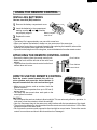
ATTACHING THE REMOTE CONTROL HOOK
• Remove the backing from the remote control hook.
• Attach the hook onto the left side of the unit's front
cabinet.
• To prevent loss, hook the remote control on the front
cabinet when not in use.
Rear Cabinet
Front Cabinet
Remote control hook
HOW TO USE THE REMOTE CONTROL
Point the remote control towards the unit's receiver window and press the desired button. A
beep will sound when the unit receives the signal.
• Make sure no objects, such as curtains, block the
receiver window.
• The remote control operates from up to 20 feet (6
meters) away.
• The beep will also sound when each pad on the
control panel is touched.
CAUTION:
• Do not expose the receiver window to direct sunlight. This can adversely affect its operation. In
such case, close the curtains to block the sunlight.
• Use of a fluorescent lamp in the same room may interfere with the transmission of the signal.
• The unit may be affected by signals emitted from the remote control of a television, VCR or other
equipment used in the same room.
• Do not leave the remote control exposed to direct sunlight or near a heater. Protect the remote
control from moisture and shock which can discolor or damage it.
11
AF-08CRL
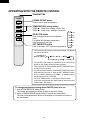
OPERATING WITH THE REMOTE CONTROL
TRANSMITTER
POWER
ON/OFF
POWER ON/OFF button
Push to start or stop the operation.
TEMP.
TEMPERATURE setting button
TEMP.
TEMP.
TEMP.
---Raise
---Lower
temp. setting 1°F at a time.
temp. setting 1°F at a time.
SELECTOR
HIGH COOL
SELECTOR button
SET TIMER/OFF
MED COOL
Push to change fan speed and operation
mode.
Fan speed and operation mode selections are shown to the right.
LOW COOL
HIGH FAN
MED FAN
SET TIMER/OFF button
LOW FAN
Push to set delay "OFF" timer during operation.
• The time setting will change as you push the button. The display
will change as follows;
Preset(0.5h)
Previous setting
0.5h
1.0h
CL(cancel)
1.5h
12h
10h
11h
• The last OFF time setting is memorized by the unit and will
appear on the display when the button is pushed.
• The timer will be set, 5 seconds after the SET TIMER/OFF button
is pushed for the last time.
• If you wish to cancel the timer, push the SET TIMER/OFF button
again after the time is set or, push the SET TIMER/OFF button
until CL (cancel) appears on the display. A double beep will
sound when the timer is cancelled.
• The "ON" TIMER cannot be set with the remote control.
It can only be activated by the TIMER ON/OFF pad on the unit's
control panel ( See page 9 ).
To change temperature setting when ON/OFF timer is in use
1. Push a TEMPERATURE setting button.
The current set temperature will be recalled on the unit's display.
2. Use the TEMPERATURE setting buttons to set the new temperature.
The new set temperature will show on the display for 5 seconds and return to
the time display.
12
AF-08CRL
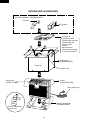
INSTALLATION INSTRUCTIONS
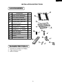
ACCESSORIES
1
No.
Accessories
Q'ty
1
Right closure assembly
1
2
Left closure assembly
1
3
Window sash foam seal
1
4
Window sash foam seal
(adhesive type)
1
5
Bottom gasket
1
6
Screws (L=1", 25.4mm)
7
13
7
Screws (L= /32", 10mm)
6
8
Base pan angle
2
9
Remote control
1
10
Battery
2
11
Remote control hook
1
2
3
4
5
6
7
6
7
8
2
9
11
10
2
SUGGESTED TOOLS
1. Screw driver (medium size Phillips)
2. Tape measure or ruler
3. Knife or scissors
13
AF-08CRL
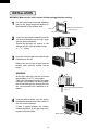
INSTALLATION
WARNING: Make sure the unit is turned off and unplugged before working.
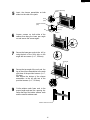
1
Sash
Cut the window sash foam seal (adhesive
type) to the proper length and attach it to
the underside of the window sash.
Window sash foam seal
(adhesive type)
Jamb
Sill
2
3
Insert the right closure assembly and the
left closure assembly into the top angle
and the bottom channels.
Secure the right and left closure to the
cabinet with six of the provided screws.
(L= 13/32", 10mm)
Closure assembly
Open the window sash and place the air
conditioner on the sill.
Balance the unit on the sill and close the
window sash securely behind the top
angle.
WARNING:
unit
At this step, make sure the unit is inclined
approximately 1 cm (3/8") to the back.
If the unit is not properly inclined, the water
collected in the bottom tray during operation will not drain properly and may flow into
the room where the air conditioner is installed.
4
sill
Insert the bottom gasket into the space
between the window sill and the bottom of
the unit to seal outside air.
If there is space between the bottom
channel and the sill, fill the gap with a thin
board or other hard filler.
Bottom gasket
14
incline backwards approximately
1cm (3/8")
AF-08CRL
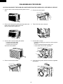
5
Closure assembly
(Left)
Insert the closure assemblies on both
sides into the rails of the jamb.
Jamb
(Left)
Indoor
side
Closure assembly
(Left)
Indoor
side
1/2 inches
(13mm)
Sill
Stool
6
Loosen screws on both sides of the
cabinet, then hang the base pan angle
on and secure the screws again.
7
Secure the base pan angle to the sill by
using the hole of the front side on the
angle with one screw. (L=1", 25.4mm)
Top angle
8
Secure the top angle of the unit and the
top of the closure assemblies to the sash
with three of the provided screws. (L=1",
25.4mm)
And secure the bottom of the closure
assemblies to the sill with two of the
provided screws. (L=1", 25.4mm)
9
Cut the window sash foam seal to the
proper length and seal the opening between the top of the inside window sash
and the outside window sash.
Window sash foam seal
15
AF-08CRL
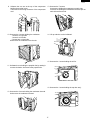
DISASSEMBLING PROCEDURE
CAUTION: DISCONNECT THE ROOM AIR CONDITIONER FROM THE POWER SUPPLY BEFORE ANY SERVICE
1. Unscrew the 2 screws holding the front panel on each
side.
5. Remove the control panel.
2. Remove the front panel by pulling the front panel at the
lower corner toward you about one inch.
Next lift up and pull it toward you.
6. Take off the fan motor connector.
3. Unscrew the 8 screws holding the cabinet.
2 screws are on each side.
4 screws are on back side.
2 screws are on top side.
And remove the cabinet.
7. Unscrew the 5 screws.
3 screws are holding the control box at the top and
right side.
1 screw is holding the power supply cord.
1 screw each screw on the evaporator.
4. Remove the thermistor holder.
8. Cut the wire fixing band, slide the control box rightward
and remove.
Slide
16
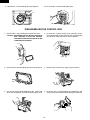
AF-08CRL
9. Unfasten the one nut at the top of the compressor
holding the terminal cover.
Then remove the wiring connector of the compressor
cord.
13. Unscrew the 7 screws.
4 screws are holding the evaporator on each side.
3 screws are holding the bulkhead to the base pan on
each side and back side.
10. Unscrew the 4 screws holding the condenser.
1 screw is on right side.
1 screw is on left side.
2 screws are on back side.
And remove the condenser from the unit.
14. Lift up and take out the bulkhead.
15. Unscrew the 1 screw holding the orifice.
11. Unfasten the nut holding the propeller fan by rotating it
counter-clockwise. And remove the propeller fan.
16. Unscrew the 1 screw holding the top duct ass'y.
12. Unscrew the 2 screws holding the condenser shround.
And remove the condenser shround.
17
AF-08CRL
17. Unscrew the 1 screw holding the centrifugal fan.
18. Unscrew the 3 screws holding fan motor.
DISASSEMBLING THE CONTROL BOX
1. Unscrew the 1 screw holding the control box cover.
CAUTION: DISCHARGE THE FAN MOTOR CAPACITOR
AND RUNNING CAPACITOR BEFORE
TOUCHING THOSE CAPACITORS OR OTHER
COMPONENTS OR WIRING.
4. Unscrew the 1 power supply cord grounding screw.
Unscrew the earth screw. Unscrew the 1 screw holding
the capacitor clamp and the fan motor capacitor.
2. Unscrew the 3 screws holding the printed wiring board.
5. Detach each connector by using long-noise pliers.
3. Cut the wire fixing bands holding the fan motor lead
wires, the compressor cord and the power supply cord.
6. Unscrews the 2 screws holding the transformer and
remove the control board with unhooking the 2 spacers.
18
AF-08CRL
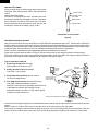
HOW TO REPAIR REFRIGERATION
Before sealed system work can be preformed a refrigerant recovery EPA and LOCALLY approved certification is
required, additionally, EPA and LOCALLY approved refrigerant recovery equipment is required.
SEALED SYSTEM REPAIR
Sealed system repairs should be properly diagnosed before entering into a repair of the system.
It is important to follow proper procedures when doing a system repair for safety reasons and that the repair will result in a
restoration of the system to proper factory standards.
SAFETY REMINDERS
1) Do not heat any system component with an open flame for any reason.
2) Do not solder until you are sure that all refrigerant has been removed from the system.
3) Do not heat the charging cylinder with an open flame. Use warm water only and do not exceed 125˚F(not too hot to keep
your hand in.)
4) Do not over fill any charging cylinders, as they could explode when over
filled.
GOOD FIT
5) Use proper wrenches.
6) Use safety goggles when working with refrigerants.
PROPER
7) Keep a fire extinguisher within easy reach.
JOINT FIT
CLEARANCE
8) Watch flame direction when soldering so as not to burn clothing, wiring or
0.01" TO 0.03"
other components.
9) Solder in a well ventilated area. If a high concentration of freon is present,
an open flame will create phosgene gas which can be harmful.
PROPER SOLDERING
POOR FIT
Joint clearances should be maintained so that the brazing alloy will flow
between the closely mated surfaces rather than forming large fillets.
This films make the strongest joints, capillary attraction also work best with
close tolerance.
The best clearance is between 0.01" to 0.03" , the amount of lap will be
approximately 3/8" depending on the swaging tool used. (Figure 1.)
Joint Clearance.
Figure 1
EMERY CLOTH
CLEANING TUBING
To make a sound, leak tight joint, the brazing alloy when raised to brazing
temperature, must wet and flow freely over the entire surface of the tubing in
the joint area.
To assure this, the tubing surfaces must be free of all dirt, grease, oil and
oxides otherwise the alloy will not wet and flow properly over any surface with
these elements present. Cleaning can be done with an abrasive cloth or steel
wool. Never blow into the tubing because this will introduce a lot of moisture
into the system. Open tubing joints should be covered if exposed for long
periods of time.
KEEP TUBE IN
DOWNWARD POSITION
Cleaning Tubing.
Figure 2
PROPER FLUXING
3/8"
Flux is necessary when using silver solder; it is not required
when using silfos on copper to copper joints.
To do a good job the flux should cover the tube surface
completely. Be careful not to introduce any flux inside the
tubing.
Fluxing should be done after the tubing is mated together
and just before brazing is done. Do not allow it to dry out.
When brazing, the flux should become entirely liquid and
clear, like water. The temperature will be at 1100˚F and only
a little more heat will allow the alloy to flow freely into the joint.
SILVER ALLOY
INNER CONE
TORCH STEM
Directing Torch Flame to Copper Tubing.
Figure 3
19
AF-08CRL
HEATING THE TUBING
Direct the torch flame so that the larger tube receives most
of the heat. Silver solder flows at 1200˚F and silfos flows at
1300˚F.
Heat all around the tubing.
The flame is composed of two cones, a smaller inner cone
(pale blue) in calor and a much larger outer cone. The hottest
part of the flame is at the tip of the inner cone. The flame
should be directed at the joint with the tip of the cone just
touching the surface of the tubing. Figure 3 and 4.
OUTER CONE
HOTTEST PART
OF FLAME
INNER CONE
TORCH STEM
Composition of Torch Flame.
Figure 4
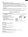
DEHYDRATING SEALED SYSTEM
Many servicers feel that since air conditioners run with evaporator temperatures above 33˚F, moisture will not present a
problem. Nothing is further from the truth. Oxygen in moisture plus the heat produced during compression will react with the
refrigerant oil to produce harmful acids in the system which will break down motor winding insulation, create sludge and pit
component parts, reducing efficiency of the air conditioner and shortening the life of compressors.
There it becomes mandatory that good dehydrating practices be adhered to at all times.
Proper hook up procedures as shown in Figure 5 must be used in order to pull and good vacuum from the system.
The use of a good vacuum pump is very important so that the boiling point of any water in the system will be lowered to a
point where it will vaporize and be expelled from the system in the form of vapour.
Type of evacuation methods
1. Piston Type Compressor No good.
System parts must be above 110˚F.
2. Rotary Vacuum Pump Disavantages.
Low CFMC. 4 oil gets dirty.
3. Single State Vacuum Pump will not clean oil.
Oil must be changed often.
DIAL-CHARGE
CHARGING CYLINDER
ELECTRIC
VACUUM
GAUGE
LOW SIDE
GAUGE
TO RELATED SERVICE
VALVE OR PROCESS
TUBES OF THE UNIT.
4. Two Stage Vacuum Pump will reach 50 microns.
First stage is below atmospheric pressure.
Moisture is removed into second stage which works up
to atmospheric pressure thus keeping oil clean.
Manometer cannot be read to 1/2 mm. Micron gauge
reads from 25,400 microns to 0.
HIGH SIDE
GAUGE
HIGH VACUUM
MANIFOLD
LARGE DIAMETER
BRAIDED VACUUM
HOSES
Hook up for Evacuation and charging
HIGH VACUUM PUMP
Figure 5
It becomes clear that good equipment and maintained properly must be used in order to remove air and moisture from the
system.
When a vacuum of 1,000 to 500 microns is reached, block off the vacuum pump from the system.
This is done by closing the value between the pump and system. If the micron gauge does not increase above 1,000, the
system is free of moisture and no leak exists. If the micron gauge increases to higher levels moisture or a leak exists.
20
AF-08CRL
LEAKS
Several methods are used to detect leaks in systems.
Electronic Leak Detectors are very sensitive and are able to detect leaks down to 1/2 ounce per year.
A good electronic leak detector is generally far better in locating very small leaks.
Halide Torch be sure the room is free from refrigerant vapours. Watch the flame for the slightest change in calor.
A very faint green indicates a small leak. The flame will be unmistakably changed to green or purple when large leaks
are encountered. To simplify leak detection pressurize the system to approximately 75 lbs.
Some leaks can be located by a visual inspection of the system components and solder joints and if oil is found at any
given location it generally is a sign that a leak exists at that point due to the fact that flame does carry oil with it travels
through the system.
Soap Bubbles
Liquid detergents can sometimes assist in finding small leaks by brushing detergent on the suspect area and
watching for bubbles. Before applying detergent be sure that the system is pressurized.
Tap line devices are permissible for diagnosis only they are not suitable when evacuating the system. After the diagnosis
has been made they must be removed so that the system will be restored to a hermeticly sealed condition.
ELECTRICAL COMPONENT TEST
RUNNING CAPACITOR AND FAN CAPACITOR
CAUTION: DISCHARGE THE RUNNING CAPACITOR AND FAN CAPACITOR BEFORE TOUCHING CAPACITOR
OR WIRING.
(1) Discharge capacitor by shorting terminals.
(2) Take the wires off the capacitor terminals.
(3) Set the selector switch of a volt-ohm-meter (or a tester)
on the resistance range.
(4) Connect the probes to the capacitor terminals and
watch the indicator swing.
The indicator does not swing at all ..... Open.
The indicator swings but does not return ..... Shorted.
The indicator swings, then returns a moment later .....
Good.
FAN CAPACITOR
RUNNING CAPACITOR
INSULATION TEST
Check the resistance between the terminals and case.
Reading must be more than 10MΩ at DC 500V.
OVERLOAD RELAY
Check continuity between terminals with volt-ohm-meter.
INSULATION TEST
Check resistance between terminals and the relay case.
Reading must be more than 10MΩ at DC 500V.
COMPRESSOR
(1) Take the wires off compressor terminals.
(2) Set selector switch of volt-ohm-meter on the resistance range.
(3) Put the probes on the terminals of the compressor and check continuity between each terminal.
INSULATION TEST
Check the resistance between the terminals and the copper tube.
Reading must be more than 10MΩ at DC 500V.
21
AF-08CRL
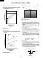
MICROCOMPUTER CONTROL SYSTEM
1. Temperature control characteristic
1-1 COOL operation
In the “COOL” mode, the thermostat circuit is controlled
by two thermostat lines (C1, C2).
3. Fan speed
Fan speeds are given by the fan motor, “H”, “M” and
“L”, which are available in the following operation
mode.
Room temperature (°F)
Table Y-1
86
C1
84
C2
64
Fan motor
H
M
L
H
M
L
4. 12-hours timer
62
64
Preset temperature (°F)
("THERMO" switch)
86
Figure Y-1
2. Operation mode
2-1 COOL operation
The compressor turns on or off, at thermostat lines C1
and C2. The fan motor is also controlled with the
compressor.
States 1 & 3 : Compressor ON
States 2
: Compressor OFF
3
Room temperature (°C)
Selector
HIGH COOL
MED COOL
LOW COOL
HIGH FAN
MED FAN
LOW FAN
C1
4-1 OFF-TIMER operation
Set the delay timer during operation.
The unit will turn off automatically according to your
setting. Timer duration can be set by 0.5 hours to
maximum 12 hours. Up to 9.5 hours, you can set by 0.5
hours increments and from 10 to 12 hours, by 1 hour
increment.
If you touch button “POWER ON/OFF” during OFFTIMER operation, then the unit turns off and OFFTIMER operation is cancelled.
4-2 ON-TIMER operation
Set the delay timer when unit is not operating.
The unit will turn on automatically according to your
setting. Timer duration can be set by 0.5 hours to
maximum 12 hours. Up to 9.5 hours, you can set by
0.5 hours increments and from 10 to 12 hours, by 1
hour increment.
If you touch button “POWER ON/OFF” during ONTIMER operation, then the unit turns on and ON-TIMER
operation is cancelled.
ON-TIME and OFF-TIME display will count down the
remaining time.
1
from 0.5 to 9.5 ..... 0.5 hours
from 10 to 12 ....... 1 hour
C2
2
Room temperature transition
5. Energy saver
During normal operation, the thermostat automatically
controls cooling and the fan runs continuously whenever
the air conditioner is in operation.
When the ENERGY SAVER is set, the thermostat
automatically controls cooling and the fan automatically
stop when compressor is not operating. (Fan will stop
in 30 seconds after the compressor stops.)
ON
Compressor
Preset temperature (°C)
Figure Y-2
OFF
ON
Fan
2-2 FAN ONLY operation
The fan motor always turns on.
OFF
30 seconds
Figure Y-3
22
AF-08CRL
6. Safety start
When you turn the air conditioner OFF and restart again soon, wait at least 3 minutes before the cooling operation
starts.
7. Test mode
Keep pushing both buttons “POWER ON/OFF” and “ " ” and supply the power, the system will go to the test mode.
In this mode, the output operation is switched by pushing buttons. Normal outputs are shown in Table Y-2.
Table Y-2
For selfdiagnosis check mode
No. PUSH KEY (SWITCH)
0 PLUG IN the power supply cord
while pushing power ON/OFF
key and (down) key.
BEPP LED1
SOUND
LED LIGHTING
COOL
FAN TIMER ENERGY POWER FAN
FAN
FAN
FAN
COMP
HIGH
MID
LOW <LED9> <LED5> <LED7> SAVER ON/OFF OUTPUT OUTPUT
<LED2> <LED3> <LED4>
<LED8> <LED6>
CHECK ITEM
and REMARK
2
8.8
ON
ON
ON
ON
ON
ON
ON
ON
OFF
OFF
LED ALL ON
OFF
LOW
OFF
LED ALL OFF
1
SELECTOR <SW3>
1
OFF
OFF
OFF
OFF
OFF
OFF
OFF
OFF
2
<SW6>
1
01
OFF
2)
OFF
3)
OFF
4)
OFF
OFF
OFF
OFF
3
<SW5>
1
02
ON
OFF
OFF
ON
OFF
OFF
ON
OFF
HIGH O F F
4
TIMER <SW2>
1
03
OFF
ON
OFF
OFF
ON
OFF
OFF
ON
OFF
OFF
5
ENERGY SAVER <SW1>
1
04
OFF
OFF
ON
OFF
OFF
ON
OFF
OFF
LOW
OFF
6
ON/OFF <SW4>
1
05
ON
OFF
OFF
ON
OFF
OFF
ON
OFF
HIGH
ON
1
05
OFF
OFF
OFF
OFF
OFF
OFF
OFF
OFF MIDDLE O F F REMOTE CONTROL CHECK
OFF
OFF
OFF
OFF
OFF
OFF
OFF
OFF
OFF
7 POWER ON/OFF by REMOTE CONTROL
POWER SUPPLY OFF
8
1)
2)
2)
2)
1) MIDDLE O F F
OFF
FAN CHECK
COMPRESSOR CHECK
OFF
If thermistor is normal (nether short nor open), LED is ON.
When A/D (R42) bit 7 = 1, LED is ON.
When A/D (R42) bit 6 = 1, LED is ON.
When A/D (R42) bit 5 = 1, LED is ON.
Table Y-3
T(˚C)
0
1
2
3
4
5
6
7
8
9
10
11
12
13
14
15
16
17
18
19
20
T(˚F)
32.0
33.8
35.6
37.4
39.2
41.0
42.8
44.6
46.4
48.2
50.0
51.8
53.6
55.4
57.2
59.0
60.8
62.8
64.4
66.2
68.0
R(kΩ)
49.33
46.86
44.53
42.33
40.25
38.29
36.44
34.68
33.02
31.45
29.96
28.55
27.22
25.96
24.76
23.62
22.56
21.52
20.55
19.63
18.76
T(˚C)
21
22
23
24
25
26
27
28
29
30
31
32
33
34
35
36
37
38
39
40
V(volts)
1.17
1.21
1.26
1.31
1.36
1.41
1.46
1.51
1.56
1.61
1.67
1.72
1.78
1.83
1.89
1.94
2.00
2.05
2.11
2.17
2.22
V ....... Input the voltage of microcomputer (No. 10-port).
23
T(˚F)
69.8
71.6
73.4
75.2
77.0
78.8
80.6
82.4
84.2
86.0
87.8
89.6
91.4
93.2
95.0
96.8
98.6
100.4
102.2
104.0
R(kΩ)
17.93
17.14
16.39
15.68
15.00
14.36
13.74
13.16
12.60
12.07
11.57
11.09
10.63
10.19
9.78
9.38
9.00
8.64
8.30
7.97
V(volts)
2.28
2.33
2.39
2.44
2.50
2.55
2.61
2.66
2.71
2.77
2.82
2.87
2.93
2.98
3.03
3.08
3.13
3.17
3.22
3.27
BK
BL
GY
BK
M
MRY
CONNECTOR
WHITE
ORANGE
RED
FAN
MOTOR
BL
A
H M L
C
S
5
3
1
6
7
RY1
CNR1
RY2
CNR2
RY3
CNR3
3A
125V
YELLOW
C23, R9
NO INSERT PART
TH1 (15k)
ROOM
Temp
CNR1 - CNR3
BCN1
RUNNING
CAPACITOR
GRAY 250V 35µF
R
COMPRESSOR
MOTOR
4
3
2
1
CN1
12V
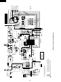
IF NOT SPECIFIED 1SS133T-72 (DIODE)
IF NOT SPECIFIED 50V 1000pF (CAPACITOR)
: INDICATED POSITION IS FUNCTION TEST POINT
RY3
RY2
RY1
MRY
250V
0.1µF
C1
R9
D8
C14
16V
10µ
+
D7 D6
D5
R1
22K
D3
D1
SW1: ENERGY SAVER
SW2: TIMER
SW3: SELECTOR
SW4: POWER
SW5: UP-KEY
SW6: DOWN-KEY
TEST
FAN L
FAN M
FAN H
COMP
NR
271
IF NOT SPECIFIED 1/5W, ±5% (RESISTOR)
CA1: 1000pF x 8 (CAPACITOR ARRAY)
RA1: 10kΩ x 8 (RESISTOR ARRAY)
BL
1 2 3 6 5 4
RE
OVERLOARD
PROTECTOR
GRAY
WH
OR
R22
R10
15K(F)
C3
5V
+
10V
C6
CA1: 1000pF x 8
RA1: 10kΩ x 8
5V
C12
25V
0.1µ
5V
RA1
C22
C21
+
5V
25V
0.1µ
C7
C11
16V
10µ
C20
COM
100µ
OUT
IC3
79L05
Vdd 28
HOLD 27
R92 26
R91 25
R90 24
R83 23
INT1 22
R81 21
INT2 20
R63 19
R62 18
R61 17
R60 16
R53 15
5V
IC1
1 X OUT
2 X IN
3 RESET
4 R70
5 R71
6 R72
7 R40
8 R41
9 R42
10 R43
11 R50
12 R51
13 R52
14 V SS
4MHz
OSC
IN
25V
47µ
12V
+
C5
R24
10K
CA1
+
7
6
5
4
3
2
1
5V
BCN3
C23
Q8
CN3
CN2
2
3
4
5
6
7
8
9
1
5V
BCN2
25V
0.1µ
C8
KRA101M
(DTA143ES)
Q5
ZD1
R2
HZ4A-2 15K
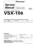
Electronic Control Circuit Diagram
Q1
Q7: KRA106M
(DTA143ZS)
Q7
Q1: KRA105M
(DTA123JS)
5V
C10
R3
10K
25V
0.1µ
C4
COM
IC2
OUT
D17
7812
25V
25V
1000µ 0.1µ
Q2
-5V
Q2, Q3, Q4
KRA106M
(DTA143ZS)
Q3
C9
16V
0.01µ
Q4
BZ
R8
2.7K
R4
20k
+
C2
Q6
KRC101M
(DTC143ES)
D4
D2
IN
10K
R7
D1 - D4
TMP47C443N
TR
R28
10K
0V
C17
50V
0.1µ
+
R23 47Ω 1/2W
Q8 ~ Q10
KRA222M
(DTB123EA)
Q10
Q9
LED1
9
10
PHOTO
DETECTOR
UNIT
IC4
88
C18
25V
47µ
1
18
GREEN
YELLOW
RED
R12
~ LED5, LED9
QWN-KEY
FU1
C15
FAN MOTOR
CAPACITOR
250V 6µF
GR
RE
BL
BK
BK
WH
16V 10µF
C19
10K
R6
10K
R5
C16
E/SAVER
SW1
D10
TIMER
SW2
D11
SELECTOR
SW3
D12
POWER
SW4
D13
UP-KEY
SW5
D14
POWER SUPPLY
115V AC
60Hz
GREEN
24
GY
SW6
D15
1000P 50V
LED7, LED8
LED6
R11
LED2
R13
R14
HEATSINK
R11 ~ R18
150Ω x 8
LED9 COOL
LED8 ENERGY
SAVER
LED7 TIMER
LED6 ON/OFF
LED5 FAN
LED4 COOL/L
LED3 COOL/M
LED2 COOL/H
AF-08CRL
R16
R17
R18
R15
AF-08CRL
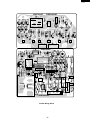
QPWBFB443JBZZ
JP28
JP35
1
DPWBFA246JBKZ
10
18
JP30
JP29
9
QPWBFB443JBZZ
C2
DPWBFA246JBKZ
Printed Wiring Board
25
AF-08CRL
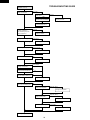
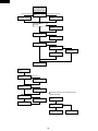
TROUBLESHOOTING GUIDE
No cooling
(Operation not at all.)
Measure the power supply
voltage at receptacle.
under 100V
120V(over 100V)
The house fuse or circuit
breaker open ?
not open.
open
Is it proper current capacity of the
house fuse or the circuit breaker ?
Ask the power supply
company for check.
Change the house fuse and
the circuit breaker turn on.
Is it sufficient current capacity
of power equipment ?
Is it small wiring for power
supply equipment ?
insufficient
Ask the power supply
company for check.
sufficient
Is plug disconnecting ?
disconnecting
Connect plug properly.
connecting
Check the power supply cord.
imperfect contact
OK
Change the power supply cord.
Check the fuse on PWB ass'y. open
Change the fuse on PWB ass'y.
OK
Measure the secondary
voltage of transformer.
under 14V(AC)
over 14V(AC)
Measure the voltage between NG
-12V and GND on PWB ass'y.
OK(12V, DC)
Measure the voltage between
-5V and GND on PWB ass'y.
NG
Change PWB ass'y.
OK(5V, DC)
If unit operate, dose the house
fuse or the circuit breaker open ?
NO
YES
Measure the insulation
resistance of compressor.
NG(under 10MΩ)
OK(over 10MΩ)
Change the compressor.
NG(under 10MΩ)
Measure the insulation
resistance of fan motor.
OK(over 10MΩ)
Change the fan motor.
Can the Compressor operate ? can't operate
can operate
Checking complete.
26
Change the compressor.
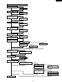
AF-08CRL
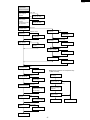
No cooling
(Fan operate but the
compressor doesn't operate.)
Measure the power
supply voltage at
receptacle.
under 100V
Ask the power supply
120V(over 100V) company for check.
insufficient
Is it sufficient current
capacity of power
equipment ?
Ask the power supply
Is it small wiring for power
company for check.
supply equipment ?
sufficient
Measure the current in
compressor circuit.
current
Check the
overload relay.
no current
imperfect contact
Change the
overload relay.
short
OK
Check the
running capacitor.
open
Check the
overload relay.
Change the
overload relay.
disconnecting
Is the connector
disconnecting ?
NG
connecting
Connect properly.
Change the running
capacitor.
OK
Check the compressor
relay.(MRY on PWB)
NG
OK
Change PWB ass'y.
Check the thermister.
NG
Change the thermistor.
OK
Measure the resistance
of compressor coil.
NG
Change the compressor.
OK
Is there high heat
source near the unit.
Checking method for the compressor relay.
(MRY on PWB)
Turn off the
power supply.
there is
Remove the high heat
source or stop.
there isn't
Measure the
resistance of its coil.
NG
OK(160Ω at 20˚C)
Is the outdoor
temperature too high ?
over 43˚C
under 43˚C
Check the outdoor heat
exchanger.
not dirty
Can the compressor
operate ?
can operate
Turn on the power
supplty as operating the
compressor.
Avoid sun light and
ventilate well for outdoor
heat exchanger.
Measure the
voltage to its coil.
dirty
NG
OK(12V, DC)
Clean them with steam
cleaner or another method.
OK
can't operate
Change the compressor.
Checking complete.
27
NG
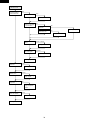
AF-08CRL
No cooling
(The compressor operate but
the fan motor doesn't operate)
crack at the solder part
Check BNC1 on PWB
ass'y
Repair with over solder.
disconnecting the connector
Connect the connector
properly.
OK
Check the fan motor
capacitor.
NG
OK
Measure the resistance
of compressor coil.
Change the fan motor
capacitor
NG
OK
Is the fan locked ?
Change the fan motor.
locked
Is the fan touched to
another parts ?
touch
Change fan or another
parts, or adjust.
no touch
Change the fan motor.
Checking complete
The compressor doesn't
turn off.
Check the thermister
connector.
disconnecting
Connect the connector
properly.
OK
Check the thermister
resistance.
NG
Change the thermister.
OK
Checking method for the compressor relay.
(MRY and PWB)
Check the compressor
relay.
OK
NG
Turn off the power
supply.
Change PWB ass'y.
Checking complete.
Measure the contact
resistance.
short
open
OK
28
NG
AF-08CRL
Insufficient cooling(Both compressor and compressor operate)
Check the temperature setting.
OK
too high
Set the lower temperature.
dirty
Check the air filter.
not dirty
Clean the air filter.
Is there high heat source or
any object restricting heat
radiation near the unit.
there is
Remove the high heat
source or stop.
there isn't
Check doors and windows.
close
Check the outdoor and indoor
heat exchanger.
open
Doors and windows
must be kept closed.
dirty
not dirty
Clean them with steam
cleaner or another method.
Calculate heat load wit using
Cooling load estimate form.
OK
Check rotating direction of
centrifugal fan.(to clockwise)
OK
Check changing fan speed
properly.
Undersized air conditioner
NG
Change unit to proper
sized air conditioner.
NG
Check the fan motor connector.
OK
NG
OK
Measure the resistance NG
of fan motor coil.
OK
Is the outdoor temperature
too high ?
Change the fan motor.
over 40˚C
Avoid sun light and ventilate well for
outdoor heat exchanger.
under 40˚C
Check the thermister.
OK
Connect properly.
NG
Change the thermister.
under 10˚C
Measure temperature difference
between inlet and outlet air at indoor.
over 10˚C
Is frost sticking to capillary tube ?
Or is indoor heat exchanger no cold ?
YES
Is the refrigerant leaked ?
NO
The capillary tube restrict,
and change the capillary tube.
NO
Measure the emperature
difference between discharge
tube and suction tube.
YES
Repair leakage and recharge
the refrigerant.
No temperature difference
The compressor is defective.
temperature difference
Change the compressor.
Checking complete.
29
AF-08CRL
Excessive vibration
or Abnormal noise
At fan only mode,
Excessive vibration
or Abnormal noise
YES
Check the air filter
dirty
NO
not dirty
Check rotating
direction of centrifugal
fan.(to clockwise)
OK
Clean the air filter.
NG
Check the fan motor
connector.
OK
Measure the resistance
of fan motor coil.
OK
Is the fan deformed or
broken.
OK
Is loosened screw
and nut fixing fan ?
OK
deform or broken
Change the fan
loosened
Tighten up.
Checking complete
Is each screws
loosened ?
loosen
OK
Is pipe touching to
another parts.
Tighten up
touching
Repair with adjusting
shape of pipes.
OK
Check mounting of
compressor.
OK
Check compressor
noise and vibration.
OK
NG
Repair mounting or
change compressor
cushion.
too big
Change compressor.
Checking complete
30
NG
Connect properly.
NG
Change the fan motor.
AF-08CRL
COOLING LOAD ESTIMATE FORM
INSTRUCTIONS FOR USING COOLING LOAD ESTIMATE FORM FOR ROOM AIR CONDITIONERS
(AHAM PUB. NO. RAC-1)
A. This cooling load estimate form is suitable for estimating the cooling load for comfort air conditioning installations
which do not require specific conditions of inside temperature and humidity.
B. The form is based on an outside design temperature of 95˚F dry bulb and 75˚F wet bulb. It can be used for areas in
the continental United States having other outside design temperature by applying a correction factor for the
particular locality as determined from the map.
C. The form includes "day" factors for calculating cooling loads in rooms where daytime comfort (such as living rooms,
offices, etc.).
D. The numbers of the following paragraphs refer to the correspondingly numbered item on the form:
1. Multiply the square feet of window area for each exposure by the applicable factor. The window area is the area
of the wall opening in which the window is installed. For windows shaded by inside shades or venetian blinds, use
the factor for "Inside Shades". For windows shades by outside awnings or by both outside awnings and inside
shades (or venetian blinds), use the factor for "Outside Awnings". "Single Glass" includes all types of single
thickness windows, and "Double Glass" includes sealed air space types, storm windows, and glass block. Only
one number should be entered in the right-hand column for item 1, and this number should represent only the
exposure with the largest load.
2. Multiply the total square feet of all windows in the room by the applicable factor.
3a. Multiply the total length (linear feet) of all walls exposed to the outside by the applicable factor. Doors should be
considered as being part of the wall. Outside walls facing due north should be calculated separately from outside
walls facing other directions. Walls which are permanently shaded by adjacent structures should be considered
as being "North Exposure". Do not consider trees and shrubbery as providing permanent shading. An insulated
frame wall or a masonry wall 8 inches or less in thickness is considered "Light Construction". An insulated frame
wall or a masonry wall over 8 inches in thickness is considered "Heavy Construction".
3b. Multiply the total length (linear feet) of all inside walls between the space to be conditioned and any unconditioned
spaces by the given factor. Do not include inside walls which separate other air conditioned rooms.
4. Multiply the total square feet of roof or ceiling area by the factor given for the type of construction most nearly
describing the particular application. (Use one line only.)
5. Multiply the total square feet of floor area by the factor given. Disregard this item if the floor is directly on the
ground or over a basement.
6. Multiply the number of people who normally occupy the space to be air conditioned by the factory given. Use a
minimum of 2 people.
7. Determine the total number of watts for lights and electrical equipment, except the air conditioner itself, that will
be in use when the room air conditioning is operating. Multiply the total wattage by the factor given.
8. Multiply the total width (linear feet) of any doors or arches which are continually open to an unconditioned space
by the applicable factor.
NOTE: Where the width of the doors or arches is more than 5 feet, the actual load may exceed the calculated
value. In such cases, both adjoining rooms should be considered as a single large room, and the room air
conditioner unit or units should be selected according to a calculation made on this new basis.
9. Total the loads estimated for the foregoing 8 items.
10. Multiply the sub total obtained in item 9 by the proper correction factor, selected from the map, for the particular
locality. The result is the total estimated design cooling load in BTU per hour.
E. For best results a room air conditioner unit or units having a cooling capacity rating (determined in accordance with
the NEMA Standards Publication for Room Air Conditioners, CN 1-1960) as close as possible to the estimated load
should be selected. In general, a greatly oversized unit which would operate intermittently will be much less
satisfactory than one which is slightly undersized and which would operate more nearly continuously.
F. Intermittent loads such as kitchen and laundry equipment are not included in this form.
31
AF-08CRL
BTU/Hr
(Quantity
x Factor)
FACTORS
HEAT GAIN FROM
QUANTITY
DAY
No
Shades
1. WINDOWS: Heat gain from sun.
Northeast
Southeast
South
Southwest
Southeast
West
Northwest
North
Inside
Shades
Outside
Shades
20
25
20
20
30
45
35
0
(Area a
Factor)
Use
only
the
largest
load
Use
only
only
60
25
80
40
75
30
75
35
110
45
sq ft
150
65
sq ft
sq ft
120
50
sq ft
0
0
These factors are for single glass only. For glass block, multiply the above factors
by 0.5: for double-glass or storm windows, multiply the above factors by 0.8.
sq ft
sq ft
sq ft
2. WINDOWS: Heat gain by conduction.
(Total of all windows)
Single glass
Double glass or glass block
14
7
sq ft
sq ft
Light Construction
3. WALLS: (Based on linear feet of wall.)
a. Outside walls
Noth exposure
Other than North exposure
b. Inside Walls (between conditioned
and unconditioned spaces only)
ft
ft
4. ROOF OR CEILING: (Use one only.)
a. Roof, uninsulated
b. Roof, 1 inch or more insulation
c. Ceiling, occupied space above.
d. Ceiling, insulated with attic space
above
e. Ceiling, uninsulated, with attic space
above
5. FLOOR: (Disregard if floor is directly
on ground or over basement.)
Heavy Construction
20
30
30
60
ft
30
sq ft
sq ft
sq ft
19
8
3
sq ft
5
sq ft
12
sq ft
3
600
6. NUMBER OF PEOPLE:
7. LIGHTS AND ELECTRICAL
EQUIPMENT IN USE
3
watts
8. DOORS AND ARCHES
CONTINUOUSLY OPENED TO
UNCONDITIONED SPACE:
(Linear feet of width.)
300
ft
9. SUB-TOTAL
xxxxx
10. TOTAL COOLING LOAD:
(BTU per hour to be used for selection
of room air conditioner(s).)
xxxxx
(Item 9) x
(Factor from Map) =
FARGO
ROCHESTER
EUGENE
ALBANY
GREEN BAY
NEW HAVEN
RENO
SACRAMENT
FRESNO
LAS VEGAS
PUEBLO
WICHITA
COLUMBIA
BIRMINGHAM
PHOENIX
ATLANTA
SAN ANTONIO
32
AF-08CRL
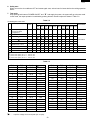
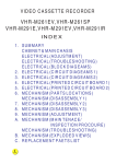
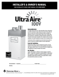
RUNNING CONDITION
Note:
1. Select mode of the Running Condition of a Room Air Conditioner.
SELECTOR .................................................................................................... HIGH COOL
THERMOSTAT .............................................................................................. 64˚F
2. Data of Performance Curve is measured between 40%RH and 70%RH.
If you measure the Room Air Conditioner above or below this rating, the data may miss the range of the
performance curve.
3. Outlet air temp. is influenced by the method of measurement. Measurement examples are shown.
4. Use power input data when checking the Running Condition.
RUNNING CONDITION FOR
PERFORMANCE CURVE
900
40%RH
Power input (W)
800
70%RH
700
600
40%RH
Line current(Amp.)
500
7
70%RH
6
5
Outlet air temp˚C (˚F)
30
(86)
70%RH
20
(68)
40%RH
10
(50)
25
(77)
30
(86)
35
(95)
Outside air temp.˚C (˚F)
33
40
(104)
AF-08CRL
PACKING AND ACCESSORIES
TOP PAD ASSEMBLY (DPADBA006JBFZ)
Top pad L
Top pad R
4
Accessories
Operation manual
Window sash foam seal
Window sash seal
Bottom gasket
Screws
Base pan angle
Right closure assembly
Left closure assembly
3
6
5
5
6
Packing case
(SPAKCB003JBEZ)
Front side
"Front side" mark
2
Protect
(SSAKHA245YDE0)
Enegry card
(TLAB-C219JBEZ)
Power supply cord
1
Bottom pad assembly
(CPADBA052JBKZ)
Detail is assembling
Energy card
34
AF-08CRL
REPLACEMENT PARTS LIST
REF. NO.
PART NO.
DESCRIPTION
Q'TY
CODE
1
1
1
1
1
1
1
1
1
3
1
1
1
1
1
1
1
1
1
1
1
1
1
1
1
4
1
1
3
2
1
1
1
1
1
1
1
1
1
1
1
2
BM
BA
AF
AF
BB
AS
AE
AF
AE
AC
AA
AC
AU
AU
AK
AV
AK
AB
AB
AB
AD
AC
AS
AD
AC
AC
AC
AC
AC
AF
AF
AB
AV
AB
AB
AC
AC
AC
AE
AE
AY
AC
1
1
1
1
2
1
1
1
1
1
1
1
1
1
3
1
1
1
AK
AD
AK
BF
AC
AC
AS
AB
AA
AD
AR
AM
AU
AK
AC
AD
AF
AA
1
1
1
1
1
CA
BP
BM
AP
AW
CABINET AND UNIT PARTS
1- 1
1- 2
1- 3
1- 4
1- 5
1- 6
1- 7
1- 8
1- 9
1-10
1-11
1-12
1-13
1-14
1-15
1-16
1-17
1-18
1-19
1-20
1-21
1-22
1-23
1-24
1-25
1-26
1-27
1-28
1-29
1-30
1-31
1-32
1-33
1-34
1-35
1-36
1-37
1-38
1-39
1-40
1-41
1-42
CMOTLB003JBEZ
DCHS-A364JBTB
PFPFPB137JBE0
PFPFPB138JBE0
CCAB-A318JBKZ
CWAK-C205JBKZ
HPNLCA805JBFC
HPNLCA816JBEA
PSEL-B825JBE0
LBND-A042JBE0
LHLDW0364JBE0
PSHE-A172JBE0
NFANPA078JBF0
NFANSA027JBF0
PFILMA164JBEA
PKESPA034JBF0
PKESPA057JBF0
PSEL-A827JBE0
PSEL-A994JBE0
PSEL-A828JBE0
TLABMA309JBRZ
PSEL-C085JBEZ
PSKR-A104JBF0
PSRA-A078JBF0
MJNTPA090JBFA
MLOV-A333JBFA
MJNTPA089JBFA
MLOV-A321JBFA
MLOV-A322JBFA
MSPR-A148JBEZ
LANG-A213JBTA
LPLTMA087JBP0
GWAKPA151JBFA
PSEL-B845JBE0
TLABBA110JBRA
TLABKA564JBE0
TLAB-C219JBEZ
TSPC-E155JBRZ
LHLD-A315JBF0
PFPFPB745JBE0
DSKR-A124JBKZ
LANG-A472JBPZ
Fan motor
Base pan ass’y
Base pan insulator
Base pan insulator
Cabinet ass’y
Top duct ass’y
Control panel
Control panel
Insulator
Wire fixing band
Wire holder
Protect sheet
Propeller fan
Centrifugal fan
Air filter
Condenser shroud
Orifice
Evaporator insulator
Orifice insulator
Motor insulator
Feature card
Tube insulator
Bulkhead
Drain tray
Louver link
Horizontal louver
Louver joint
Vertical louver A
Vertical louver B
Louver spring
Top inst.angle
Condenser cover
Front panel
Insulator
Sharp badge
Number card
Energy card
Name badge
Thermistor holder
Comp-cushion
Bulkhead ass’y
Cabinet angle
CONTROL BOX PARTS
2- 1
2- 2
2- 3
2- 4
2- 5
2- 6
2- 7
2- 8
2- 9
2-10
2-11
2-12
2-13
2-14
2-15
2-16
2-17
2-18
DPLT-A056JBWZ
LBNDKA058JBWZ
DPLT-A038JBW0
DPWBFA246JBKZ
PSPA-A084JBE0
PSPA-A085JBE0
QACC-A260JBZZ
QFS-AA048JBE0
TLABCB604JBRZ
QW-VZC561JBE0
QW-VZD376JBE0
RC-HZA256JBE0
RC-HZA136JBE0
RH-HXA006JBZZ
LBND-A042JBE0
QW-VZC366JBE0
PPLT-A300JBEZ
PPLT-A305JBEZ
Cont. box angle ass’y
Capacitor clamp
Cont. box cover ass’y
Control board unit
Spacer
Spacer
Power supply cord
Fuse
Wiring diagram
Lead wire
Compressor cord
Fan motor capacitor
Running capacitor
Thermistor
Wire fixing band
Lead wire
Insulating sheet
Insulating sheet
33333-
PCMPRA327JBEZ
PCON-A483JBEZ
PEVA-A423JBEZ
DCPY-A282JBKZ
RHOG-A130JBE0
Compressor
Condenser
Evaporator
Capillary tube ass’y
Overload relay
CYCLE PARTS
1
2
3
4
5
35
AF-08CRL
REF. NO.
PART NO.
DESCRIPTION
3- 6
3- 7
3- 8
3- 9
3-10
3-11
3-12
3-13
PSEL-A150JBE0
CPIP-A012JBKZ
PPIPCC085JB10
PPIPCF110JB1Z
GLEG-A073JBE0
MSPR-A005JBE0
PCOV-A002JBE0
PSEL-A006JBE0
Gasket washer
Suction tube ass’y
Lead tube
Discharge tube
Compressor cushion
Protector spring
Terminal cover
Terminal gasket
4- 1
4- 2
4- 3
4- 4
4- 5
4- 6
4- 7
4- 8
4- 9
4-10
4-11
4-12
4-13
4-14
4-15
4-16
4-17
4-18
TINSEA301JBRZ
DX-BZA016JBK0
SSAKAA018YDE0
XCTSD40P10000
XMPSD40P25000
LANGAA030JBTA
PSEL-A351JBE0
PSEL-A931JBE0
PSEL-A932JBE0
LANGAA012JBFE
SPADBB452YDE0
SSAKHA246YDE0
CRMC-A526JBEZ
LHLD-A389JBFB
PPLTPA016JBFB
UBATUA027JBE0
CFZK-B937JBKZ
LANGAA011JBFE
Operation manual
Screws kit
Bag
Tapping screw
Wood screw
Base pan angle
Window insulator
Window insulator
Window insulator
Right closure frame
Cardboard
Bag
Remote control
Controller holder
Closure
Battery pack
Closure ass’y
Left closure frame
Q'TY
CODE
1
1
1
1
3
1
1
1
AA
AU
AC
AM
AD
AB
AE
AC
1
1
1
6
7
2
1
1
1
1
1
1
1
1
2
1
1
1
AE
AW
AB
AA
AA
AD
AB
AH
AE
AH
AD
AH
AT
AC
AK
AE
BA
AH
1
1
1
1
1
2
AK
AP
AQ
AB
AB
AC
1
1
3
5
4
2
4
1
4
3
1
2
2
3
2
3
10
3
AA
AC
AA
AA
AA
AB
AB
AB
AB
AC
AB
AA
AA
AB
AA
AA
AA
AA
ACCESSORY PARTS
PACKING PARTS
5-1
5-2
5-3
5-4
5-5
5-6
DPADBA006JBFZ
CPADBA052JBKZ
SPAKCB003JBEZ
SSAKHA245YDE0
SSAKAA053YDE0
SPAD-A075JBE0
Top pad ass’y
Bottom pad ass’y
Packing case
Protect
Bag
Comp holder HA
6-1
6-2
6-3
6-4
6-5
6-6
6-7
6-8
6-9
6-10
6-11
6-12
6-13
6-14
6-15
6-16
6-17
6-18
LX-NZA002JBE0
LX-BZA236JBE0
XTPSD40P08000
XHTSD40P10000
XHTSD40P08000
XBPSD40P12J00
LX-BZA140JBE0
LX-BZ0107CBE0
LX-CZA038WRE0
LX-NZA026JBE0
LX-NZA074JBE0
XCTSD40P06000
XCTWJ40P16000
LX-BZA172JBE0
XTTSD40P10000
XTTSD40P12000
XTTSD40P14000
XTTSD40P20000
Special nut
Special screw
Tapping screw
Tap tight screw
Tap tight screw
Machine screw
Special screw
Special screw
Special screw
Special nut
Special nut
Tapping screw
Tapping screw
Special screw
Tapping screw
Tapping screw
Tapping screw
Tapping screw
SCREWS AND NUTS
HOW TO ORDER REPLACEMENT PARTS
To have your order filled prompty and correctly, please furnish the following information.
1. MODEL NUMBER
2. REF. NO.
36
3. PART NO.
4. DESCRIPTION
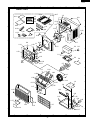
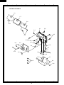
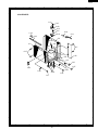
AF-08CRL
1
2
3
4
5
6
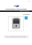
CABINET PARTS
A
4-11
1-5
4-15
4-3
4-4
4-5
4-2
6-14
4-10
4-12
B
A
4-17
4-18
6-9
6-17
1-31
6-7
B
4-8
4-13
4-16
4-14
1-13
4-9
4-1 4-7
1-34
6-14
6-4
4-6
6-12
6-15
6-11
C
C
1-9
6-4
1-41
6-18
6-7
1-16
1-20 1-1
6-15
5-3
1-36
6-18
1-23
5-6
1-40
D
D
5-1
1-10
5-2
5-4
1-22
1-12
1-11
2-7
6-17
E
E
1-6
1-29
5-5
1-28
1-26
6-2
1-30
1-14
F
1-27
6-17
1-3
F
1-4
1-25
1-17
1-24
6-13
1-42
6-8
6-9
G
G
1-35
6-9 1-42
6-17
1-37
1-38
1-33
1-15
6-13
1-2
1-21
H
6-17
1
2
3
4
37
5
6
H
AF-08CRL
1
2
3
4
5
6
CONTROL BOX PARTS
A
A
1-8
1-7
B
B
2-4
2-18
2-1
C
2-6
C
6-5
2-5
6-3
D
D
6-16
6-6
2-2
2-4
2-13
2-12
6-4
6-4
E
E
2-7
2-14
6-5
2-8
6-5
2-10
2-17
F
2-3
2-15
F
2-9
6-16
G
G
H
H
1
2
3
4
38
5
6
AF-08CRL
1
A
2
3
4
5
6
A
CYCLE PARTS
6-1
3-6
3-12
3-11
B
B
3-5
3-13
1-19
2-16
2-11
1-18
3-2
6-10
C
C
3-9
3-3
3-1
6-7
6-17
3-7
1-32
3-8
D
D
3-4
1-10
6-17
1-39
6-10
2-10
3-10
E
E
6-17
6-5
F
F
G
G
H
H
1
2
3
4
39
5
6
AF-08CRL
COPYRIGHT © 2002 BY SHARP CORPORATION
ALL RIGHTS RESERVED.
No part of this publication may be reproduced,
stored in retrieval systems, or transmitted in any
form or by any means, electronic, mechanical,
photocopying, recording, or otherwise, without prior
written permission of the publisher.
’02 SHARP CORP. 3S0.85E) Printed in U.S.A.
40