1
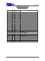
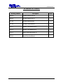
® Advanced Test Equipment Rentals www.atecorp.com 800-404-ATEC (2832) E stablished 1981 OPERATION AND SERVICE MANUAL MODEL HS-8A & HS-16 High Voltage and High Current Scanning systems (Compatible with Associated Research HypotULTRA II model 7550DT and QUADCHEK II model 7564SA) SERIAL NUMBER Models HS-8A/HS16 Item 37877 Ver 1.04 © Associated Research, Inc., 2000 13860 West Laurel Drive Lake Forest, Illinois, 60045-4546 U.S.A. Printed Jul 26, 2000 i CERTIFICATE OF CALIBRATION Associated Research, Inc., certifies that the instrument listed in this manual meets or exceeds published manufacturing specifications. This instrument was calibrated using standards that are traceable to the National Institute of Standards and Technology (NIST). WARRANTY This new instrument is warranted to be free from defects in workmanship and material for one year from the date of shipment, provided, the Owners Registration Card is returned within (15) days from receipt of the unit and there is no evidence of modifications, tampering or physical damage. Elimination of any connections in the earth grounding system or by-passing any safety systems will void this warranty. THIS WARRANTY DOES NOT COVER BATTERIES OR ACCESSORIES NOT OF ASSOCIATED RESEARCH MANUFACTURE. Any unit found defective under this warranty will be repaired free of charge if returned to the factory prepaid and insured. Except as provided herein, Associated Research makes no warranties to the purchaser of this unit and all other warranties, express or implied (including, without limitation merchantability or fitness for a particular purpose) are hereby excluded, disclaimed and waived. ii TABLE OF CONTENTS SECTION I GENERAL INFORMATION.................................................................... 1 SAFETY .............................................................................................................................................2 SECTION II HS-8A........................................................................................................ 7 SPECIFICATIONS .............................................................................................................................8 PANEL LAYOUTS.............................................................................................................................9 OPERATING HS-8A WITH HYPOTULTRA II......................................................... 11 DESCRIPTION .................................................................................................................................11 INTERCONNECT CABLES .............................................................................................................11 SETUP ..............................................................................................................................................12 OPERATION ....................................................................................................................................12 GPIB CONTROL ..............................................................................................................................13 OPERATING HS-8A WITH THE QUADCHEK II .................................................... 14 DESCRIPTION .................................................................................................................................14 INTERCONNECT CABLES .............................................................................................................14 SETUP ..............................................................................................................................................15 OPERATION ....................................................................................................................................16 GPIB CONTROL ..............................................................................................................................17 SECTION III HS-16 ..................................................................................................... 19 SPECIFICATIONS ...........................................................................................................................20 PANEL LAYOUTS...........................................................................................................................21 DESCRIPTION .................................................................................................................................24 INTERCONNECT CABLES .............................................................................................................24 GPIB CONTROL ..............................................................................................................................25 RS-232 CONTROL ...........................................................................................................................28 SECTION IV SERVICE MANUAL ............................................................................ 31 REPLACEMENT PARTS LIST ........................................................................................................32 SCHEMATICS..................................................................................................................................33 iii SECTION I GENERAL INFORMATION 1 SAFETY SAFETY PRECAUTIONS REQUIRED FOR HIGH VOLTAGE TESTING! GENERAL: This product and its related documentation must be reviewed for familiarization with safety markings and instructions before operation. This product is a Safety Class I instrument (provided with a protective earth terminal). Before applying power verify that the instrument is set to the correct line voltage (110 or 220) and the correct fuse is installed. SAFETY SYMBOLS: INSTRUCTION MANUAL SYMBOL. PLEASE REFER TO THE INSTRUCTION MANUAL FOR SPECIFIC WARNING OR CAUTION INFORMATION TO AVOID PERSONAL INJURY OR DAMAGE TO THE PRODUCT. INDICATES HAZARDOUS VOLTAGES MAY BE PRESENT. CHASSIS GROUND SYMBOL. WARNING CAUTION 2 CALLS ATTENTION TO A PROCEDURE, PRACTICE, OR CONDITION, THAT COULD POSSIBLY CAUSE BODILY INJURY OR DEATH. CALLS ATTENTION TO A PROCEDURE, PRACTICE, OR CONDITION, THAT COULD POSSIBLY CAUSE DAMAGE TO EQUIPMENT OR PERMANENT LOSS OF DATA. SAFETY WARNING: A Hipot produces voltages and currents which can cause harmful or fatal electric shock. To prevent accidental injury or death, these safety procedures must be strictly observed when handling and using the test instrument. SERVICE AND MAINTENANCE User Service To prevent electric shock do not remove the instrument cover. There are no user serviceable parts inside. Refer servicing to an Associated Research, Inc. authorized service center. Schematics, when provided, are for reference only. ASSOCIATED RESEARCH, INC. 13860 WEST LAUREL DRIVE LAKE FOREST, IL., 60045 -4546 U.S.A. PHONE: 1 (847) 367-4077 1 (800) 858-TEST (8378) FAX: 1 (847) 367-4080 E-MAIL : [email protected] http://www.asresearch.com Service Interval The instrument and its power cord, test leads, and accessories must be returned at least once a year to an Associated Research authorized service center for calibration and inspection of safety related components. Associated Research will not be held liable for injuries suffered if the instrument is not returned for its annual safety check and maintained properly. User Modifications Unauthorized user modifications will void your warranty. Associated Research will not be responsible for any injuries sustained due to unauthorized equipment modifications or use of parts not specified by Associated Research. Instruments returned to Associated Research with unsafe modifications will be returned to their original operating condition at your expense. TEST STATION Location Select an area away from the main stream of activity which employees do not walk through in performing their normal duties. If this is not practical because of production line flow, then the area should be roped off and marked for HIGH VOLTAGE TESTING. No employees other than the test operators should be allowed inside. If benches are placed back-to-back, be especially careful about the use of the bench opposite the test station. Signs should be posted: "DANGER - HIGH VOLTAGE TEST IN PROGRESS - UNAUTHORIZED PERSONNEL KEEP AWAY." 3 SAFETY Power Dielectric Voltage-Withstand Test Equipment must be connected to a good ground. Be certain that the power wiring to the test bench is properly polarized and that the proper low resistance bonding to ground is in place. Power to the test station should be arranged so that it can be shut off by one prominently marked switch located at the entrance to the test area. In the event of an emergency, anyone can cut off the power before entering the test area to offer assistance. Work Area Perform the tests on a nonconducting table or workbench, if possible. If you cannot avoid using a conductive surface, be certain that it is securely grounded to a good earth ground and insulate the high voltage connection from the grounded surface. There should not be any metal in the work area between the operator and the location where products being tested will be positioned. Any other metal in the work area should be connected to a good ground, never left "floating". Position the tester so the operator does not have to reach over the product under test to activate or adjust the tester. If the product or component being tested is small, it may be possible to construct guards or an enclosure, made of a non-conducting material such as clear acrylic, such that the item being tested is within the guards or enclosure during the test, and fit them with switches so that the tester will not operate unless the guards are in place or the enclosure closed. Keep the area clean and uncluttered. All test equipment and test leads not absolutely necessary for the test should be removed from the test bench and put away. It should be clear to both the operator and to any observers which product is being tested, and which ones are waiting to be tested or have already been tested. Do not perform Hipot tests in a combustible atmosphere or in any area where combustible materials are present. TEST OPERATOR Qualifications This instrument generates voltages and currents which can cause harmful or fatal electric shock and must only be operated by a skilled worker trained in its use. The operator should understand the electrical fundamentals of voltage, current, and resistance. They should recognize that the test instrument is a variable high-voltage power supply with the return lead directly connected to earth ground and therefore, current from the high-voltage output will flow through any available ground path. 4 SAFETY Safety Procedures Operators should be thoroughly trained to follow these and all other applicable safety rules and procedures before they begin a test. Defeating any safety system should be treated as a serious offense and should result in severe penalties, such as removal from the Hipot testing job. Allowing unauthorized personnel in the area during a test should also be dealt with as a serious offense. Dress Operators should not wear jewelry which could accidentally complete a circuit. Medical Restrictions This instrument should not be operated by personnel with heart ailments or devices such as pacemakers. TEST PROCEDURES !NEVER PERFORM A HIPOT TEST ON ENERGIZED CIRCUITRY OR EQUIPMENT! If the instrument has an external safety ground connection be sure that this is connected. Then connect the return (ground) lead first for any test regardless of whether the item under test is a sample of insulating material tested with electrodes, a component tested with the high voltage test lead, or a cord-connected device with a two or three prong plug. Plug in the high voltage test lead only when it is being used. Handle its clip only by the insulator---never touch the clip directly. Be certain that the operator has control over any remote test switches connected to the Hipot. Before turning on the Hipot, rotate the voltage control to its full counterclockwise position. Double check the return (ground) and high voltage connections to be certain that they are proper and secure. NEVER TOUCH THE ITEM UNDER TEST OR ANYTHING CONNECTED TO IT WHILE HIGH VOLTAGE IS PRESENT DURING THE HIPOT TEST. At the end of a test, once again rotate the voltage control to its maximum counterclockwise position and check the meter to be sure the voltage across the item under test has dropped to zero before disconnecting the test leads. When testing with DC, always discharge the capacitance of the item under test and anything the high voltage may have contacted--such as test fixtures--before handling it or disconnecting the test leads. HOT STICK probes can be used to discharge any capacitance in the item under test as a further safety precaution. A hot stick is a nonconducting rod about two feet long with a metal probe at the end which is connected to a wire. To discharge the device under test, two hot sticks are required. First connect both probe wires to a good earth ground. Then touch one probe tip to the same place the return lead was connected. While holding the 5 SAFETY first probe in place, touch the second probe tip to the same place where the high voltage lead was connected. Again, check the meter to be sure the voltage has dropped to zero. KEY SAFETY POINTS TO REMEMBER: • • • • • 6 Keep unqualified and unauthorized personnel away from the test area. Arrange the test station in a safe and orderly manner. Never touch the product or connections during a test. In case of any problem, turn off the high voltage first. Properly discharge any item tested with DC before touching connections. SECTION II Model HS-8A 7 SPECIFICATIONS MODEL HS-8A SPECIFICATIONS Maximum High Voltage rating 5kV DC & AC Maximum Current rating 30 amperes Number of high voltage outputs 8 Number of high current outputs 8 HV output Termination’s 100 ft reel HV cable rated for up to 30 kV with 8 connectors. Dimensions 17 x 5.8 x 13 inches W x H x D (432 x 147 x 330 mm) Weight 10.12 lbs. (4.6 kg) 8 PANEL LAYOUT FRONT PANEL LAYOUT 1 2 3 4 1. POWER INDICATOR: Lights when the power switch of the host instrument is turned on. 2. HIGH VOLTAGE STATUS INDICATORS: These LED’s indicate the status of each individual output. If the red LED lights it indicates that the output is set as High (high voltage). If the green LED lights it indicates that the output is set as Low (return). 3. GROUND BOND STATUS INDICATORS: These LED’s are only active when the HS-8A is connected to the QUADCHEK II model 7564SA which has a Ground Bond test feature. The red LED will light to indicate which ground bond output is active. 4. HIGH VOLTAGE INDICATOR: This LED will light when a high voltage test is activated through the host instrument. 9 PANEL LAYOUT REAR PANEL LAYOUT 1 2 3 5 6 4 7 8 1. CONTROL CONNECTOR: Interconnect port for connecting the control cable between the HS-8A and the host instrument. 2. HIGH CURRENT INPUT: Connector for input of high current output from QUADCHEK II model 7564SA. This connector is not used when the HS-8A is connected to the HypotULTRA II model 7550DT. 3. HIGH VOLTAGE INPUT: Connector for input of high voltage output from the host instrument. 4. HIGH VOLTAGE OUTPUTS: Eight individual output ports for high voltage tests (Dielectric Withstand and Insulation Resistance tests). 5. SAFETY GROUND CONNECTOR: Must be connected to a known good ground system to ensure operator safety. 6. RETURN INPUT: Connector for interconnecting the return of the host instrument with the HS-8A. 7. GROUND BOND RETURN: Common return connector for the Ground Bond test outputs. This connector is not used when the HS-8A is connected to the HypotULTRA II model 7550DT. 8. GROUND BOND OUTPUTS: Output ports for application of the high current for Ground Bond tests. The standard configuration of the HS-8A is for up to eight Ground Bond outputs. 10 HypotULTRA II OPERATION OF THE HS-8A WITH HypotULTRA II DESCRIPTION The optional HS-8A Scanning system can be easily interconnected to HypotULTRA II to enhance it’s testing capabilities. This section of this manual describes interconnecting and operating the optional HS-8A scanner with the HypotULTRA II model 7550DT. In order to fully understand this option you should also refer to the manual on the HypotULTRA II. This switching matrix allows HypotULTRA II to direct high voltage to any of eight individual output ports. This accessory is ideal for applications where multiple points of the same item need to be tested quickly and accurately. The Scanner is also applicable when high volume manufacturing calls for multiple item testing to save setup time. INTERCONNECT CABLES The HS-8A comes complete with the following hardware and interconnect cables to allow connection to HypotULTRA II. 1 1 1 8 1 12 25 pin control cable High voltage interconnect cable Return interconnect cable High voltage connectors and assembly instructions 100 foot (48.75 meter) reel of high voltage cable Ground Bond push-on crimp lugs The 25 pin control cable connects between the rear panel SCANNER 1 or SCANNER 2 connector of HypotULTRA II and the rear panel connector of the HS-8A. The High voltage interconnect cable is then connected from the high voltage rear output connector of the HypotULTRA II to the rear high voltage input of the HS-8A. The rear panel return of HypotULTRA II is connected to the rear panel return connection of the HS-8A. Eight high voltage connectors are provided as well as a reel of cable and assembly instructions so that each user can assemble the lengths of high voltage cable to meet their specific needs. WARNING Under certain conditions high voltage can appear on the cabinet of the HS-8A. The ground terminal on the rear panel of the HS-8A must be connected to a good earth ground to ensure operator safety. The HS-8A does not have it’s own power switch or any other user configurable switches. Power is provided through the HypotULTRA II and setup of the HS-8A is done through the HypotULTRA II control menu. The HS-8A can be interconnected to other Associated Research models that provide high current Ground Bond test capability. For this reason the HS-8A comes complete with high current input and output terminals and push-on crimp lugs. These high current 11 HypotULTRA II connections can be disregarded for interconnection to HypotULTRA II. For more information on other compatible products call 1-800-858-TEST (8378). SETUP Each of the 8 outputs of the HS-8A can be set as High (High Voltage), Low (Return) or Open. Parameter setup is done through the HypotULTRA II setup menu. If you are in the Withstand or Insulation Resistance test mode and you scroll through the HypotULTRA II setup menu, you will locate a screen that appears as shown below. Scanner Set CH = 1 - 16 XXXXXXXXXXXXXXXX Note: X = H, O or L. Scanner channels 1-8 refer to the HS-8A connected to the SCANNER 1 connector and channels 9-16 refer to HS-8A connected to the SCANNER 2 connector. Pressing the (1) key on the data entry keypad of HypotULTRA II sets the output as “High”. Pressing the (0) key sets the output as “Low”. Pressing the (.) key disables the output and leaves it open and isolated from the other outputs. The user can setup an individual output within each step and then CONNECT the steps together in order to sequentially test through each output. Setup can also be configured so that a single step can activate all 8 outputs. Once each output has been configured the operator must press the ENTER key on HypotULTRA II in order for the input to be accepted. EXAMPLE OF SETTING UP THE HS-8A The following example demonstrates how a user would setup outputs one and two as “High”, outputs three and four as “Low” and outputs five through eight as “Open”. All channels are preset as “Open” from the factory. From the Scanner setup screen the user would press “1100” and then press ENTER. All channels not specified will be set to Open. The Scanner setup screen should now appear as follows: Scanner Set CH = 1 - 16 HHLLOOOOOOOOOOOO OPERATION Once the HS-8A is interconnected to HypotULTRA II the “power on” LED will light as soon as the Power switch of the HypotULTRA II is turned on. The HS-8A will activate as soon as the Test switch of HypotULTRA II is pressed. A master LED indicator on the HS-8A indicates when high voltage is activated. Individual LED indicators for each output provide an indication of whether the output is set as High, Low or Open. If the high voltage output is set as “High” the red LED will light. If the high voltage output is set as “Low” the green LED will light. If the high voltage output is “Open” then no LED will light. 12 HypotULTRA II When the Stop on Fail feature has been turned ON and a failure is detected, the test will stop, high voltage will be deactivated and the HypotULTRA II will give a visual and audible indication of failure. If steps were connected to sequence through the outputs, then the test will stop and HypotULTRA II will indicate failure once it reaches the output that was connected to the defective device. The HS-8A will not continue on to test the other outputs until the Reset switch is pressed, the defective item is removed, and the Test switch is pressed once again. The HS-8A will then begin to test from the first setup in the program. CAUTION Multiple outputs can be set to activate simultaneously. However, when configured this way the HS-8A cannot provide an indication of which output detected failure. Therefore, each item or test point would again have to be re-tested individually if the operator needs to determine the exact point of failure. SETUP OF THE HS-8A THROUGH GPIB Through the host instrument the parameters for the HS-8A can be setup through GPIB control. Please refer to the HypotULTRA II instrument owners manual for more details on GPIB control. The commands for the scanner are as follows: SG = AC Withstand test channel SQ = DC Withstand test channel SX = Insulation resistance test channel To set the Withstand and Insulation resistance test channels the user needs to enter a letter string after the command to set the outputs as High, Low or Open. H = High L = Low O = Open As an example if the operator wished to set the AC Withstand output channels 1 & 2 as High, 3 & 4 as Low and 5 through 8 as Open the following command would be entered through GPIB control. “SGHHLLOOOO” 13 QUADCHEK II OPERATION OF THE HS-8A WITH QUADCHEK II DESCRIPTION The optional HS-8A Scanning system can be easily interconnected to QUADCHEK II to enhance it’s testing capabilities. This section of this manual describes interconnecting and operating the optional HS-8A scanner with the QUADCHEK II model 7564SA. In order to fully understand this option you should also refer to the manual on QUADCHEK II. This switching matrix allows QUADCHEK II to direct high voltage to any of eight individual output ports. Eight individual outputs are also provided for the high current Ground Bond test. This accessory is ideal for applications where multiple points of the same item need to be tested quickly and accurately. The Scanner is also applicable when high volume manufacturing calls for multiple item testing to save setup time. INTERCONNECT CABLES The HS-8A comes complete with the following hardware and interconnect cables to allow connection to QUADCHEK II. 1 1 1 1 8 1 12 25 pin control cable High voltage interconnect cable High Current Return interconnect cable High Current output interconnect cable High voltage connectors and assembly instructions 100 foot (48.75 meter) reel of high voltage cable Ground Bond push-on crimp lugs The 25 pin control cable connects between the rear panel SCANNER 1 or SCANNER 2 connector of QUADCHEK II and the rear panel connector of the HS-8A. The High voltage interconnect cable is then connected from the high voltage rear output connector of the QUADCHEK II to the rear high voltage input of the HS-8A. The rear panel return of QUADCHEK II is connected to the rear panel return input of the HS-8A. The rear panel current output of QUADCHEK II is connected to the rear panel input of the HS-8A. Eight high voltage connectors are provided as well as a reel of cable and assembly instructions so that each user can assemble the lengths of high voltage cable to meet their specific needs. WARNING Under certain conditions high voltage can appear on the cabinet of the HS8A. The ground terminal on the rear panel of the HS-8A must be connected to a good earth ground to ensure operator safety. The rear panel of the HS-8A also includes eight output terminals for the Ground Bond test current outputs. We recommend using standard 10 gauge wire for operation at 30 amps. The wires should be attached to the push-on lugs on the rear panel of the HS-8A utilizing the crimp on push-on lugs provided, to minimize connection resistance. Also, the wire lengths should be kept as short as possible to limit the affect of test lead resistance. 14 QUADCHEK II The HS-8A does not have it’s own power switch or any other user configurable switches. Power is provided through the QUADCHEK II and setup of the HS-8A is done through the QUADCHEK II control menu. HIGH VOLTAGE OUTPUT SETUP Each of the 8 outputs of the HS-8A can be set as High (High Voltage), Low (Return) or Open. Parameter setup is done through the QUADCHEK II setup menu. As you scroll through the QUADCHEK II setup menu you will locate a screen in the status window that appears as follows Scanner Set CH = 1 - 16 XXXXXXXXXXXXXXXX Note: X = H, O or L. Scanner channels 1-8 refer to the HS-8A connected to the SCANNER 1 connector and channels 9-16 refer to HS-8A connected to the SCANNER 2 connector. Pressing the (1) key on the data entry keypad of QUADCHEK II sets the output as “High”. Pressing the (0) key sets the output as “Low”. Pressing the (.) key disables the output and leaves it open and isolated from the other outputs. The user can setup an individual output within each step and then CONNECT the steps together in order to sequentially test through each output. Setup can also be configured so that a single step can activate all 8 outputs. The operator must select a status for each of the 8 outputs even if only intending to use several of them. Once each output has been configured the operator must press the ENTER key on QUADCHEK II in order for the input to be accepted EXAMPLE OF SETTING UP HIGH VOLTAGE TESTS THROUGH THE HS-8A The following example demonstrates how a user would setup outputs one and two as “High”, outputs three and four as “Low”, and outputs five through eight as “Open”. All channels are preset as “Open” from the factory. From the Scanner setup screen the user would press “1100” and then press ENTER. All channels not specified will be set to Open. The Scanner setup screen should now appear as follows: Scanner Set CH = 1 - 16 HHLLOOOOOOOOOOOO HIGH CURRENT OUTPUT SETUP The HS-8A also allows selection of up to eight output ports for applying the high current ground bond test. This setup differs slightly from the high voltage setup of the scanner. Unlike the high voltage outputs, the operator can only choose to activate one output for each test setup. If the application calls for multiple point Ground Bond testing, the user needs to CONNECT steps together in order to progress through up to eight outputs. While 15 QUADCHEK II in the Ground Bond setup mode the scanner setup screen in the status window will appear as follows: Scanner CH = Range: 1-16 0 0=OFF The operator then needs to enter the port number to activate using the keypad of the QUADCHEK II and then press the enter key. Scanner channels 1-8 refer to the HS-8A connected to the SCANNER 1 connector and channels 9-16 refer to HS-8A connected to the SCANNER 2 connector. The default value is set at 0 which deactivates the scanner in Ground Bond mode. OPERATION Once the HS-8A is interconnected to QUADCHEK II the “power on” LED will light as soon as the Power switch of the QUADCHEK II is turned on. The HS-8A will activate as soon as the Test switch of QUADCHEK II is pressed. A master LED indicator on the HS8A indicates when high voltage or high current is activated. Individual LED indicators provide an indication of whether the output is set as High, Low or Off. If the high voltage output is set as “High” the red LED will light. If the high voltage output is set as “Low” the green LED will light. If the high voltage output is “Off” then no LED will light. An additional set of LED’s indicate which high current Ground Bond output is active. If the high current output is active a red LED will light. When the Stop on Fail feature has been turned ON and a failure is detected, the test will stop, high voltage will be deactivated and the QUADCHEK II will give a visual an audible indication of failure. If memories were connected to sequence through outputs, the test will stop and QUADCHEK II will indicate failure once it reaches the output that was connected to the defective device. The HS-8A will not continue test the other outputs until the QUADCHEK II Reset switch is pressed, the defective item is removed, and the Test switch is pressed once again. The HS-8A will then begin to test from the first setup in the program. CAUTION Multiple high voltage outputs can be set to activate simultaneously. However, when configured this way the HS-8A cannot provide an indication of which output detected failure. Therefore, each item or test point would again have to be re-tested individually if the operator needs to determine the exact point of failure. 16 QUADCHEK II SETUP OF THE HS-8A THROUGH GPIB Through the host instrument the parameters for the HS-8A can be setup through GPIB control. Please refer to the QUADCHEK II instrument owners manual for more details on GPIB control. The commands for the scanner are as follows: SG = AC Withstand test channel SQ = DC Withstand test channel SX = Insulation resistance test channel S3 = Ground Bond test channel To set the Withstand and Insulation Resistance test channels the user needs to enter a letter string after the command to set the outputs as High, Low or Open. H = High L = Low O = Open As an example if the operator wished to set the AC Withstand output channels 1 & 2 as High, 3 & 4 as Low and 5 through 8 as Open the following command would be entered through GPIB control. “SGHHLLOOOO” The Ground Bond test channels are selected independently within each steps of the host instrument. Only one Ground Bond output can be activated in a single step location. The GPIB command is simply followed by a number indicating which output is to be activated. As an example if the operator wished to set Ground Bond output channel 2 as active the following command would be entered through GPIB control. “S32” 17 QUADCHEK II This page intentionally left blank. 18 SECTION III Model HS-16 19 SPECIFICATIONS MODEL HS-16 SPECIFICATIONS Input: 115 VAC (+15%), 47-63 Hz, Single Phase 230 VAC (+15%), 47-63 Hz, Single Phase User Selectable Fuse: 250 V - 5 Amp slow blow Control: 1 GPIB connection and 1 RS-232 connection Maximum High Voltage rating 5kV DC & AC Maximum Current rating 30 amperes Number of high voltage outputs 16 Number of high current outputs 16 HV output Termination’s 200 ft reel HV cable rated for up to 30 kV with 16 connectors. Dimensions 17 x 5.8 x 17 inches WxHxD (432 x 147 x 432 mm) Weight 22.6 lbs. (10.3 kg) 20 PANEL LAYOUTS HS-16 FRONT PANEL LAYOUT 1 2 3 4 1. POWER SWITCH: Rocker style switch with international ON (|) and OFF (0) markings. 2. HIGH VOLTAGE STATUS INDICATORS: These LEDs indicate the status of each individual High Voltage output. When the red LED lights, it indicates that the output is set as High (high voltage). When the green LED lights, it indicates that the output is set as Low (return). 3. GROUND BOND STATUS INDICATORS: These LEDs indicate the status of each individual Ground Bond output. The red LED will light to indicate which high current output is active. Only one channel can be active at one time. 4. POWER INDICATOR: Lights when the power switch is turned on. 21 PANEL LAYOUTS REAR PANEL LAYOUT 1 2 8 9 3 10 4 5 6 11 7 12 13 1. FUSE RECEPTACLE: To change the fuse unplug the power (mains) cord and turn the fuse receptacle counter-clockwise. The fuse compartment will be exposed. Please replace the fuse with one of the proper rating. 2. HIGH VOLTAGE INPUT: Connector for input of high voltage output from the host instrument. 3. SAFETY GROUND CONNECTOR: Must be connected to a known good ground system to ensure operator safety. 4. RETURN INPUT: Connector for interconnecting the return of the test instrument to the HS-16. 5. INPUT POWER SWITCH: Line voltage selection is set by the position of the switch. In the left most position it is set for 110-120 volt operation, in the right most position it is set for 220-240 volt operation. 6. HIGH CURRENT INPUT: Connector for input of high current output from an instrument with High Current Ground Bond capability such as QUADCHEK II model 7564SA. This connector is not used when the HS-16 is connected to the HypotULTRA II model 7550DT. 7. HIGH VOLTAGE OUTPUTS: 16 individual output ports for high voltage tests (Dielectric Withstand and Insulation Resistance tests). 8. GPIB ADDRESS SWITCH: This is an 8-pin DIP switch use to configure the GPIB address of each HS-16 in the system. 9. INPUT POWER RECEPTACLE: Standard IEC 320 connector for connection to a standard NEMA style line power (mains) cord. 10. GPIB: Standard connector for interconnection to the IEEE 488 Bus interface. 22 PANEL LAYOUTS 1 2 8 9 3 10 4 5 6 11 7 12 13 11. RS-232: Standard 9 pin D-Subminiature connector for interconnection to the RS-232 interface. 12. GROUND BOND RETURN: Common return connector for the Ground Bond test outputs. This connector is only active when a Ground Bond channel has been selected as is then connected to the main Return Input (item 4). 13. GROUND BOND OUTPUTS: Output ports for application of the high current for Ground Bond tests. The standard configuration of the HS-16 is for up to 16 Ground Bond outputs. 23 OPERATION DESCRIPTION Some test applications require more than eight outputs for testing multiple points of a single product. Additionally, in a production environment, time and money constraints require that multiple products be tested at the same time. The HS-16 accommodates both of these requirements. The HS-16 allows for multiple scanners to be controlled independently with either the HypotULTRA II or the QUADCHEK II. The HS-16 is connected directly to a computer via a GPIB cable. The HypotULTRA II or QUADCHEK II would be setup as a seperate device on the same bus. The output of the testers must be directly connected to the inputs of the HS-16 scanner(s). Standard GPIB commands are used to activate the selected outputs of the scanner(s). Since a GPIB bus will allow connection of up to 15 instruments, a total of up to fourteen HS-16’s and either a HypotULTRA II or QUADCHEK II could be connected to a single GPIB card. Total system capability on a single bus could accomodate 14 scanners which would allow 384 high voltage points to be tested. INTERCONNECT CABLES The HS-16 comes complete with the following hardware and interconnect cables to allow connection to HypotULTRA II or QUADCHEK II. HypotULTRA II 1 High voltage interconnect cable 1 Return interconnect cable 16 High voltage connectors and assembly instructions 1 200 foot (94.48 meters) reel of high voltage cable 18 Ground Bond push-on crimp lugs 1 RS-232 NUL Modem cable QUADCHEK II 1 High voltage interconnect cable 1 High Current Return interconnect cable 1 High Current interconnect cable 16 High voltage connectors and assembly instructions 1 200 foot (94.48 meters) reel of high voltage cable 18 Ground Bond push-on crimp lugs 1 RS-232 NUL Modem cable HIGH VOLTAGE TESTING The High voltage interconnect cable should be connected from the high voltage rear output connector of the HypotULTRA II or QUADCHEK II to the rear high voltage input of the HS-16. 16 high voltage connectors are provided as well as a reel of cable and assembly instructions so that each user can assemble the lengths of high voltage cable to meet their specific needs. 24 OPERATION The rear panel return output of HypotULTRA II or QUADCHEK II must be connected to the rear panel return input of the HS-16 when hipot testing. This connection is also used during Ground Bond testing with the QUADCHEK II. When the scanner channels are selected High or Low either the High Voltage or Return are switch through to the High Voltage output channels. When High is selected the output channel of the HS-16 will be connected to the High Voltage output of HypotULTRA II or QUADCHEK II. When Low is selected the output channel will be connected to the Return output from HypotULTRA II or QUADCHEK II. Setting the output channel to Open causes the channel to be isolated from both High Voltage and Return. Under certain conditions high voltage can appear on the cabinet of the HS-16. The ground terminal on the rear panel of the HS-16 must be connected to a good earth ground to ensure operator safety. WARNING GROUND BOND TESTING The rear panel Current and Return connection of the QUADCHEK II should be connected to the rear panel Return and Current connectors of the HS-16 with the High Current Return and High Current interconnect cables provided. This extends ground bond testing capability through the HS-16. The common (COM.) connections of the Ground Bond outputs should be used when ground bond testing. The ground bond test will be performed between the output channel selected and the ground bond common terminal. When an output channel is selected, the Current input terminal is connected to the output channel, and the Return input terminal is connected to the COM. terminals. The two COM. terminals are connected to the main Return input during ground bond operation, but are seperated from each other and disconnected from the main Return during high voltage operation. The HS-16 can be interconnected to other Associated Research models that provide high current ground bond test capability. For this reason the HS-16 comes complete with high current input and output terminals. These high current connections can be disregarded for interconnection to HypotULTRA II. For more information on other compatible products call 1-800-858-TEST (8378). GPIB INTERFACE CONTROL This section provides information on the proper use and configuration of the GPIB (IEEE488) remote interface. A Brief History of IEEE-488.... Hewlett-Packard designed in 1965 the Hewlett-Packard Interface Bus (HP-IB) to connect their line of programmable instruments to computers. This bus had high transfer rates (nominally 1 Mbytes/s), and thus quickly gained acceptance. Later, it was accepted as the IEEE Standard 488-1975 and has since evolved into ANSI/IEEE Standard 488.1-1987. 25 OPERATION IEEE-488 has expanded over the years and is used with many more types of computers and instruments than just HP. Because of this it is usually referred to as the General Purpose Interface Bus, (GPIB). GPIB Messages There are typically two types of messages that GPIB devices use to communicate with other interconnected GPIB devices; Interface messages: often called commands or command messages and Device dependent messages often called data or data messages. Data Messages: contain information such as programming instructions or measurement results. Command Messages perform functions such as initializing the bus and addressing and unaddressing devices. Functions A GPIB device can be a Listener, Talker and/or Controller. A Talker sends data messages to one or more Listeners, which receive data. A Controller manages the information flow on the GPIB by sending commands to all devices. The GPIB bus is much like a computer bus except a computer has circuit cards connected via a backplane and the GPIB has stand alone devices connected via a cable. Signals and Lines The GPIB consists of 16 signal lines and 8 ground-return or shield drain lines. The 16 signal lines are grouped into 8 data lines, 3 handshake lines and 5 interface management lines. Data Lines: The eight data lines, DI01 through DI08 carry data and command messages. The 7-bit ASCII or ISO code set is used and the eighth bit DI08 is unused. Handshake Lines: The transfer of message bytes between devices is done via three asynchronously control lines. Referred to as three-wire interlocked handshake. This guarantees that message bytes on the data lines are sent and received without transmission error. NRFD (not ready for data) indicates when a device is ready or not ready to receive a message byte. NDAC (not data accepted) indicates when a device has or has not accepted a message byte. DAV (data valid) tells when the signals on the data lines are stable (valid) and can be accepted safely by devices. Interface Management Lines: Five lines are used to manage the flow of information across the interface. 26 OPERATION ATN (attention) ATN is driven true by the controller when it uses the data lines to send commands, and drivers ATN false when a Talker can send data messages. IFC (interface clear) IFC is driven by the system controller to initialize the bus and become CIC. REN (remote enable) The REN line is driven by the controller which is used to place devices in remote or local program mode. SRQ (service request) The SRQ line can be driven by any device to asynchronously request service from the Controller. EOI (end or identify) This line has two purposes- the Talker uses this line to mark the end of a message string, and the Controller uses it to tell devices to identify their response in a parallel poll. GPIB Connector Connection is usually accomplished with a 24-conductor cable with a plug on one end and a connector at the other end. Devices may be connected in a linear, star or a combination configuration. The standard connector is the Amphenol or Cinch Series 57 Microribbon or AMP CHAMP type. The GPIB uses negative logic with standard transistor-transistor logic (TTL) levels. When DAV is true, for example, it is a TTL low level (≤ 0/8 V), and when DAV is false, it is a TTL high level (≥ 2.0 V). Restrictions and Limitations on the GPIB A maximum separation of 4 m between any two devices and an average separation of 2 m over the entire bus. A maximum total cable length of 20 m. No more than 15 device loads connected to each bus, with no less than two-thirds powered on. Note: A bus extender which is available from numerous manufacturers is available to overcome these limitations. GPIB CONTROL COMMANDS Ground Bond Port: GX X = 0 - 16, 0 = OFF High Voltage Port: WXXXXXXXX X = H (HIGH) or L (LOW) or O (OFF) EXAMPLES: To activate ground bond port number (1) the string “G1” would be sent. To set high voltage outputs (1-4) as high and outputs (5-8) as low the string “WHHHHLLLL” would be sent. 27 OPERATION GPIB ADDRESS SETUP This is an 8-pin DIP switch. Pins 1 through 5 are used to set the GPIB address. Pins 6 through 8 are not used. The DIP switch is set in the up position for ON and in the down position for OFF. The DIP switch is arranged from pin 1 to pin 5 according to the following Binary Code: PIN 1 PIN 2 PIN 3 PIN 4 PIN 5 = 1 = 2 = 4 = 8 = 16 The GPIB address number is the sum of the total binary code on the DIP switch. The GPIB address must be selected before turning “ON” the unit. EXAMPLES: If you wish to set the address number to 9, you must turn “ON” DIP switch pin 1 and pin 4 and turn “OFF” pin 2, pin 3 and pin 5. If you wish to set the address number to 8, you must turn “ON” DIP switch pin 4 and turn “OFF” pin 1, pin 2, pin 3 and pin 5. A default address number of 9 is set at the factory. RS-232 INTERFACE The RS-232 port on this instrument is a simple three wire design and does not impliment handshaking. The three lines are; transmit (TD), receive (RD), and signal ground. The HS16 is a listen only device and does not send back any responce to commands and will not indicate errors from incorrectly sent commands. The control command are the same as those used for GPIB control. RS-232 CONTROL COMMANDS Ground Bond Port: GX X = 0 - 16, 0 = OFF High Voltage Port: WXXXXXXXX X = H (HIGH) or L (LOW) or O (OFF) EXAMPLES: To activate ground bond port number (1) the string “G1” would be sent. To set high voltage outputs (1-4) as high and outputs (5-8) as low the string “WHHHHLLLL” would be sent. RS-232 CABLE The HS-16 is provided with 9 pin D-subminiature cable that is configured as a nul modem to provide proper signal connection between the host controller and the HS-16. If the user desires to create a different cable than the one provided, the cabling should be configured as follows for a 9 pin serial port interface: 28 OPERATION 7564SA/7550DT PC / Bus Controller RD 2 2 RD TD 3 3 TD SIG GND 5 5 SIG GND The COM port should have the following configuration; 9600 baud, 8 data bits, 1 stop bit, no parity. This interface does not support XON/XOFF protocol or any hardware handshaking. The controller should be configured to ignore the handshaking lines DTR (pin 4), DSR (pin 6) CTS (pin 8) and RTS (pin 7). If the port can not be configured through software to ignore the lines then the handshake lines should be jumpered together in two different sets. Pins 4 and 6 jumpered together and pins 7 and 8 jumpered together at the controller end of the cable. 29 OPERATION This page intentionally left blank. 30 SECTION IV SERVICE MANUAL 31 PARTS LIST Replacement Parts List Model HS-8A and HS-16 Rev. A, 11/23/99 ECO 4741 Part Number Qty. Reference Designator Description Model HS-8A and HS-16 37746 37571 37800 37801 37478 37697 1 1 2 2 9 , 17 1 CSU-105A - Scanner Matrix Board Earth Connector 3U Rack Mount Bracket 3U Rack Mount Handle High Voltage Connector IC Microcontroller 8-bit 20Mhz 89C52 CSU-CO2 DSP-08 Scanner Control Board Scanner Display Board HS16-CON CSW-01 DSP-09 - Main Control Board Input Protection Board Scanner Display Board Input Power Cable 10A/7Ft. Power Switch 2P 10A/250V Fuse Holder 20mm Fuse 3.15A 250V Slow Blow 20mm Feet Kit w/o Rubber Inserts Rubber Insert Model HS-8A only 37748 37873 1 1 Model HS-16 only 37875 37515 37874 33189 37555 37781 37930 38101 38102 1 1 1 1 1 1 1 1 4 Interconnect Accessories for Model HS-8A and HS-16 HS-8-11 1 Cable Assy. RETURN Interconnect HypotULTRA II HS-8-12 1 Cable Assembly HV Interconnect HS-8-13 8 pcs Cable Kit HV Output HS-8-14 1 Cable Assy. CURRENT Interconnect Quadchek II HS-8-15 1 Cable Assy RETURN Interconnect Quadchek II 37531 37863 37779 36534 32 1 1 1 100Ft HS-8A only HS-16 only - Cable Interconnect 25 Pin D-Subminiature Cable RS-232 15ft. 9 pin D-Sub (NULL-MODEM) Terminal Push-on 0.25in. 10-12 AWG Wire Stranded 18 AWG WHT 30KVDC 100ft. SCHEMATICS SCHEMATIC INDEX Drawing Number Description Pages SHS-8A Wiring Diagram HS-8A 1 SHS-16 Wiring Diagram HS-16 1 S37746 Scanner Matrix Board 1 S37748 Scanner Control Board 1 S37873 Display LED Board HS-8A 1 S37874 Display LED Board HS-16 1 S37875 Main Control Board HS-16 3 S37515 Input Protection Board 1 33