1
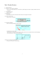
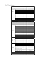
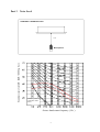
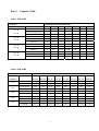
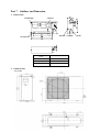
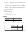
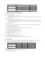
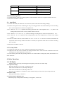
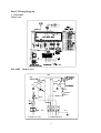
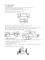
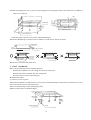
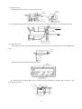
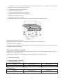
TECHNICAL & SERVICE MANUAL
CASSETTE TYPE AIR-CONDITIONER
(One-way cassette)
FSK-94HF
FI-SM-040830
One-way Cassette Air-conditioner
Table of Contants
Part 1.
Product Features
2
Part 2.
Specification
3
Part 3.
Noise Level
5
Part 4.
Velocity ﹠ temperature distribution
6
Part 5.
Operation Range
7
Part 6.
Capacity Table
8
Part 7.
Outlines and Dimension
9
Part 8.
Electric Control Functions
10
Part 9.
Wiring Diagram
16
Part 10.
Installation
17
Part 11
Servicing and Maintenance
23
Part 12.
Exploded view
26
NOTICE
Specifications are subject to change without notice for further improvement.
All the product information has been carefully checked.
1
Part 1. Product Features
1) Lower noise level
2) Smoother air flow with less turbulence
---Owing to the multiple-blade fan rotor and the air guide design, the airflow is getting smoother and more
comfortable
3) One direction air flow
---Quick cooling
4) Stylish design
---Be harmonious with any interior decoration and creates an elegant environment
5) Ultra thin machine body
---Space saving: only 235mm
6) Convenient installation
---Able to be flexibly installed in various corners
---Standardized sectional module
--- More flexible in routing the tube through the ceiling space due to the condensed water can be lift through
the drain pump up to 750mm above the drain port
7) Easier to do cleaning and maintenance
---Flat type suction grille of easy cleaning
2
Part 2. Specification
FSK-94HF
Model
Power supply
Cooling
V-Hz-Ph
Capacity
Btu/h
9000
Capacity
kW
2.65
Input
W
1098
Rated current
A
4.87
Btu/w.h
2,42
EER
Heating
220-240V~,50,1
Capacity
Btu/h
Capacity
kW
2,95
Input
W
1102
Rated current
A
4.84
Btu/w.h
2,68
COP
Moisture Removal
10000
L/h
1
Max. input consumption
W
1320
Max. current
A
6.2
Starting current
A
20
Model
PG180X1C-4DZ3
Type
Rotary
Brand
Toshiba
Supplier
TOSHIBA(Guangdong)
Capacity
Btu/h
10800
W
1015
Rated current(RLA)
A
4.5
Locked rotor Amp(LRA)
A
19.8
Compressor Input
Thermal protector
Indoor
fan
motor
UP3SE0591-T61
Capacitor
uF
30UF/440-450V
Refrigerant oil
ml
400
Model
YSK20-4
Brand
Welling、Changheng
Input
W
46
Capacitor
uF
1.2UF/450V
r/min
980/820/770
Speed(hi/mi/lo)
Number of rows
Indoor coil
2
Tube pitch(a)x row pitch(b)
mm
25.4x22
Fin spacing
mm
1.6
Fin type (code)
Hydrophilic aluminium
Tube outside dia.and type
mm
Coil length x height x width
mm
Number of circuits
φ9.53x0.35
Innergroove tube
600 x216x44
1
3
Indoor air flow (Hi/Lo)
m /h
Indoor noise level (Hi/Lo)
dB(A)
3
470/320
38/35
Indoor unit
Outdoor fan
motor
Dimension (W*H*D)(body)
mm
850x235x400
Packing
(W*H*D)(body)
mm
1080x310x460
Dimension (W*H*D)(panel)
mm
1050x18x470
Packing
mm
1120x172x540
Net/Gross weight(body)
kg
23/27
Net/Gross weight(panel)
kg
4/7
(W*H*D)(panel)
Model
YDK25-6C
Brand
Welling
Input
W
85
Capacitor
uF
2.5uF/450V
Speed
r/min
Number of rows
Outdoor
900
1
Tube pitch(a)x row pitch(b)
mm
25.4x22
Fin spacing
mm
1.4
Fin type (code)
Hydrophilic aluminium
coil
Tube outside dia.and type
mm
Coil length x height x width
mm
Number of circuits
φ9.53x0.35
Innergroove tube
754x508x22
2
3
Outdoor air flow
m /h
Outdoor noise level
dB(A)
1900
42
Dimension(W*H*D)
mm
780x540x250
Packing (W*H*D)
mm
910x575x335
kg
36/39
Refrigerant type
g
R407c/850g
Design pressure
MPa
1.2~3.5MPa
Outdoor
unit
Refrigerant
piping
Net/Gross weight
Liquid side/ Gas side
mm(inch) φ6.35/φ9.53(1/4”-3/8”)
Max. refrigerant pipe length
m
15
Max. difference in level
m
5
Connection wiring
AWG#22
Plug type
No
Controller
Remote
Operation temp
℃
17~30
Ambient temp
℃
(-7~45)
Notes: 1. Nominal cooling capacities are based on the following conditions:
Indoor temp: 27°CDB, 19°CWB; Outdoor temp: 35°CDB; Equivalent ref. Piping: 8m(horizontal)
2. Nominal heating capacities are based on the following conditions:
Indoor temp: 20°CDB; Outdoor temp: 7°CDB, 6°CWB; Equivalent ref. Piping: 8m(horizontal)
3. Actual noise level may differ, depending on the room structure, etc, since these noise values are from an
anechoic room.
4
Part 3 Noise Level
ONE-WAY CASSETTE TYPE
1. 0m
Sound pressure level dB(0dB=0.0002μ bar)
Microphone
Audibility limits of
continuous white
sound
Octave band center frequency(Hz)
5
Part 4 Velocity ﹠ temperature distribution
Airflow velocity
Temperature
6
Part 5
Operation Range
Ensure the operating temperature is in allowable range.
Cooling only
Heat pump
7
Part 6
Capacity Table
Model: FSK-94HF
COOLING
OUTDOOR TEMPERATURE DRY
Indoor Conditions
21ºC D
15ºC W
24ºC D
17ºC W
27ºC D
19ºC W
32ºC D
23ºC W
21ºC
25ºC
30ºC
35ºC
40ºC
45ºC
50ºC
Total capacity kW
2.51
2.40
2.32
2.18
2.10
2.03
1.97
Sensitive capacity kW
2.01
1.92
1.85
1.75
1.68
1.62
1.57
Input kW.
0.69
0.78
0.88
0.98
1.08
1.18
1.28
Total capacity kW
2.75
2.63
2.54
2.39
2.30
2.22
2.15
Sensitive capacity kW
2.20
2.10
2.03
1.91
1.84
1.78
1.72
Input kW.
0.72
0.83
0.93
1.04
1.14
1.24
1.35
Total capacity kW
2.99
2.86
2.76
2.60
2.50
2.42
2.34
Sensitive capacity kW
2.39
2.29
2.20
2.08
2.00
1.93
1.87
Input kW.
0.76
0.87
0.98
1.09
1.20
1.31
1.42
Total capacity kW
3.44
3.29
3.17
2.99
2.87
2.78
2.69
Sensitive capacity kW
2.75
2.63
2.54
2.39
2.30
2.22
2.15
Input kW.
0.88
1.00
1.13
1.25
1.38
1.50
1.63
Model: FSK-94HF
HEATING
OUTDOOR TEMPERATURE
Indoor
Conditions
24ºC D
18ºC W
12ºC D
11ºC W
7ºC D
6ºC W
4ºC D
3ºC W
0ºC D
-1ºC W
-5ºC D
-6ºC W
-7ºC D
-8ºC W
-15ºC D
-16ºC W
Capacity kW
3.60
2.88
2.40
2.16
2.04
1.62
1.68
1.56
Input kW.
1.32
1.06
0.88
0.84
0.79
0.75
0.70
0.62
Capacity kW
4.05
3.24
2.70
2.43
2.30
2.03
1.89
1.76
Input kW.
1.49
1.19
0.99
0.94
0.89
0.84
0.79
0.69
Capacity kW
4.50
3.60
3.00
2.70
2.55
2.25
2.10
1.95
Input kW.
1.65
1.32
1.10
1.05
0.99
0.94
0.88
0.77
Capacity kW
4.95
3.96
3.30
2.97
2.81
2.48
2.31
2.15
Input kW.
1.82
1.45
1.21
1.15
1.09
1.03
0.97
0.85
Capacity kW
5.85
4.68
3.90
3.51
3.32
2.93
2.73
2.54
Input kW.
2.15
1.72
1.43
1.36
1.29
1.22
1.14
1.00
15ºC
18ºC
20ºC
22ºC
27ºC
8
Part 7 Outlines and Dimension
1. Indoor unit
E-parts box
4-Install hanger
Drain hole Liquid side
Air outlet frame
Name
Drain hole
Φ38mm
Liquid side
Φ6.35
Gas side
Φ9.53
2. Outdoor unit
FSO-94HF
9
Gas side
Part 8. Electric Control Functions
1. Performance Index
No.
Item
Index
1
Applicable Voltage Range
165-253V~
2
A/C Frequency
50Hz
3
Working environment temperature
-7°C- +45°C
2. Main Parts Introduction
2.1 Indoor Fan
High speed and low speed.
Breeze speed for anti-cold air.
2.2 Outdoor Fan
Only one speed.
2.3 Buzzer
2.3.1 It will buzz when its driving port in the main chip outputs high level.
2.3.2 It will buzz once when the main frame receives remote start-up signal.
2.3.3 It will buzz once for 1 second when receiving turn-off signal.
2.3.4 It will buzz for 0.5 second once receiving other signal.
2.3.5 It will not buzz when receiving abnormal signal.
2.4 Indicator
2.4.1 There are 4 indicators: operating indicator, timer indicator, water level warning indicator, defrosting
indicator and pre-heating indicator (wind-delivery indicator for cooling-only A/C).
2.4.2 LED indicates errors when protection is in effective.
2.5 Four-way Valve
It is controlled by relays.
2.6 Condensate Pump
It is controlled by relays.
3. Operation Modes and Functions
3.1 Manual Operation
3.1.1 The manual operation mode is controlled through “manual” pad in the wind in-take grid, including such two
modes as manual action and manual cooling. Push the manual pad for each switchover, the order for which
is shown below:
REMOTE CONTROL
MANUAL ACTION
MANUAL COOLING
3.1.2 Manual Cooling
3.1.2.1 Under this mode, no remote control signal will be received.
3.1.2.2 The compressor is started up unconditionally and the rotating speed of indoor and outdoor fans is set to be
in high and forced cooling operation. At the same time, the wind grille is forced to swing (irrelevant to
10
temperature setting and environment temperature) and will be automatically switched over to manual
mode 30 minutes later, under which manual mode will be in effective.
3.1.2.3 Under this mode, the buzzer will buzz twice with each lasting 0.5 second at 0.5 interval. During the first
30 minutes of unconditional forced cooling operation, the operation indicator will blink at 0.5Hz. In the
process of switchover to manual action mode, the buzzer buzzes for 0.5 second and the indicator is
illuminated.
3.1.2.4 Under this mode, the corresponding protections are in effective (3- minute delayed start-up, over current,
outdoor protection and evaporator low temperature protection.). Corresponding protection will act once
any protection is in active.
Push “manual” pad once to end this mode and enter the remote control pending status. The buzzer will
buzz for 1 second and the indicator turn off.
3.1.3 Manual Action
3.1.3.1 Under this mode, the remote signal will be received and corresponding actions will be taken accordingly
upon the receipt of the remote signal.
3.1.3.2 On entering this mode, the buzzer will buzz for 0.5 second and the indicator on.
3.1.3.3 The system will operate under the auto mode whose temperature is set to be 24°C and at the same time,
the wind grille will swing automatically.
3.1.3.4 Under this mode, corresponding protections are in effective.
3.1.3.5 Push “ manual” pad to end this mode and switch over to manual cooling mode.
3.2 Heating Mode
3.2.1 Four-way valve opens at once, while defrosting process closes.
3.2.2 Condition for the compressor action: (Ts = set temperature, Ta = room temperature)
Condition
Room temp. up
Room temp. down
Compressor
Outdoor fan
Ta > Ts+4
Off
Off
Ta <Ts+4
On
On
Ta < Ts+3
On
On
Ta >Ts+3
Off
Off
3.2.3 Indoor Fan Action
3.2.3.1 Anytime remote switchover for fan speed among high/low/auto(anti-cold air function takes priority).
3.2.3.2 Anti-cold air:
Switchover between fan speed and fine tune can be set according to temperature of evaporator pipe.
Condition
Indoor fan speed
T= Indoor exchanger temp.
Indoor exchanger temp. up
T<25°C
Off
25°C <T<32°C
Indoor exchanger temp. down
Breeze
T>32°C
Setting fan speed
T> 30°C
Setting fan speed
15°C <T<30°C
Breeze
T<15°C
Off
During anti-cold air period, if indoor fan is shut down, then pre-heating/defrosting lamp is on. Once indoor
fan starts, pre-heating/defrosting lamp will be off.
11
3.2.3.3 Auto fan of indoor fan under heating mode.
Condition
Room
Room
(T =Indoor Temp.-Setting Temp.)
temp. up
temp. down
Indoor fan speed
T<3
High
T>3
Low
T> 1
Low
T<1
High
3.3 Defrost (only available to heating mode)
3.3.1 The defrosting is processed by indoor control board.
3.3.1.1 Defrosting Conditions
3.3.1.1.1 Low temperature defrosting condition:
Accumulated operating time when temperature of outdoor heat exchanger coil T3 is below -2°C reaches
up to over 40 minutes.
3.3.1.1.2 High temperature defrosting condition:
Under high temperature protection of evaporator, the time when outdoor fan is shut down but compressor
is not has been accumulated for up to 90 minutes. It is considered that defrosting is performed when
either 3.3.1.1 or 3.3.1.2 is met.
3.3.1.2 Defrosting Action
Four-way valve and outdoor fan are shut down. Indoor fan operates according to anti-cold air function.
Compressor keeps on continuously.
3.3.1.3 Ending Of Defrosting Condition
It is considered that defrosting condition is ended when any of the conditions is met:
3.3.1.3.1 Operating current of compressor reaches 1.5Ie.
3.3.1.3.2 Time of defrosting reaches 10 minutes.
3.3.1.3.3 Temperature of outdoor coil T3 is up to 20°C.
3.3.1.4 Ending Action of Defrost
3.3.1.4.1 Outdoor fan and four-way valve are open.
3.3.1.4.2 Compressor keeps on continuously.
3.3.1.4.3 Indoor fan acts according to anti-cold air function.
3.3.1.4.4 Defrosting/pre-heating lamp continues to be on until indoor fan starts up.
3.4 Cooling Mode
3.4.1 Four-way valve is closed. If four-way valve is open before the machine enters cooling mode, then four-way
valve will be closed at the first time the compressor starts under the cooling mode.
3.4.2 Conditions for the compressor and outdoor fan action (Ts = set temperature, Ta=room temperature)
Condition
Room Temp. up
Room Temp. down
Compressor
Outdoor fan
Ta> Ts+1
On
On
Ta<Ts+1
Off
Off
Ta> Ts
On
On
Ta<Ts
Off
Off
3.4.3 Action of Indoor Fan
3.4.3.1 HIGH/LOW/AUTO fan can be switched over for your comfort.
3.4.3.2 Auto fan under cooling mode.
12
Condition (T=Indoor Temp.-Setting Temp.)
Temp. up
Temp. down
Indoor fan speed
T<4
Low
T>4
High
T> 1
High
T<1
Low
3.5 Dehumidifying Mode
3.5.1 Dehumidifying mode is the cooling operation, under which the indoor fan is high and outdoor fan is low.
3.5.2 Protective condition is actived.
3.6
Auto Mode
3.6.1 Under auto mode, the indoor fan is set to be auto (refer to auto fan under cooling, heating).
3.6.2 When entering auto mode, the heating, fan only or cooling operation will be automatically chosen according
to the room temperature Ta and the set temperature Ts.
3.6.2.1 When Ta < Ts - 1°c, it performs the heating operation with a set temperature of Ts - 1°c (refer to the
heating mode). However the cool only model will be in low fan.
3.6.2.2 When Ts + 2°c ≥ Ta ≥ Ts - 1°c, control according to cooling auto fan with a set temperature of 23°c.
3.6.2.3 When Ta > Ts +2°c, it performs the cooling operation with a set temperature of Ts (refer to the cooling
mode).
3.6.3 After one mode is chosen, if the condition Ta > Ts+1°c or Ta < Ts - 1°c lasts for 15 minutes, meanwhile the
compressor doesn't start up within consecutive 15 minutes, the operation mode will be re-chosen according
to the Ta and Ts.
3.6.4 Protective condition is actived.
3.7 Fan Only Mode
3.7.1 Under this mode, four-way valve, compressor and outdoor fan are shut down.
3.7.2 High/Low/Auto fan can be switched over through manual control. Auto fan will be controlled in line with
cooling auto fan with temperature set to be 23°C.
3.7.3 After entering fan mode, the operating indicator is on. If the model is cooling only mode, fan indicator is on
at the same time.
4. Other Functions
4.1 LED Display
Operation lamp, timer lamp, defrosting/pre-heating lamp, and water level alarm lamp.
4.1.1 Operation Lamp
When the operation is recovering, it will blink at 1 Hz.
After the air-conditioner is on, the lamp will keep on.
After the air-conditioner is off, the lamp will be off.
When the air-conditioner is switched over from manual cooling to remote control, the lamp will be off.
4.1.2 Timer Lamp
During timer operation, it will be on.
4.1.3 Defrosting/Pre-Heating Lamp
When heat pump model performs defrosting or anti-cold air, it will be on.
13
4.1.4 Water Level Alarm Lamp
When water level is above the alarm level, it will blink at 5Hz.
4.2 Timer
Refer to remote controller manual for detail operation.
Note: The timer is valid for one operation of the A/C.
4.3 Louver Action
It is controlled by relays.
4.4 Condensate Pump
4.4.1 The action of the water pump is controlled by water level switch.
4.4.2 Control procedures (check water level every 5 seconds )
4.4.2.1 When entering cooling mode, dehumidifying mode or forced cooling mode, condenser starts at once and
operates continue until the above modes stop.
4.4.2.2 Under stand-by, heating or fan mode, if the water level in water receiver rises to the position of the water
switch, the controller will make LED flashing to give warning signal, and at the same time forces compressor to
stop and the drain pump start. The water level will be checked continuously. If the water level falls to warning
water level, the warning signal will disappear( the drain pump delay 1 minute to be off), compressor starts again(3
minutes protection takes priority), and operation recovers according to former setting mode. On the other wise,
after 3 minutes, the whole unit stops(including drain pump) and warning signal can”t disappear. It can”t recover
unless out of power.
5. Trouble Shooting
5.1 Protective Function
5.1.1 3-minute delay for the compressor start-up.
At the beginning of energizing or after the stop of the compressor, 3-minute delay will be needed to start the
compressor.
When switchover between cooling/heating mode, the compressor stops automatically.
5.1.2 The AC don”t check the compressor current through electric control system, but use compressor self current
protection.
5.1.3 Evaporator protection against high temperature(heating mode)
Only available to heating mode, including heating mode, heating operation under auto mode.
※ Note: During protection, the indoor fan continues operating at a setting speed, while the anti-cold air function
of heating and the compressor will be 3 minute delayed to shut down for protection.
5.1.4 Evaporator Protection against low temperature(cooling mode)
5.1.4.1 When the evaporator pipe temperature ≤ 3°c and this lasts for 3 minutes, the compressor and outdoor fan
will be shut off.
5.1.4.2 When the evaporator pipe temperature ≥ 7°c, it recovers.
5.1.4.3 The restart of the compressor shall execute the delay protection.
14
5.1.5 Anti-cold air protection
Only available to heating mode, including heating mode, heating operation under auto mode.
5.1.6 Condenser high temperature protection
5.1.6.1Only available to cooling (incl. cooling mode, cooling operation under auto mode) and dehumidifying
mode.
5.1.6.2 Delay protection should be performed when the compressor restarts.
5.1.7 Water level protection
5.2 Self-diagnosis
5.2.1 Indoor unit
No.
1
Type
protection
Contents
Over current protection of the compressor
occurs 4 times in 1h
2
protection
3
error
4
error
5
error
6
error
Outdoor protection (absent phrase, phrase
sequence and temperature protection)
Room temperature sensor checking channel
is abnormal
Evaporator sensor checking channel is
abnormal
Condenser sensor checking channel is
abnormal
Temperature fuse is melt(reserved)
15
LED Flashing
Lamps of operation, timer,
defrosting (only fan )
flashing simultaneously at
5Hz.
All lamps flashing at 5Hz
Timer lamp flashing at 5Hz
Operation lamp flashing at
5Hz
Defrosting lamp flashing at
5Hz
Operation lamp and timer
lamp flashing at 5Hz
Remark
Whole unit is shut down.
It cannot recover unless
power is cut off
Recover
automatically
after errors are eliminated
Part 9. Wiring Diagram
1. FSK-94HF
Indoor Unit
CAP1
CN1- CN24
T4
FAN1
XP1~6
XS1~6
KM1
RT1
RT2
XT1
XT2
M
PUMP
K3
L N( 2) 1
3 4
XT1
KM1
FSO-94HF Outdoor Unit
RED
FAN
BLUE
BLUE
RED
Y/ G
RED
4- WAY
VALVE
Y/ G
BLUE
BLACK
RED
BLUE
BLACK
BLACK
T3
Y/ G
E
TO I NDOOR UNI T ( XT2)
OVERLOAD
RELAY
TO I NDOOR UNI T( XT1)
16
Part 10 Installation
1. Installation place
● A place where there is enough room for installation and maintenance.(Refer to Chart 1)
● The ceiling is structurally sound to hold the Indoor Unit.
● A place that is well ventilated and the influence of weather is the least.
● A place that the airflow can reach every corners of the room.
● A place where the drain pipe can reach out easily.
Refrigerant Pipe
100mm
above
100mm
above
245mm
above
Ceiling
200mm
above
Chart 1
●Install the outdoor unit on a rigid base to prevent increasing noise level and vibration.
●Determine the air outlet direction where the discharged air is not blocked.
●In the case that the installation place is exposed to strong wind such as a seaside or high position, secure the
normal fan operation by putting the unit length wise along the wall or using a duct or shield plates.
●Specially in windy area, install the unit to prevent the admission of wind.
2. Indoor unit installation
Adjust the indoor unit and the ceiling hole with Installation Model Paper applied. Fix the Model Paper on the
main body of the air conditioner with five screws (M4x16) applied.
1. Installing φ10 hanging screw bolt. (4 bolts)
2. Overhanging the Indoor unit
Note: Do not lean the air conditioner when overhanging it because drain pump and water lever switch are
installed inside.
Adjust the gasket (down side) to 137mm over the ceiling.
Hanging Bolt
Nut (Up Side)
Gasket
137mm
Installing Ear
Gasket (Down Side)
Nut (Down Side)
Down Side of the ceiling
17
● Install the hanging bolt into U groove of the hanging tool. Overhang the indoor unit and ensure it is &&level
using a level indicator.
110
Outline of Indoor Unit
1010
50
15
Model Paper
Ceiling Hole
Width
430
15
Hole
Ceiling Hole Length
Panel Fixing Screw
Install the ceiling with the screws used to install Model Paper.
●Secure the Model Paper to the down side of Indoor Unit with Screws used to fix panel.
Model Paper
Down Side of Model Paper
Down Side of Ceiling
Indoor Unit
Down Side of
Model Paper
Level
Indoor Unit
Indoor Unit
Down Side
of Ceiling
Out over 0mm
In over 3mm
●Fasten the nut to secure the Indoor Unit.
3. Panel
installation
Make sure the following before installing the panel:
● Downside of Indoor Unit and Ceiling must be in the same plane.
● Indoor Unit must be parallel with the Ceiling Hole.
● Check if there is water in the drain pipe.
Installation Procedure
(1). Remove screws on panel
● Panel Screws (M4x16) include the four screws used to install Model Paper of the Indoor Unit and the one screw
used to fix central of Indoor Unit temporarily.
● Do not use Model Paper when installing the panel.
● Remove Panel Screws and Model Paper.
Positioning Board
Screw
18
(2). Hang the Panel
● Hang the panel at the hook of Indoor Unit left side.
Hook
Hook
Panel
Panel
(3). Lead the Swing Motor Wire and Remote Controller Wire into the hole at Indoor Unit left side from outside.
Electrical Control Box
Hole
Connectors (white)
Swing Motor Wire
(4). Fasten the screws
● Lift right side of the panel, then hang the hook of the panel into the buckle at right side of the &&&Indoor
Unit.
Buckle
Indoor Unit
Hook
● Push Inlet Grille (PUSH is marked), then open it.
Swing
Inlet Grille
● Connect Panel with Swing Motor Wire Connector (white) and Remote Controller Wire Connector after
passing through a hole.
Hole
Swing Motor Wire
19
● Confirm the wires are not nipped between the panel and the Indoor Unit, or the panel and the &ceiling.
Then fasten the screws according to the following.
1) Fix the panel at central point temporarily.
2) Confirm and adjust the position.
3) Fix left side of panel (from 2 to 3) temporarily.
4) Fix right side of panel (from 4 to 5) temporarily.
5) Confirm the installation position.
6) Fasten the 1,2,3,4,5 screws tightly.
● After tightening Panel Screws, install two screw caps to the screws at side of Air Outlet.
2
A
4
1
6
7
3
5
Swing Motor Wire
Installation Screws
Nut Cap
● Lead Swing Motor Wire into a hole.
● Hang the Strip Hook of Inlet Grille to the hole in the middle of Indoor Unit Air Inlet.
● Check if Air Filter is installed.
● Confirm the Strip Hook are not clipped between lnlet Grille and the Panel, then push the parts which marked
"PUSH" and close the lnlet Grille.
Check after installation completed:
● Check there is no clearance between the panel and the Indoor Unit, or between the panel and the ceiling. (If
clearance exists, leakage may come)
● Check if there is any wire or line clipped between the Panel, Indoor Unit and the Ceiling.
4. Install outdoor unit
5. Refrigerant pipe connecting
(1) Maximum pipe length
Model
Max. Length
Max. Elevation
FSK-94HF/FSO-94HF
15m
5m
Model
Liquid(mm/inch)
Gas(mm/inch)
FSK-94HF/FSO-94HF
6.35(1/4)
9.52(3/8)
(2) Piping sizes
20
(3) Piping connection
1). Measure the necessary length of the connecting pipe, and make it by the following way.
a. Connect the indoor unit at first, then the outdoor unit.
Bend the tubing in proper way. Do not harm them.
CAUTIONS
● Daub the surfaces of the flare pipe and the joint nuts with frozen oil, and wrench it for 3~4 rounds
●With hands before fasten the flare nuts.
● Be sure to use two wrenches simultaneously when you connect or disconnect the pipes.
Tubing size
Torque
6.35
1420~1720N.cm(144~176kgf.cm)
9.52
3270~3990N.cm(333~407kgf.cm)
b. The stop value of the outdoor unit should be closed absolutely (as original state). Every time you connect it,
first loosen the nuts at the part of stop value, then connect the flare pipe immediately (in 5 minutes). If the
nuts have been loosened for a long time, dusts and other impurities may enter the pipe system and may cause
malfunction later. So please expel the air out of the pipe with refrigerant before connection.
c. Expel the air after connecting the refrigerant pipe with the indoor unit and the outdoor unit. Then fasten the
nuts at the repair-points.
2) Locate The Pipe
a. Drill a hole in the wall (suitable just for the size of the wall conduit), then set on the fittings such as the wall
conduit and its cover.
b. Bind the connecting pipe and the cables together tightly with binding tapes. Do not let air in, which will
cause water leakage by condensation.
c. Pass the bound connecting pipe through the wall conduit from outside. Be careful of the pipe allocation to do
no damage to the tubing.
3) Connect the pipes.
4) Then, open the stem of stop values of the outdoor unit to make the refrigerant pipe connecting the indoor unit
with the outdoor unit in fluent flow.
5) Be sure of no leakage by checking it with leak detector or soap water.
6) Cover the joint of the connecting pipe to the indoor unit with the soundproof / insulating sheath (fittings), and
bind it well with the tapes to prevent leakage.
(4) Additional charge
When the length of the one-way pipe is less than 5m, additional refrigerant charge after vacuuming is not
necessary.
When the length of one-way pipe is over 5m, the quantity to be added is as follows (unit in gram):
Connective pipe length
Air purging method
Additional amount of refrigerant to be charged
Less than 5m
Use refrigerant of outdoor unit
Over 5m
Use vacuum pump or refrigerant
cylinder
6. Connect the drain pipe
7. Wiring
Please refer to the Wiring Diagram.
21
30g(length-5m)
8. Test operation
(1) The test operation must be carried out after the entire installation has been completed.
(2) Please confirm the following points before the test operation.
The indoor unit and outdoor unit are installed properly.
Tubing and wiring are correctly completed.
The refrigerant pipe system is leakage-checked.
The drainage is unimpeded.
The ground wiring is connected correctly.
The length of the tubing and the added stow capacity of the refrigerant have been recorded.
The power voltage fits the rated voltage of the air conditioner.
There is no obstacle at the outlet and inlet of the outdoor and indoor units.
The gas-side and liquid-side stop values are both opened.
The air conditioner is pre-heated by turning on the power.
(3) According to the user's requirement, install the remote controller when the remote controller's signal can reach
the indoor unit smoothly.
(4) Test operation
Indoor unit
Whether the switch on the remote controller works well.
Whether the buttons on the remote controller works well.
Whether the air flow louver moves normally.
Whether the room temperature is adjusted well.
Whether the indicator lights normally.
Whether the drainage is normal.
Whether there is vibration or abnormal noise during operation.
Outdoor unit
Whether there is vibration or abnormal noise during operation.
Whether the generated wind, noise, or condensed of by the air conditioner have influenced your neighborhood.
Whether any of the refrigerant is leaked.
22
Part 11 Servicing and Maintenance
1. Troubles and Solutions
If any the following abnormal conditions occur, turn off the power supply immediately. Please contact our dealer.
TROUBLES
Indicator lamps flash rapidly, after your disconnecting and connecting the unit, the
situation is the same.
Fuse or circuit breaker work frequently.
Foreign matter or water has fallen into the unit.
Remote controller is disabled or the switch is out of hand.
Any other unusual conditioner is observed.
If any of the following conditions occur, check your unit and resolve corresponding problems referring to given
remediation. If the trouble can't be settled contact our dealer.
Trouble
Unit does not start
Air flowing normally
with
low
cooling(heating)
effect
Cause
Solutions
Power failure.
Wait for the comeback of power
Power switch is open.
Switch on the power
Fuse of power switch may have blown.
Replace the fuse
Batteries of remote controller are exhausted.
Replace the batteries
The time is not start-up time you have set.
Wait or cancel the time set.
Temperature is not set correctly.
Set the temperature properly.
Door or window is open.
Close door and window.
Air filter is blocked with dust or dirtiness.
Clean the air filter.
Inlet/outlet of indoor/outdoor units are blocked.
Clear all blockages.
Inlet/outlet of indoor/outdoor units are blocked.
Clear the blockage, then restart your
operation.
Be in 3 minutes protection of compressor
Wait
NOTE: Do not replace electric wire or repair the air conditioner by yourself to avoid possible danger.
2. Troubles and solutions concerning the remote controller
Please make the following check before asking for repair or maintenance.
Trouble
CAN NOT CHANGE THE
FAN SPEED SETTING
Cause
Solutions
Check if the mode display on the
LCD is AUTO
The lndoor Unit will select fan speed
automatically when AUTO mode is
selected.
Check if the mode display on the
LCD is DRY
The lndoor Unit will select fan speed
automatically when the unit is on
DRY mode.
23
The transmission symbol does not flash
Symptom
Checking items
Cause
Press ON/OFF button, the remote
controlling signals can not be transmitted
Check if the remote controller
has run out of power
When
the
battery
was
out,
transmission signals can not be sent
Temperature display disappear
Symptom
Checking items
Temperature Display does not light.
Check if the mode display on
the LCD is FAN ONLY
Cause
You can not set the temperature when
the unit is on FAN ONLY mode.
The Display Goes Off
Symptom
Checking items
Cause
The indication on the display
disappears after a lapse of time.
Check whether the timer
operation has come to an end
when the OFF TIMER is
indicated on the display.
The air conditioner operation stops since
the set time elapsed.
The ON TIMER indicators go off
after a lapse of certain time.
Check whether the timer
operation is started when the
ON TIMER is indicated on the
display.
When the time set to start the air
conditioner is reached, the air conditioner
will automatically start and the appropriate
indicator will go off.
The Signal Receiving Tone does Not Sound
Symptom
Checking items
Cause
No receiving tone sounds from
the indoor unit even when the
ON/OFF button is pushed.
Check
whether
the
signal
transmitter of the remote controller
is properly directed to the receiver
of the indoor unit when the
ON/OFF button is pushed.
Direct the signal transmitter of the remote
controller to the receiver of the indoor
unit, and then repeatly push the ON/OFF
button twice.
Buttons on the remote controller
don't work.
Press Reset button.
24
3. Clean
CAUTION: Please turn off your air conditioner and disconnect power supply before cleaning.
(1) CLEANING INDOOR UNIT
Use a dry to wipe the indoor unit.
A cloth dampened with cold water may be used if the indoor unit is too dirty.
It is allowed to remove the front panel of indoor unit and clean it with water, and ensure to wipe it up with a dry
rag.
Note: Do not use a chemically treated duster for wiping or leave such materials near the unit for long.
Do not use benzene, thinner, polishing powder, or similar solvents for cleaning.
(2) CLEANING AIR FILTER
The air filter in unit can filter dust and other granules in air. It may reduce the cooling effect that the air filter is
covered with dust. So clean the air filter often.
When the unit is located in a dusty place cleaning frequency should be increased.
If the dust too thick to clean, please replace the air filter. (Air filter for replacement is optional fittings).
1) Press the "PUSH" position in right-and-let sides of inlet, then open the inlet.
2) Lift the air filter, then take it out downwards.
3) Clean the air filter with vacuum cleaner or water.
a. Clean with vacuum cleaner. The inlet face is up.
b. Clean with water. The inlet face is down.
c.
If the dust is too thick, please clean air filter with soft brush and neutral scour, then throw off the
d. Water and dry it in cold place.
25
Part 12 Exploded view
Indoor unit
FSK94HF
26
No.
Quantity
No.
Part
Panel frame, assy
1
17
Seal Plate ,Ass'y
1
1.1
Grille
1
18
Water depth sensor holder
1
1.2
Air filter
2
19
Separating board, pump
1
1.3
Panel
1
20
Rubber washer, pump
4
1.4
Swing motor
1
21
Pump protecting board
1
Up louver
1
22
Drain Pump
1
Below louver
1
23
Water depth sensor
1
1.6
Control box
1
24
Left evaporator cover
1
1.7
Display board,Ass'y
1
25
E-parts, assy
1
1.8
Control box cover
1
25.1
E-Parts box
1
2
Water collector, assy
1
25.2
Transformer
1
3
Air-out guide
1
25.3
Relay
1
3.1
Horizontal louver
16
25.4
Wire joint,6p
1
3.2
Connection bar
4
25.5
Main control board
1
3.3
Horizontal louver frame
1
25.6
Wire joint,2p
1
Cover board
1
26
Evaporator
1
Cover for e-parts box
1
27
Right evaporator cover II
1
5
Motor cover
1
28
Evaporator temp sensor
1
6
Middle cover
1
29
Fan Motor
1
7
Heat-insulation foam
1
30
Volute Shell, below half
1
8
Fan Motor Holder
1
31
Fan
1
9
Capacity
1
32
Volute Shell, up half
2
10
Fan motor capacitor
1
33
Fixing Plate III for Fan Motor
2
11
Right evaporator cover
1
34
Fixing Plate IV for Fan Motor
2
12
Strengthen board
1
35
Indoor temp sensor
1
13
Left clapboard
1
36
Fixing Plate I for Fan Motor
1
14
Chassis
1
37
Fixing Plate II for Fan Motor
1
15
Plate clapboard
1
16
Observation Hole Cover, Ass'y
1
1
1.5
4
Part
Name
Box
27
Name
Quantity
FSO-94HF
outdoor
No.
Quantity
No.
1
Clamp for front net
Part
Name
6
18
2
Front net
3
Part
Name
Quantity
Wire joint
1
1
Wire joint, 2p
1
Front clapboard
1
connector install board
1
4
Propeller fan
1
Clamp for wiring
1
5
Fan Motor
1
Washer for wire joint
1
6
7
Holder for fan motor
1
20
Installation board for E-parts
1
Condenser
1
21
Liquid pipe valve
1
8
Rear clapboard
1
22
Gas pipe valve
1
9
Small Handle
1
4-Ways valve
1
10
Big Handle
1
23
Compressor
1
11
Separating board
1
24
Rubber underlay for compressor
3
12
Right fixing board for condenser
1
25
Rear
1
13
Installation plate for valves
1
26
Water collector
1
14
Chassis
1
27
Pipe temperature sensor II ass'y
1
15
Compressor capacitor
1
28
Left support angle
1
16
Capacitor
1
29
Cover
1
17
Fan motor capacitor
clamp
19
1
28
Net
29