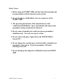
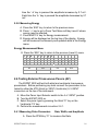
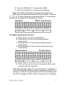
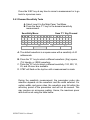
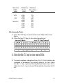
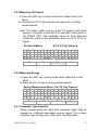
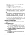
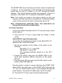
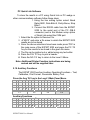
1
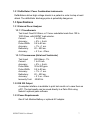
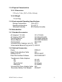
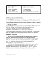
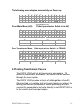
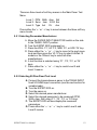
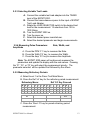
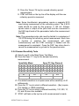
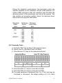
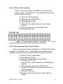
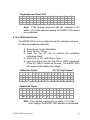
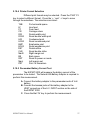
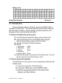
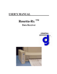
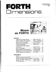
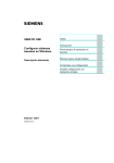
EXPMT 2000
External Pacemaker Analyzer
Operating Manual
110 Toledo Street
Farmingdale, NY 11735
Phone: 631-531-0100
Fax: 631-531-0101
www.netech.org
EXPMT 2000 User Manual
Copyright
Copyright © 2003 by Netech Corporation. All rights reserved. No part of this publication
may be reproduced or transmitted in any form other than for the purchaser’s personal use
without written permission from Netech Corporation.
Quality Assurance
Netech is ISO 9001-2000 Registered. This instrument was thoroughly tested and inspected
according to Netech’s ISO 9001-2000 quality standards and test procedures and found to
meet those specifications when it was shipped from the factory.
Warranty
Netech warrants the EXPMT 2000 against defects in materials and workmanship for one year
from the date of original purchase. The standard warranty is extended for a second year if the
instrument is returned to Netech for its recommended annual recalibration.
During the warranty period, we will repair or, at our option, replace at no charge a product
that proves to be defective, provided you return the product shipping prepaid to Netech
Corporation. This warranty does not apply if the product has been damaged by accident or
misuse or as the result of service or modification by other than Netech Corporation, or if its
serial number is defaced or removed.
Netech reserves the right to discontinue the EXPMT 2000 at any time, and change its
specifications, price, or design without notice and without incurring any obligation. Netech
guarantees availability of service parts for 5 years after the manufacture of the unit is
discontinued.
The warranty is void if you elect to have the unit serviced and / or calibrated by someone
other than Netech.
The purchaser assumes all liability for any damages or bodily injury that may result from the
use or misuse of the unit by the purchaser, his employees, agents, or customers. In no event
shall Netech Corporation be liable for consequential damages
Trademarks
Netech and EXPMT 2000 are trademarks of Netech Corporation. Any other trademark names
used in this manual are only for editorial purposes and the benefit of the respective trademark
owner with no intention of improperly using that trademark.
EXPMT 2000 User Manual
2
Table of Contents
1. General Overview
1.1
1.2
1.3
1.4
Introduction
-----------------------------------------Safety Considerations -----------------------------------Specifications -----------------------------------------Accessories
------------------------------------------
06
06
07
08
2. Operating Instructions
2.1
2.2
2.3
2.4
2.5
Getting Started ------------------------------------------ 09
Instrument Familiarity ----------------------------------- 09
Power Up and Initialization ---------------------------- 10
Menu Structure -------------------------------------------- 10
Testing Transthoracic Pacers -------------------------- 11
2.5.1 Selecting Pacer Manufacturer ----------------- 12
2.5.2 Selecting 50 Ohm Test Load ------------------ 12
2.5.3 Selecting Variable Test Loads ---------------- 13
2.5.4 Measuring Pulse Parameters ------------------ 13
2.5.5 Measuring Refractory Periods ---------------- 13
2.5.6 Demand Sensitivity Tests ---------------------- 14
2.5.7 Immunity Tests ---------------------------------- 15
2.5.8 Measuring Energy -------------------------------- 16
2.6 Testing External Transvenous Pacers (AV) -------- 16
2.6.1 Measuring Pulse Parameters ---------------- 16
2.6.2 Measuring Refractory Periods --------------- 17
2.6.3 Demand Sensitivity Tests -------------------- 18
2.6.4 Immunity Tests ----------------------------------- 19
2.6.5 Measuring AV Interval ------------------------ 20
2.6.6 Measuring Energy ------------------------------ 20
2.6.7 Pacemaker Type Selection ------------------- 20
2.7 Printing Pacer Measurements ------------------------ 21
2.7.1 Printing Without a Header --------------------- 21
2.7.2 Printing With a Header ------------------------- 21
2.8 Automatic Pacer Testing --------------------------------- 22
2.9 Printer Functions ----------------------------------------- 23
2.10 Auxiliary Functions -------------------------------------- 24
2.10.1 AV Pacer Test Function -----------------------25
EXPMT 2000 User Manual
3
2.10.2 Transcutaneous Pacer Test Function ----- 25
2.10.3 Calibration Check ------------------------------ 26
2.10.4 Printer Format Selection ---------------------- 27
2.10.5 Pacemaker Battery Current Test ---------- 27
3. Palm Pilot Interface
3.1 Introduction ------------------------------------------ 28
3.2 Netech PalmSoft Set Up Procedure ----------- 28
3.3 Receiving and Saving Data ---------------------- 28
4. Troubleshooting EXPMT 2000---------------------------
29
5. Appendix ------------------------------------------------------- 31
This Manual is provided to explain the operation of the EXPMT 2000,
External Pacemaker Analyzer.
It is intended for the biomedical engineering or clinical engineering
technician involved in the testing of external pacemakers.
The operator must be familiar with and follow the safety protocols
recommended by the device manufacturer.
EXPMT 2000 User Manual
4
Safety Notes:
1. Before using the EXPMT 2000 read the instruction manual and
become familiar with the functions and controls.
2. Do not discharge a defibrillator into any connectors of the
EXPMT 2000.
3. The operating instructions of the manufacturers of all
combination defibrillator / pacer instruments and transvenous
pacemakers being tested must be followed.
4. Do not connect transthoracic and transvenous pacemakers
simultaneously. Test only one type at a time.
5. Do not connect the pacer input before the EXPMT 2000 is
turned ON.
6. Do not change the variable pacer test load while a transthoracic
pacemaker is turned on. Turn the pacemaker off before
selecting a test load.
7. Do not discharge the output of a defibrillator into the EXPMT
2000.
EXPMT 2000 User Manual
5
GENERAL OVERVIEW
Section 1
1.1 Introduction
The EXPMT 2000 pacemaker analyzer is an advanced microprocessor
based test instrument designed to accurately measure the output
parameters of all external pacemakers, including both transthoracic and
transcutaneous devices.
The instrument is easy to use via the menu structure presented on
a large four line LCD display. Resulting measurements of the tests
performed are simultaneously shown on the LCD display.
The EXPMT 2000 is compact, lightweight, and rugged. It may be
operated with one 9 volt battery or with an optional AC adapter. A standard
RS232 serial port allows for printing and storage of results with optional
printers and PDAs.
1.1.1 Pacemaker Test Functions
The EXPMT 2000 makes several measurements of external
transthoracic, transvenous, and AV pacemakers.
1.1.1.1 Transthoracic Pacers
Test load: 50 Ohms or 12 user selectable loads from 100 to 1000 Ohms
using the plug in test load selector.
Measures: Peak current, pulse width, pulse rate, paced refractory period,
sensed refractory period, and pulse energy.
1.1.1.2 Transvenous Pacers
Measures: Peak current, pulse width, pulse rate, paced refractory period,
sensed refractory period, immunity test (50Hz/60 Hz), A/ V interval, and
pulse energy.
Measures: the current drain of the pacemaker using the optional adapter
(PN: 652-BATT).
1.2 Safety Considerations
Before using the EXPMT 2000, the operator must follow the safety
precautions listed in this manual.
EXPMT 2000 User Manual
6
1.2.1 Defibrillator / Pacer Combination Instruments
Defibrillators deliver high voltage shocks to a patient in order to stop a heart
attack. The defibrillator discharge pulse is potentially dangerous.
1.3 Specifications
1.3.1 External Pacer Analyzer
1.3.1.1 Transthoracic
Test Load: Fixed 50 Ohms, or 12 user selectable loads from 100 to
1000 Ohms, with EXPMT load selector.
Current:
1 to 200 mA.
Accuracy:
± 5% +. 5 mA
Pulse Width:
0.5 to 80 ms.
Accuracy:
± 1% +.1 ms.
Refractory:
20 – 500 ms.
Accuracy:
± 2 % or +10ms.
1.3.1.2 Transvenous (Atrial and Ventricular)
Test Load:
Current:
Accuracy:
Pulse Rate:
Pulse Width:
Accuracy:
Refractory:
Accuracy:
Immunity Test:
500 Ohms ± 1%.
1 to 25 mA.
± 5% +. 5 mA.
30 to 800 ppm.
0.5 to 80 ms.
± 1% +.1 ms.
20 – 500 ms.
± 2 % or +10ms.
50/60 Hz.
1.3.2 RS 232 Output
A computer interface is available to print test results or to save them on
a PC. The test results can be saved directly to a Palm Pilot using
Netech’s optional palm software.
1.3.3 Power Requirements
One 9 Volt Alkaline Battery or optional AC adapter.
EXPMT 2000 User Manual
7
1.3.4 Physical Characteristics
1.3.4.1 Dimensions
7.75 x 4 x 1.5 in. (19.7 x 10.2 x 3.8 cm)
1.3.4.2 Weight
1 lb (0.9 Kg)
1.3.5 Environmental Operating Specifications
Storage Temperature:
Operating temperature:
Maximum Humidity:
-25 to 50o C
15 to 40o C
95% Relative Humidity
1.4 Accessories
1.4.1 Standard Accessories
AC Adapter (110 VAC)
AC Adapter (220 VAC)
Operating Manual
Service Manual
Carrying Case
Universal Pacer Adapters (set of 2)
Unterminated Banana Plug (set of 2)
301 (110VAC)
301-220 (220 VAC)
950-USER-MANUAL
950-SERV-MANUAL
950-CASE
953
6383-02
1.4.2 Optional Accessories
Printer
Serial Printer Interface Cable
Software for PC
Palm Pilot Interface Software
DPM 441
903
650-PC-SOFT
650-PALM-SOFT
Transthoracic Cable Adapters:
HP
Zoll
PhysioControl
Marquette
Universal A/V Pacer Adapter Cable
Pacemaker Battery Test Adapter
951-HP
951-Zoll
951-Physio
951-MARQ
652
652-BATT
EXPMT 2000 User Manual
8
OPERATING INSTRUCTIONS
Section 2
2.1 Getting Started
Before unpacking the EXPMT 2000 inspect the shipping box for any visual
damage. If damage is found, do not unpack the unit and immediately notify
the shipping carrier.
If no damage is found to the shipping box, open the box and perform a visual
inspection of the EXPMT 2000. If any damage to the unit is observed please
contact Netech Customer Service.
The Netech warranty statement is listed in the warranty section of this
manual. When shipping an instrument to Netech for repair or calibration
make sure that the instrument is properly packed. A completed Service
Return Form must be included with the returned instrument to ensure the
timely repair and return of your instrument. The Service Return Form may
be obtained at our web site www.GoNetech.com or from the Netech
Customer Service Department.
2.2 Instrument Familiarity
Before proceeding to use the EXPMT 2000 make sure you read this manual
and become familiar with the functions, the controls, and the menu
operation.
EXPMT 2000
5
10
6
4
7
8
3
9
2
EXPMT 2000 User Manual
1
EXPMT LOAD
SELECTOR
9
1.
2.
3.
4.
5.
On / Off Switch
Serial Port
Five ECG Leads
LCD Display
Transvenous Inputs
6. Pacer Input Selector
7. Trancutaneous Inputs
8. Function Keys
9. DC Power Input
10. Transcutaneous Load Selector.
2.3 Power Up and Initialization
The EXPMT 2000 is battery powered. The power On / Off switch is located
on the right hand side of the instrument. When the instrument is turned on,
the model and the software revision level are displayed for about 5 seconds.
2.3.1 RS 232 Setup
The EXPMT 2000 can be connected to a printer / PC or a Palm Pilot via the
RS 232C SERIAL PORT located on the side of the instrument.
The default settings for the serial communication are:
Baud Rate = 9600, Data Bits = 8, Parity = None, Stop Bit = 1
These settings must be the same for the PC or the Printer. To retrieve the
data into a Palm Pilot use the optional interface cable for the Palm Pilot.
2.4 Menu Structure
The EXPMT 2000 is easily operated via a menu system utilizing an
eight key keypad located on the front of the instrument below the
display. Menus appear on the display above the four keys labeled ‘F1’,
‘F2’, ‘F3’, and ‘F4’. The four lower keys are labeled ‘←’, ‘ESC’, ‘PRN’
and ‘→’. Follow the instructions on the display and press the
appropriate key to use the instrument .
The ‘ESC’ key will change the display to the previous menu, and in
some situations it will confirm the menu selection. The ‘PRN’ key
activates an optional printer. The arrow keys, ‘←’ and ‘→’, move the
display forward or backward within a group of possible selections.
EXPMT 2000 User Manual
10
The following menu displays momentarily on Power up:
V
E
X
P
M T
e
r
s
i
o
2
n
0
0
0
X
.
R
X
*
* Current Software Version
Pacer Main Menu (A/V):
S
A
(If the Input selector Switch is in A/V)
e
P
l
r
e
e
c
s
t
s
t
r
i
a
l
F1
P
F
a
1
c
F2
e
o
r
V
e
T
y
F
p
4
e
n
t
r
i
F3
F4
Pacer Transthoracic Menu: (If the Input selector Switch is in TRANS)
<
Z
X
S
O
T
e
L
h
l
P
L
F1
o
e
R
r
c
N
H
a
t
=
P
c
H
i
m
e
M
F2
c
a
a
D
n
d
E
F3
T
u
e
y
f
r
L
p
e
I
F
>
E
F4
2.5 Testing Transthoracic Pacers
The EXPMT 2000 will test all transthoracic pacemakers. The
brand of transthoracic pacemaker to be tested must be selected
through the menu system.
The EXPMT 2000 provides a choice of utilizing either a fixed 50
Ohm test load or a variable test load (using the plug in adapter) for
testing transthoracic pacemakers. Before performing any tests
connect the pacemaker to be tested directly to the EXPMT 2000 or
to the variable test load input adapter.
EXPMT 2000 User Manual
11
There are three levels of soft key menus in the Main Pacer Test
Menu.
Level 1: PPM Wdth Amp Ref
Level 2: Sens Imm AV-D Enr
Level 3: Type Aut
Pri
Aux
Press either the ‘←’ or ‘→’ key to move between the three soft key
menu Levels.
2.5.1 Selecting Pacemaker Manufacturer
A. Move the PACER INPUT SELECTOR switch on the side
to the TRANS. INPUT position.
B. Turn the EXPMT 2000 instrument on.
C. Press the ZOLL ‘F1’, HP ‘F2’, MDE ‘F3’, or LIFE ‘F4’ key.
D. Press either the ‘ ←’ or ‘ →’ key to move to the next menu
level and then press the ‘LF-12’ key to select LifePak 12
models or the ‘Others’ key to select all other
manufacturers.
E. A test function is selected using ‘F1’, ‘F2’, ‘F3’, or ‘F4’
keys.
F. Press either the ‘ ←’ or ‘ →’ key to reach Level 2 and
Level 3 menus.
2.5.2 Selecting 50 Ohm Fixed Test Load
A. Connect the transcutaneous pacer to the TRANS INPUT
fixed 50 OHMS input connectors (see the next section for
variable loads).
B. Turn the EXPMT 2000 on.
C. Turn the pacer on.
D. Select the desired pacer manufacturer.
E. Select the desired parameter to be measured (PPM,
Wdth, Amp, Ref) using ‘F1’, ‘F2’, ‘F3’, or ‘F4’ keys.
F. The EXPMT 2000 will now display the measured
parameters.
G. Press either the ‘ ←’ or ‘ →’ key to reach Level 2 and
Level 3 menus.
EXPMT 2000 User Manual
12
2.5.3 Selecting Variable Test Loads
A. Connect the variable test load adapter into the TRANS
input of the EXPMT 2000.
B. Connect the transcutaneous pacer to the input of EXPMT
Test Load Adapter.
C. Rotate the LOAD SELECTOR switch to the desired test
load for the measurement. 12 selections from 100 to
1000 Ohms.
D. Turn the EXPMT 2000 on.
E. Turn the pacer on.
F. Select the desired pacer manufacturer.
G. Select the desired parameter and begin measurements.
2.5.4 Measuring Pulse Parameters:
Amplitude
Rate, Width, and
A. Press the PPM ‘F1’ key to measure the Rate.
B. Press the Wdth ‘F2’ key to measure the Width.
C. Press the Amp ‘F3’ key to measure the Amplitude.
Note: The EXPMT 2000 pacer will continuously measure the
parameters and update the display with the new values. Pressing
the ‘F1’,‘F2’, or ‘F3’ key will select the measurement priority. The
parameter selected will be updated first followed by the others.
2.5.5 Measuring Refractory Periods
A. Select Level 1 in the Pacer Test Main Menu.
B. Press the Ref ‘L4’ key for the refractory period measurement.
Refractory Menu:
R e
f
r
P
c
e
a
F1
a
c
Ref ‘F4’ Key Pressed
t
o
r
y
T
i
m e
S
e
n
s
e
F4
C. Press the ‘Pace’ F1 key for paced refractory period
measurement.
EXPMT 2000 User Manual
13
D. Press the ‘Sense’ F4 key for sensed refractory period
measurement.
E. STBY will flash on the top line of the display until the new
refractory period is measured.
Note: Some transthoracic pacemakers require a separate ECG
input during measurement of the refractory period. The 5 ECG
leads should be used for this purpose. A 100 mV, 40msec
square wave is output at the jacks and must be connected to
the EKG input leads of the pacemaker before the measurement
is made.
Note: The pacemaker pulse rate must be limited to a maximum of
180 PPM during the refractory period measurement. Each time
a function is selected the measurement will start
instantaneously and the STBY message is flashed until the
measurement is completed. Press the ‘ESC’ key at any time to
cancel the measurement or go back to the previous menu.
2.5.6 Demand Sensitivity Tests
A. Select Level 2 in the Main Pacer Test Menu.
B. Press the Sens ‘F1’ key for the demand sensitivity
measurement.
Sensitivity Menu:
S
e
n
S
q
r
s
F1
t
Sens ‘F1’ Key Pressed
v
t
y
4
0
m S
F2
=
S
T
F3
B
Y
F4
C. The default waveform is a square wave with a sensitivity of 40
milliseconds.
D. Press the ‘F1’ key to select a different waveform - (Sqr) square,
(Tri) triangle, or (SSQ) waveform.
E. Press the ‘F2’ key to select a different sensitivity. 100, 200, 10,
25, and 40 msec are available.
F. ‘STBY’ will flash on the top line until a measurement is made.
EXPMT 2000 User Manual
14
During the sensitivity measurement, the pacemaker pulse rate
selection depends on the waveform and the width selected. For
certain widths and pacer rates, the waveform may fall within the
refractory period of the pacemaker and will not be sensed. This
may produce an erroneous reading. Hence, the maximum pacer
rate must be set using the table below.
Waveform
Width
msec
Refractory Maximum
Period
Pacer Rate
msec
ppm
200
<300
<400
<300
<400
<250
<300
<350
<400
100
40/25/10
110
90
140
110
180
170
140
110
2.5.7 Immunity Tests
A. Press the ‘ESC’ key to return to the previous menu.
B. Select Level 2 in the Main Pacer Test Menu.
C. Press the Imm ‘F2’ key for the noise immunity test.
Immunity Menu:
6
N
o
i
0
H
z
F1
s
Imm ‘F2’ Key Pressed
e
I
F2
m m u
F3
n
i
t
y
5
0
H
z
F4
D. Press the 60Hz ‘F1’ key for a sine wave of 60Hz
E. Press the 50Hz ‘F4’ key for a sine wave of 50Hz.
G. The peak amplitude is displayed from 0 to 10 mV and may be
increased or decreased. The default setting is 5.7 mV. Each
EXPMT 2000 User Manual
15
time the ‘Æ’ key is pressed the amplitude increases by 0.7 mV.
Each time the ‘Å’ key is pressed the amplitude decreases by 0.7
mV.
2.5.8 Measuring Energy
A. Press the ‘ESC’ key to return to the previous menu.
B. Press ‘→’ key to go to Pacer Test Menu soft key Level 2 where
energy may be selected.
C. Press ENR ‘F4’ key for Energy measurement.
D. Energy will be displayed on the top line of the display. Energy
will be measured continuously and updated while in the Energy
menu.
Energy Measurement Menu
E. Press the ‘ESC’ key to return to the previous (Level 2) menu.
T
r
n
S
e
n
E
s
F1
n
r
g
I
m m
F2
=
A
V
F3
D
E
n
r
F4
2.6 Testing External Transvenous Pacers (AV)
The EXPMT 2000 will test both atrial and ventricular transvenous
pacemakers. Before performing any tests connect the pacemaker to be
tested to either the ATR (Atrial) or VENT (Ventricular) A-V INPUT
connectors on the top of the instrument.
A. Move the Pacer Input Selector switch to the A.V. INPUT position.
B. Turn the EXPMT 2000 on.
C. Select the pacer type by pressing the Atrial ‘F1’ key or the
Ventricular ‘F2’ key.
D. Perform the measurements in section 2.6.1.
2.6.1 Measuring Pulse Parameters
Rate, Width, and Amplitude
A. Press the PPM Key ‘F1’ to measure the Rate.
EXPMT 2000 User Manual
16
B. Press the Wdth Key ‘F2’ to measure the Width.
C. Press the Amp Key ‘F3’ to measure the Amplitude.
Note: The EXPMT 2000 pacer will continuously measure the
parameters and update the display with the new values. Press the
‘F1’, ‘F2’, or ‘F3’ key to select the measurement priority. The parameter
selected will be updated first followed by the others.
Rate Menu:
A
A
A
P
t
t
t
P
r
r
r
M
PPM ‘F1’ Key Pressed
R
W
A
W
F1
a
d
m
d
t
t
p
t
e
h
l
h
=
=
=
A
F2
m p
R
F3
e
f
F4
2.6.2 Measuring Refractory Periods
A. Select Level 1 in Pacer Test Main Menu.
B. Press the Ref ‘L4’ key for the refractory period
measurement.
C. Press the Pace ‘F1’ key for paced refractory period
measurement.
D. Press the Sense ‘F4’ key for sensed refractory period
measurement.
Refractory Menu:
R
e
f
r
P
a
c
e
F1
a
c
F2
‘F4’ Key Pressed
t
o
r
y
F3
T
i
m
e
S
e
n
s
e
F4
E. STBY will flash on the top line of the display until the new
refractory period is measured.
Note: The pacemaker pulse rate must be limited to a maximum of
180 PPM during the refractory period measurement. Each time a
function is selected the measurement will start immediately and
the STBY message will flash until the measurement is completed.
EXPMT 2000 User Manual
17
Press the ‘ESC’ key at any time to cancel a measurement or to go
back to a previous menu.
2.6.3 Demand Sensitivity Tests
A. Select Level 2 in the Main Pacer Test Menu.
B. Press the Sens ‘F1’ key for the demand sensitivity
measurement.
Sensitivity Menu:
S
e
n
S
q
r
s
F1
t
Sens ‘F1’ Key Pressed
v
t
y
4
0
m S
F2
=
S
T
F3
B
Y
F4
A. The default waveform is a square wave with a sensitivity of 40
milliseconds.
B. Press the ‘F1’ key to select a different waveform: (Sqr) square,
(Tri) triangle, or (SSQ) waveform.
C. Press the ‘F2’ key to select a different sensitivity: 100, 200, 10,
25, and 40 msec are available.
D. STBY will flash on the top line until a measurement is made.
During the sensitivity measurement, the pacemaker pulse rate
selection depends on the waveform and the width selected. For
certain widths and pacer rates, the waveform may fall within the
refractory period of the pacemaker and will not be sensed. This
may produce an erroneous reading. Hence, the maximum pacer
rate must be set using the table below.
EXPMT 2000 User Manual
18
Waveform
Width
msec
Refractory Maximum
Period
Pacer Rate
msec
ppm
200
<300
<400
<300
<400
<250
<300
<350
<400
100
40/25/10
110
90
140
110
180
170
140
110
2.6.4 Immunity Tests
A. Press the ‘ESC’ key to return to the Level 2 Main Pacer Test
Menu.
B. Press the Imm ‘F2’ key for the noise immunity test.
Immunity Menu:
6
N
o
i
0
H
z
F1
s
Imm ‘F2’ Key Pressed
e
I
F2
m m u
F3
n
i
t
y
5
0
H
z
F4
C. Press the 60Hz ‘F1’ key for a sine wave of 60Hz
D. Press the 50Hz ‘F4’ key for a sine wave of 50Hz.
E. The peak amplitude is displayed from 0 to 101.9 mV and may be
increased or decreased. The default setting is 54.3 mV. Each
time the ‘Æ’ key is pressed the amplitude increases by 6.8 mV.
Each time the ‘Å’ key is pressed the amplitude decreases by 6.8
mV.
EXPMT 2000 User Manual
19
2.6.5 Measuring AV Interval
A. Press the ‘ESC’ key to return to the Level 2 Main Pacer Test
Menu.
B. Press the AV-D ‘F3’ key from the main menu for A-V Delay
measurements.
Note: The select switch must be in the A-V position and inputs
must be connected to both the ATR and VENT input jacks on
the EXPMT 2000. The amplitude values for both atrial and
ventricular output on the pacemaker must be set to 0.1mA or
higher.
AV Interval Menu:
A V
S
e
D
n
e
s
AV-D ‘F3’ Key Pressed
l
a
I
m m
F1
y
=
A
V
D
E
F3
F2
n
r
F4
2.6.6 Measuring Energy
A. Press the ‘ESC’ key to return to the Level 2 Main Pacer Test
Menu.
B. Press the Enr ‘F4’ key for Energy measurements.
Energy Measurement Menu: Enr ‘F4’ Key Pressed
A
t
r
S
e
n
E
s
F1
n
r
g
I
m m
F2
=
A
V
F3
D
E
n
r
F4
2.6.7 Pacemaker Type Selection
During measurements the atrial and ventricular inputs may be
changed or a different pacemaker may be tested. This is done
using the ‘Type’ function key in the Pacer Test Main Menu.
EXPMT 2000 User Manual
20
A. Press the ‘Esc’ Key to back up one menu.
B. Press the ‘←’ or ‘→’ to move to Level 2 Main Pacer Menu.
C. Press the Type ‘F1’ Key.
D. Press the Atr ‘F1’ or Vtr ‘F2’ to make a change.
E. Press the TrX ‘F4’ Key to select Transthoracic and then
select the pacer manufacturer.
The pacemaker type select switch should be in the position
marked ‘A-V INPUT’, to make atrial and ventricular measurements
of invasive pacemakers, and in the position marked ‘TRANS.
INPUT’ to make measurements of transthroracic pacemakers.
Note:
1. If during an Atrial or Ventricular measurement the pacer input
selector switch is changed from ‘AV’ to ‘Trans’ then any
function key stroke will prompt the user to select the
appropriate transcutaneous pacemaker by displaying the
available choices. The load will be changed to 50 ohms. On
selection of a particular pacemaker, the display reverts back to
the previous menu. Moving the switch position back to A-V
would go back to Ventricular measurements (500 ohms load)
and the display will be updated on any function key.
2.8 Printing Pacer Measurements
Pacer test measurement results may be printed with or without a
header.
2.8.1 Printing Without a Header
A. Press the ‘PRN’ key on the Keypad to print the measured
test data from the EXPMT 2000 in the Pacer Test mode.
B. The EXPMT 2000 will send data to the printer port each
time the display updates with current parameter
measurements.
C. Press the ‘PRN’ key again to stop the continuous printing
of parameter measurements.
2.8.2 Printing a Header
A. Press the ‘ESC’ key to return to the Level 2 Pacer Menu
B. Press the Pri ‘F3’ key.
EXPMT 2000 User Manual
21
C. Press either the Prtr ‘F1’ key or the PrH ‘F3’ key to print
the header.
NETECH
PACEMAKER TESTER
EXPMT 2000
Date:__________________
Control No. ____________
Model No. _____________
Serial No. _____________
Manf. _________________
Hospital _______________
BMET_________________
Remarks
_______________
Pass_______ Fail _______
VENTRICULAR TESTS
ATRIAL TESTS
TRANSTHORACIC TESTS
D. Return to the Pacer measurement program to perform
tests.
2.9 Automatic Pacer Testing
In the Automatic Pacer Testing Mode, measurements are performed
semi-automatically on seven parameters: pacer rate, pacer width,
pacer amplitude, pacing refractory interval, sensing refractory
interval, sensitivity, and A-V delay. The pacer width measurement is
combined with the PPM measurement.
For each parameter being measured, 10 different test values are
preprogrammed. The user has the option of running all 10 of the
tests using default values, running one or more tests with user
selected values, or eliminating any of the tests.
User modified values, may be saved for use in subsequent tests as
long as the EXPMT 2000 is not turned off. The user can leave the
modified value unsaved so that the original default values will be
output during subsequent tests. The test sequence continues until all
of the parameters are tested.
EXPMT 2000 User Manual
22
The EXPMT 2000 stores the measured values of each test performed
in memory. At the completion of the automatic test sequence, the
results may be sent to a printer or to a PC through the RS232
interface. The set and measured values are compared. If there is a
deviation of more than 10%, a comment to that effect is printed.
Note: Test results are saved in the memory during an auto test
sequence until the instrument is switched off. This permits multiple
copies of the results to be made on the printers and /or PC.
Note: Comprehensive Automatic Pacer Test instructions are
being revised and will be supplied later.
2.9 Printer Functions
In the Level 3 Main Pacer Menu the Pri ‘F3’ key will access various
printer options.
A. Press the Prtr ‘F1’ key to select either the Citizen or Seiko
printer.
Seiko DPU411 type II thermal printer
To print the test measurement results on the Seiko DPU 411
thermal printer, follow these steps:
1 Set the dip switches at the bottom of the printer to the
following:
Dip switch 1: 4, 5, 7, and 8 ON
Dip switch 2: 1 and 2 ON
The remaining switches should be in the OFF
position.
2 Connect the printer cable from the EXPMT 2000 to the
serial input connector (DB-25 connector) of the printer
DPU 411.
3 Turn the printer ON and press the ON LINE switch on the
printer (online LED lights up).
Now the printer is ready to receive data from the EXPMT 2000.
Select PRI in the main menu of the EXPMT 2000 and press the
‘F1’ key. The ‘Select Printer’ menu is now displayed showing the
printer options. Now select F4 (Seiko) key to print the results.
B. Press the PC ‘F2’ key to save the test measurements.
EXPMT 2000 User Manual
23
PC Quick Link Software
To store the results in a PC using Quick Link or PC wedge or
other communications software follow these steps:
1. Using the line setting option select: Baud
Rate=9600, Data Bits=8, Parity=None, Stop
Bits=1.
2. Connect the RS232 cable from the EXPMT
2000 to the serial port of the PC (DB-9
connector) and in the Modem setup option
of Quick Link select the COM port.
1 Select the file option to Receive File.
2 Æ”ASCII” and enter a file name to which the EXPMT 2000
results are to be stored.
3 Once the above selections have been made press ‘PRI’ in
the main menu of the EXPMT 2000 and press the PC ‘F2
‘key for the results to be stored in the given file name.
4 The file can be printed out or edited using any text editor.
5 Press the PrH ‘F3’ key to print a header.
6 Press the NO ‘F4’ key to return to the Level 3 Menu.
Note: Additional Printer Function instructions are being
revised and will be supplied later.
2.10 Auxiliary Functions
The EXPMT 2000 has four Auxiliary Operating Functions – Test,
Calibration, Print Format, Pacemaker Battery Test.
Press the Aux ‘F4’ key in the Level 3 Main Pacer Menu.
< - P a c e r
T e s t - >
T Y
p e
A u t
F1
P r
F2
i
A u x
F3
F4
Auxiliary Functions
A
T
s
t
u
x
C
F
a
EXPMT 2000 User Manual
l
u
n
c
t
i
P
r
F
S
o
n
s
B
a
t
24
2.10.1 AV Pacer Test Function
In the AV Pacer Test Mode, the EXPMT 2000 inputs a DC
output voltage of 100 millivolts ± 5 and displays both the input
and the measured values.
A.
B.
C.
D.
E.
Select the AV Pacer Mode.
Select the Level 2 Main Menu.
Press the Aux ‘F4’ key.
Press the Tst ‘F1’ key.
Place the Pacer Select Switch in the AV Input
position.
F. Disconnect the input to the EXPMT 2000.
G. Press the ‘ESC’ key.
AV Pacer Test
S
e
l
e
c
t
e
d
M
e
a
s
u
r
e
d
1
9
9
.
8
m
v
0
0
.
1
m
v
Note: If the measured reading is not within ± 5 % of the
selected reading the EXPMT 2000 should be recalibrated.
2.10.2 Transcutaneous Pacer Test Function
In the Transcutaneous Pacer Test Mode, the EXPMT 2000 outputs
a voltage of 10 millivolts ± 0.5. This voltage may be checked with a
voltmeter connected to the Vent jacks of the A-V Intput connectors.
B. Select the Level 2 Main Menu.
C. Press the Aux ‘F4’ key.
D. Select the Transcutaneous Pacer Mode.
H. Press the Tst ‘F1’ key.
I. Place the Pacer Select Switch in the TRANS Input
position.
J. Disconnect the input to the EXPMT 2000.
K. Connect the voltmeter to the Vent jacks of the A-V
Intput connectors.
L. Press the ‘ESC’ key.
M. Read the measurement in mV on the voltmeter
display.
EXPMT 2000 User Manual
25
Transcutaneous Pacer Test
S
e
l
e
c
t
e
d
1
0
.
0
m
V
Note: If the reading measured with the voltmeter is not
within ± 5% of the selected reading the EXPMT 2000 should
be recalibrated.
2.10.3 Calibration Check
The EXPMT 2000 can be configured as a DC voltmeter and used
to check the amplitude calibration.
A. Select Level 2 in the Main Menu.
B. Press the Aux ‘F4’key
C. Press the Cal ‘F2’ key to perform the amplitude
calibration check.
D. Select ‘Atr’ or ‘Vtr’ as the Pacer Type.
E. Input less than 2 volts into the ATR or VENT connectors
of the A.V. INPUT section on the side. The EXPMT 2000
will measure and display this voltage.
Calibration Check
C
F
e
e
a
d
Cal ‘F2’ Key Pressed
l
C
<
2
h
e
c
k
V
o
l
t
s
D
C
Calibration Check
M
e
a
C
a
l
s
u
r
C
e
d
h
e
c
k
1
.
8
V
Note: If the reading measured is not within ± 5% of the
Input voltage, the EXPMT 2000 should be recalibrated.
EXPMT 2000 User Manual
26
2.10.4 Printer Format Selection
Different print formats may be selected. Press the ‘PrSF’ F3
key to select a different format. Press the ‘←’ and ‘→’ keys to move
through the selections. The selections are listed :
TAB
LF
FF
CR
DW
DCLR
HW
HCLR
EMP
ECLR
DST
CLR
MarR
BS
RST
MarL
PRT
Fix horizontal space
Line feed
Form feed
Carriage return
Double width print
Reset double width print
Condensed print
Reset condensed print
Emphasize print
Reset emphasize print
Double strike
Reset double strike
Right margin set
Back space
Reset to power on mode
Left margin set
Print 16 characters
2.10.5 Pacemaker Battery Current Test
The EXPMT 2000 will measure the battery current of the
pacemaker to be tested. The Netech 652-Battery Adapter is required to
perform this measurement.
A. Connect the battery adapter to the pacemaker and a 9 Volt
battery.
B. Connect the banana jacks of the battery adapter to the
VENT connectors of the A.V. INPUT section on the side of
the EXPMT 2000.
C. Press the Bat ‘F4’ key to perform the measurement.
EXPMT 2000 User Manual
27
Battery Test
B
a
t
t
e
r
y
M
e
a
s
u
r
e
C
u
r
r
e
n
t
0
.
0
m
A
Palm Pilot Interface
Section 3
3.11 Introduction
Optional Netech software, PalmSoft, allows the EXPMT 2000 to
Interface to a Palm Pilot. Test measurements may be downloaded into
the Palm Pilot for display, storage, editing, and later transfer to a PC.
Equipment files may be entered and edited.
3.12 Netech PalmSoft Set Up Procedure
D. Load the Netech PalmSoft software into the Palm Pilot.
E. Connect the Palm Pilot to the EXPMT 2000 using the
Netech serial interface cable, 650-Palm-Cable.
F. Activate the Netech PalmSoft software.
G. Set Up:
1. Baud rate:
9600
2. Data bits:
8 bit
3. Parity:
None
4. Stop bits:
1
5. Flow control: None
H. Enter the file name to be saved into the Palm Pilot. If no file
name is entered, the default name is “test”.
3.13 Receiving and Saving Data
The Palm Pilot is now ready to receive measurement data from the
EXPMT 2000.
A. Press the receive key of the Palm Pilot.
B. Press the ‘PRN’ key on the EXPMT 2000.
C. Edit the equipment profile on the Palm Pilot
display, see Fig A below.
EXPMT 2000 User Manual
28
NETECH
DEFIB TESTER
EXPMT 2000
Date:
Control No.
Model No.
Serial No.
Manf.
Hospital:
BMET:
Remarks:
Pass:
Fig A
Fail:
Energy set:
Energy: 103 Joules
Peak Voltage: 1739 Volts
Peak Current: 34 Amp
Fig B
D. Set the test values for the instrument to be tested,
see Fig B above.
E. Save the file.
F. The file is now available for printing or transferring
to a PC.
TROUBLESHOOTING
Section 5
5.1 Troubleshooting Chart
The following chart is provided for basic troubleshooting. Problems
other than those listed should be addressed to the Netech Technical
Service Department at 631-531-0100.
Description
On Power up the
Display is blank
EXPMT 2000 User Manual
Cause
The Battery Voltage
may be low or the
Action
Replace with new
battery or use AC
29
The display shows
non ASCI Characters
Low battery warning
EXPMT 2000 User Manual
display contrast is set
low
Memory corruption
Battery is low
adapter.
Turn Unit off and
then turn it On.
Replace battery
30
Appendix A
Section 6
This Page is left blank intentionally for future updates.
EXPMT 2000 User Manual
31