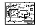
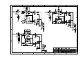
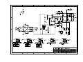
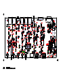
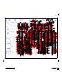
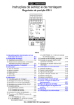
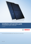
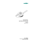
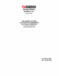
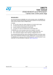
1
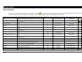
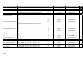
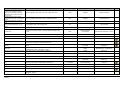
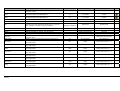
Analogue TDcontroller –S12
Service Manual
(rev AV1)
P.2
___________________________________________________________________________________________________
Declaration of conformity
This equipment has been tested and found to comply with the safety objectives and essential requirements of European (73/23/EEC and
89/336/EEC directives) and international Standards, by fulfilling the requirements of the following harmonized standards:
Electrical Safety (EU) : IEC 60065 (12/2001) Audio, video and similar electronic apparatus
Electrical Safety (US) : UL60065 Seventh Edition, dated June 30, 2003 category AZSQ, E241312.
Electrical Safety (CAN) : CSA-C22.2 N°60065:03 Edition, dated April 2003 category AZSQ7, E241312
Electrical Safety (Rest of the World) : CB test certificate DK-8371 based on IEC60065-2001 7nd ed. with all national deviations.
Radiated Emission (EU) : EN55103-1 (1996) Electromagnetic compatibility - Product family standard for audio, video, audiovisual and entertainment lighting control apparatus for professional use.
Audio Equipment
10CE
Radiated Emission (US) : FFC part15 class B
Radiated Emission (CAN) : This Class B digital apparatus complies with Canadian ICES-003.
RF Immunity (EU) : EN55103-2 (1996) Electromagnetic compatibility - Product family standard for audio, video, audio-visual and
entertainment lighting control apparatus for professional use.
Note: EMC conformance testing is based on the use of recommended cable types. The use of other cable types may degrade EMC
performances.
Information about products that generate electrical noise :
IMPORTANT SAFETY INSTRUCTIONS
1) Read these instructions.
2) Keep these instructions.
3) Heed all warnings.
4) Follow all instructions.
5) Do not use this apparatus near water.
6) Clean only with dry cloth.
7) Do not block any ventilation openings. Install in accordance with the
manufacturer’s instructions.
8) Do not install near any heat sources such as radiators, heat registers, stoves, or
other apparatus (including amplifiers) that produce heat.
9) Do not defeat the safety purpose of the polarized or grounding-type plug. A
polarized plug has two blades with one wider than the other. A grounding type plug
has two blades and a third grounding prong. The wide blade or the third prong are
provided for your safety. If the provided plug does not fit into your outlet, consult an
electrician for replacement of the obsolete outlet. (US market)
10) Protect the power cord from being walked on or pinched particularly at plugs,
convenience receptacles, and the point where they exit from the apparatus.
11) Only use attachments/accessories specified by the manufacturer.
13) Unplug this apparatus during lightning storms or when unused for long periods of
time.
14) Refer all servicing to qualified service personnel. Servicing is required when the
apparatus has been damaged in any way, such as power-supply cord or plug is
damaged, liquid has been spilled or objects have fallen into the apparatus, the
apparatus has been exposed to rain or moisture, does not operate normally, or has
been dropped.
NOTE: The United States Federal Communications Commission (in 47 CFR 15.105)
has specified that the following notice be brought to the attention of users of this
product:
This equipment has been tested and found to comply with the limits for a Class B
digital device, pursuant to Part 15 of the FCC Rules. These limits are designed to
provide reasonable protection against harmful interference in a residential installation.
This equipment generates, uses and can radiate radio frequency energy and, if not
installed and used in accordance with the instructions, may cause harmful interference
to radio communications. However, there is no guarantee that interference will not
occur in a particular installation. If this equipment does cause harmful interference to
radio or television reception, which can be determined by turning the equipment off
and on, the user is encouraged to try to correct the interference by one or more of the
following measures:
- Reorient or relocate the receiving antenna.
- Increase the separation between the equipment and receiver.
- Connect the equipment into an outlet on a circuit different from that to which the
receiver is connected.
- Consult the dealer or an experienced radio/TV technician for help.
The user may find the following booklet, prepared by the Federal Communications
Commission, helpful: How to identify and Resolve Radio/TV Interference Problems.
This booklet is available from the U.S. Government Printing Office, Washington,
D.C. 20402, Stock No. 004-000-00345-4. Use of a shielded cable is required to
comply within Class B limits of Part 15 of FCC Rules. Pursuant to Part 15.21 of the
FCC Rules, any changes or modifications to this equipment not expressly approved by
NEXO S.A. may cause, harmful interference and void the FCC authorization to
operate this equipment.
CAUTION
RISK OF ELECTRIC SHOCK
DO NOT OPEN
The lightning flash with arrowhead
symbol, within an equilateral triangle
is intended to alert the user to the
presence of uninsulated “dangerous
voltage” within the product's
enclosure that may be of sufficient
magnitude to constitute a risk of
electric shock to persons.
WARNING: To reduce the risk of fire or electric shock,
do not expose this apparatus to rain or moisture.
To avoid electrical shock, do not remove covers.
Dangerous voltages exist inside.
Refer all servicing to qualified personnel only.
The exclamation point within an
equilateral triangle is intended to
alert the user to the presence of
important operating and
maintenance (servicing) instructions
in the literature accompanying
the appliance.
WARNING ! This appliance is a CLASS 1 apparatus and must be earthed.
The green and yellow wire of the mains cord must always be connected to an installation safety earth or ground. The earth is essential for
personal safety as well as the correct operation of the system, and is internally connected to all exposed metal surfaces. Additional
recommendation for interconnection to other equipment can be found in the FOREWORD at the beginning of this manual
Analogue TDcontroller S12 rev AV1
20Dec07
P.3
___________________________________________________________________________________________________
Table of content
IMPORTANT SAFETY INSTRUCTIONS .........................................................................................................................2
FOREWORD ..........................................................................................................................................................................4
SAFETY INSTRUCTION .....................................................................................................................................................4
HISTORY................................................................................................................................................................................5
MECHANICAL ISSUES .......................................................................................................................................................6
REMOVING THE TOP PANEL .....................................................................................................................................................6
REMOVING THE PCB ...............................................................................................................................................................6
TROUBLE SHOOTING ........................................................................................................................................................7
LINEAR SECTION ......................................................................................................................................................................7
SERVO CONTROL SECTION .....................................................................................................................................................16
PART LIST REV AV1 .........................................................................................................................................................19
CRITICAL COMPONENTS ........................................................................................................................................................19
SCHEMATICS .....................................................................................................................................................................29
Analogue TDcontroller S12 rev AV1
20Dec07
Foreword
CAUTION !
This servicing instruction is for use by qualified service personnel only. To reduce the risk of electric shock
do not perform any servicing other than that contained in the operating instructions unless you are
qualified to do so.
Contact [email protected] for any information not contained in this manual.
Safety instruction
Mains Power
WARNING ! THIS APPLIANCE MUST BE EARTHED.
The green and yellow wire of the mains cord must always be connected to an installation safety earth or
ground. The earth is essential for personal safety as well as the correct installation of the system, and is
internally connected to all exposed metal surfaces. Any rack framework into which this unit may be
mounted is assumed to be connected to the same grounding circuit. (see also p.4)
NEXO TDcontrollers don’t provide a mean to switch off the unit from the front panel. As they are intended
to be rack mounted the back panel is not accessible during use. Therefore it is left to the user to provide a
disconnection mean readily operable.
Voltage setting
NEXO TDcontrollers use a switch mode power supply (SMPS). This SMPS accepts universal AC power
input voltages in the range 90V to 264V, and requires no manual adjustment for voltages in this range.
Mounting the TDcontroller in a rack (Grounding, shielding & safety issues)
The TDcontroller is intended for rack mounting. The only accessible part during use shall be the front
panel of the TDcontroller. Any space above or under the TDcontroller shall be obstructed with a blank
panel.
The rack is a free grounding and shielding structure and it provides extra shielding. Therefore, it is
desirable that the screws used to fix the TDcontroller in the frame or rack provide an electrical contact
between the chassis of the TDcontroller and the rack.
The primary reason for grounding is safety. Conformance to the applicable requirements of the authorities
having jurisdiction is, of course, mandatory. However, grounding also has an impact on electromagnetic
compatibility. From the EMC point of view, it is desirable to have a low impedance ground network, as a
current flowing in the ground network will then produce low voltage in the network. A low impedance
network can be obtained using a multipoint ground scheme, with as many closed ground loops as is
economically possible.
Fuse
The fuse provided in the unit will not blow during normal operation. If the fuse blows the TDcontroller has
malfunctioned. This fuse must only be changed by NEXO certified service personnel. In any case do not
replace the fuse with a non-certified NEXO fuse, as this will invalidate the NEXO warranty.
Analogue TDcontroller S12 rev AV1
20Dec07
History
Partlist
PCB ref
note
V1.0
TDMK3 1.3
initial
Analogue TDcontroller S12 rev AV1
20Dec07
S/N
Date
Mechanical issues
Most of the maintenance can be done without taking the PCB away. All test points are accessible on the
top layer of the PCB and allows a complete diagnostic. The bottom layer contains all discrete components
(diode, capacitor, resistors…)
Removing the top panel
To remove the top panel; unscrew the 4 screws circled in red in the above drawing (POZIDRIVE
screwdriver).
Removing the PCB
The remove the PCB; unscrew the 7 screws in blue square (POZIDRIVE screwdriver). The PCB must
then be pulled backward to free the fixation point at the front of the TDcontroller.
To pull the PCB back in place, first insert the front fixation in the front holes and push gently to align the
back screws in front of their holes. Pay attention that the guide light and push buttons of the front panel
are correctly aligned.
DO NOT FORGET TO PLACE THE STAR WASHER ON THE SCREW NEAR THE IEC SOCKET.
Analogue TDcontroller S12 rev AV1
20Dec07
Trouble shooting
This section displays the traces at each TDcontroller test-point. With a signal generator and an
oscilloscope one can easily check that the signal is approximately correct at each test-point. A deeper
(ans faster) analysis will require an AudioPrecison S1 with a switcher in order to perform the production
test. Contact the NEXO factory at [email protected] in order to receive instructions.
Linear section
The following traces are taken with the sense connector NOT connected. Both inputs fed with a 0dBV
(1Vrms) signal. Unless stated the configure button is released in Overlap mode, the back panel gain
switch is set in medium position (0dB) and the front sub potentiometer is fully turn right (maximum).
LT1-RT1 Input stage
+10
3
+7.5
2
+5
+2.5
+0
d
B
V
1
-2.5
700m
-5
500m
-7.5
400m
-10
300m
-12.5
200m
-15
-17.5
-20
20
100m
50
100
200
500
Hz
Analogue TDcontroller S12 rev AV1
20Dec07
1k
2k
5k
10k
20k
V
LT2-RT2 input gain
+10
3
+7.5
2
+5
+2.5
+0
d
B
V
1
-2.5
700m
-5
500m
-7.5
400m
-10
300m
V
-12.5
200m
-15
-17.5
-20
20
100m
50
100
200
500
1k
2k
5k
10k
20k
Hz
LT3-RT3 HPF EQ LPF + Protections
Go directly to testpoint 8 if testpoint 3 is fine. The second curve is for the configure font panel button in
crossover mode. (Red LED on)
+10
3
+7.5
2
+5
+2.5
+0
d
B
V
1
-2.5
700m
-5
500m
-7.5
400m
-10
300m
-12.5
200m
-15
-17.5
-20
20
100m
50
100
200
500
Hz
Analogue TDcontroller S12 rev AV1
20Dec07
1k
2k
5k
10k
20k
V
LT4-RT4 High pass filter Crossover
+10
3
+7.5
2
+5
+2.5
+0
d
B
V
1
-2.5
700m
-5
500m
-7.5
400m
-10
300m
V
-12.5
200m
-15
-17.5
-20
20
100m
50
100
200
500
1k
2k
5k
10k
20k
Hz
LT5-RT5 High pass filter Overlap
+10
3
+7.5
2
+5
+2.5
+0
d
B
V
1
-2.5
700m
-5
500m
-7.5
400m
-10
300m
-12.5
200m
-15
-17.5
-20
20
100m
50
100
200
500
Hz
Analogue TDcontroller S12 rev AV1
20Dec07
1k
2k
5k
10k
20k
V
LT6-RT6 HPF + EQ
+10
3
+7.5
2
+5
+2.5
+0
d
B
V
1
-2.5
700m
-5
500m
-7.5
400m
-10
300m
V
-12.5
200m
-15
-17.5
-20
20
100m
50
100
200
500
1k
2k
5k
10k
20k
Hz
LT7-RT7 HPF + EQ + LPF
+10
3
+7.5
2
+5
+2.5
+0
d
B
V
1
-2.5
700m
-5
500m
-7.5
400m
-10
300m
-12.5
200m
-15
-17.5
-20
20
100m
50
100
200
500
Hz
Analogue TDcontroller S12 rev AV1
20Dec07
1k
2k
5k
10k
20k
V
LT8-RT8 HPF EQ LPF + Protections + output gain
The curves correspond to the three gain of the back panel switch -6dB/0/+6dB
+10
3
2
+5
1
+0
-5
d
B
V
500m
-10
V
200m
-15
100m
-20
-25
40m
-30
20
50
100
200
500
1k
2k
5k
10k
20k
Hz
LT9-RT9 output pin3 // LT10-RT10 output pin 2
Symmetrical output stage: the two curve of testpoints 9 & 10 shall be within 0.5dB
+10
3
+7.5
2
+5
+2.5
+0
d
B
V
1
-2.5
700m
-5
500m
-7.5
400m
-10
300m
-12.5
200m
-15
-17.5
-20
20
100m
50
100
200
500
1k
Hz
T11 Sub summation
The Jumper ST1 must be set on PIN2-3, both inputs fed.
Analogue TDcontroller S12 rev AV1
20Dec07
2k
5k
10k
20k
V
+10
3
+7.5
2
+5
+2.5
+0
1
-2.5
d
B
V
700m
-5
500m
-7.5
400m
-10
300m
V
-12.5
200m
-15
-17.5
-20
20
50
100
200
500
1k
2k
5k
10k
20k
100m
Hz
T12 Sub HPF-EQ-LPF-channel Gain
Effect of the front panel potentiometer 12dB between min and max. (potentiometer has a tolerance of
20% that may cause some drift of nominal values of about 1dB.
+10
3
+7.5
2
+5
+2.5
+0
1
-2.5
d
B
V
700m
-5
500m
-7.5
400m
-10
300m
-12.5
200m
-15
-17.5
-20
20
100m
50
100
200
500
Hz
Analogue TDcontroller S12 rev AV1
20Dec07
1k
2k
5k
10k
20k
V
T13 Sub Low pass filter
+10
3
+7.5
2
+5
+2.5
+0
d
B
V
1
-2.5
700m
-5
500m
-7.5
400m
-10
300m
V
-12.5
200m
-15
-17.5
-20
20
100m
50
100
200
500
1k
2k
5k
10k
20k
Hz
T14 Sub LPF + HPF2nd ordrer
+10
3
+7.5
2
+5
+2.5
+0
d
B
V
1
-2.5
700m
-5
500m
-7.5
400m
-10
300m
-12.5
200m
-15
-17.5
-20
20
100m
50
100
200
500
Hz
Analogue TDcontroller S12 rev AV1
20Dec07
1k
2k
5k
10k
20k
V
T15 Sub LPF + HPF3rd ordrer
+10
3
+7.5
2
+5
+2.5
+0
d
B
V
1
-2.5
700m
-5
500m
-7.5
400m
-10
300m
V
-12.5
200m
-15
-17.5
-20
20
100m
50
100
200
500
1k
2k
5k
10k
20k
Hz
T16 Sub LPF + HPF3rd ordrer + EQ
+10
3
+7.5
2
+5
+2.5
+0
d
B
V
1
-2.5
700m
-5
500m
-7.5
400m
-10
300m
-12.5
200m
-15
-17.5
-20
20
100m
50
100
200
500
Hz
Analogue TDcontroller S12 rev AV1
20Dec07
1k
2k
5k
10k
20k
V
T17 Sub HPF-EQ-LPF-channel Gain + output gain
The curves correspond to the three gain of the back panel switch -6dB/0/+6dB
+0
1
-2.5
700m
-5
d
B
V
500m
-7.5
400m
-10
300m
-12.5
200m
-15
V
-17.5
-20
100m
-22.5
70m
-25
50m
-27.5
40m
-30
20
50
100
200
500
1k
2k
5k
10k
20k
Hz
T18 output pin3 // T19 output pin 2
Symmetrical output stage: the two curve of testpoints 18 & 19 shall be within 0.5dB
+10
3
+7.5
2
+5
+2.5
+0
1
-2.5
d
B
V
700m
-5
500m
-7.5
400m
-10
300m
-12.5
200m
-15
-17.5
-20
20
100m
50
100
200
500
Hz
Analogue TDcontroller S12 rev AV1
20Dec07
1k
2k
5k
10k
20k
V
Servo control section
For the following test point a 20Vrms signal is directly injected in the sense connector. Check the following
in case of protection failure. If the following traces are good and the problem persist it will be necessary to
run the production procedure.
LT20-RT20
+10
3
+7.5
2
+5
+2.5
+0
d
B
V
1
-2.5
700m
-5
500m
-7.5
400m
-10
300m
V
-12.5
200m
-15
-17.5
-20
20
100m
50
100
200
500
1k
2k
5k
10k
20k
Hz
LT21-RT21
+10
3
+7.5
2
+5
+2.5
+0
d
B
V
1
-2.5
700m
-5
500m
-7.5
400m
-10
300m
-12.5
200m
-15
-17.5
-20
20
100m
50
100
200
500
Hz
Analogue TDcontroller S12 rev AV1
20Dec07
1k
2k
5k
10k
20k
V
LT22-RT22
+10
3
+7.5
2
+5
+2.5
+0
d
B
V
1
-2.5
700m
-5
500m
-7.5
400m
-10
300m
V
-12.5
200m
-15
-17.5
-20
20
100m
50
100
200
500
1k
2k
5k
10k
20k
Hz
LT23-RT23-T24
Rectifier. Can’t be checked with a frequency response
T25
+10
3
+7.5
2
+5
+2.5
+0
d
B
V
1
-2.5
700m
-5
500m
-7.5
400m
-10
300m
-12.5
200m
-15
-17.5
-20
20
100m
50
100
200
500
Hz
Analogue TDcontroller S12 rev AV1
20Dec07
1k
2k
5k
10k
20k
V
T26
+10
3
+7.5
2
+5
+2.5
+0
d
B
V
1
-2.5
700m
-5
500m
-7.5
400m
-10
300m
-12.5
200m
-15
-17.5
-20
20
50
100
200
500
Hz
Analogue TDcontroller S12 rev AV1
20Dec07
1k
2k
5k
10k
20k
100m
V
Part list rev AV1
Critical components
Due to the UL and CB scheme certifications the components marked
shall never be changed with an equivalent part (unless stated in the list below). In case of failure,
the exact same type and reference shall be used. Failing to do so will void the warranty and the UL responsibility and certification.
DES
Description
BG1
Bridge rectifier, V(RRM)=800V, Vr(RMS)=560V, Io=2A, I(FSM)=65A
C202 C203
Ceramic Disk Capacitor, Safety, Class X1/Y2 440V/250V(AC), D12,
S4.5, p=7.5mm
C10 C20 C7 C28
Val
Manufacturer
Ref
UL
International rectifier
IRC2KBP08
-
2.2n
Vishay
WKO222*CPC*0K
Aluminium Electrolytic capacitor, tol=20% p=5mm, 63V, 2500h /
85deg
1u
BC components
037rsm serie
-
C190-191
Aluminium Electrolytic capacitor, tol=20% p=5mm, 100V, 2500h /
85deg
2.2u
BC components
222203738228
-
C192
Aluminium Electrolytic capacitor, tol=20% p=5mm, 100V, 2500h /
85deg
3.3u
BC components
037rsm serie
-
C187
Aluminium Electrolytic capacitor, tol=20% p=2.5mm, 50V, 2000h /
105deg diam: 5mm
4.7u
BC Components
222211651478
-
Aluminium Electrolytic capacitor, tol=20% p=5mm, 100V, 2500h /
85deg
4.7u
BC components
037rsm serie
-
C1-2 C5-6 C9 C22 C24 C31-32
Aluminium Electrolytic capacitor, tol=20% p=5mm, 63V, 2500h /
85deg
10u
BC components
037rsm serie
-
C185
Aluminium Electrolytic capacitor, tol=20% p=2.5mm, 25V, 2000h /
105deg diam: 5mm
47u
BC Components
222211656479
-
C14 C16 C18 C11 C26 C13
Aluminium Electrolytic capacitor, tol=20% p=5mm, 2500h / 85deg
47u
BC components
037rsm serie
-
C21 C15 C29
Condensateur alum electrolyt,tol=20% p=5.0mm 63v
100u
Lelon
REA101M1HTA08011
-
C35
Aluminum Electrolytic capacitor, SNAP in; 22x30, 5000h / 85degC,
Tol= 20%; Voltage=400V, ESR=1.125R (100Hz), p=10
100u
BC components
222215756101
-
C136 C137 C138 C144 C122
C123
Aluminium Electrolytic capacitor Bi-POLAR, tol=20% p=5mm,
d=8mm, rating 25V, 1000h / 85degminimum
100u
LELON
RNG101M1E0811-TAO
-
C198-201
Aluminum Electrolytic capacitor, Extremly Low impedance,
rating=25V, 5000h / 105deg, p=5
470u
Nichicon
UPL1E 471 M HH 6
-
C54 C89
Polyester MKT Film Capacitor p=5mm tol 5%, rating 100Vdc/63Vac
47n
Arcotronics
R82DC2470CK6-J or DQ6-J
-
C85 C94 C90 C55
Polyester MKT Film Capacitor p=5mm tol 5%, rating 100Vdc/63Vac
68n
Arcotronics
R82EC2680CK6-J or DQ6-J
-
Analogue TDcontroller S12 rev AV1
20Dec07
DES
Description
C33 C34
Capacitor, MKP, class X2, 275Vac
C69 C80
C68 C79
C4 C3
Manufacturer
Ref
100n
BC components
222233620104
Polyester MKT Film Capacitor p=5mm tol 5%, rating 63Vdc/40Vac
100n
Arcotronics
R82DC3100xx5-J
-
Polyester MKT Film Capacitor p=5mm tol 5%, rating 63Vdc/40Vac
220n
Arcotronics
R82DC3220xx5-J
-
Polyester MKT Film Capacitor p=5mm tol 5%, rating 63Vdc/40Vac
330n
Arcotronics
R82DC3330CK6-J or DQ6-J
-
Polyester MKT Film Capacitor p=5mm tol 5%, rating 63Vdc/40Vac
470n
Arcotronics
R82DC3470xx6-J
-
C66 C77 C129-130 C134-135
C139 C145 C102 C46
capacitor, COG (NPO) dielectric, 0805 size, tolerance 5%, rating
50V
33p
KEMET
C0805C330J5GAC
-
C45 C101 C76 C65
capacitor, COG (NPO) dielectric, 0805 size, tolerance 5%, rating
50V
220p
KEMET
C0805C221J5GAC
-
capacitor, COG (NPO) dielectric, 0805 size, tolerance 5%, rating
50V
330p
KEMET
C0805C331J5GAC
-
C39-40 C51-52 C86-87 C105-106
capacitor, COG (NPO) dielectric, 0805 size, tolerance 5%, rating
50V
560p
KEMET
C0805C561J5GAC
-
C93 C83 C58 C59 C109
capacitor, COG (NPO) dielectric, 0805 size, tolerance 5%, rating
50V
1n
KEMET
C0805C102J5GAC
-
capacitor, COG (NPO) dielectric, 0805 size, tolerance 5%, rating
50V
1.5n
KEMET
C0805C152J5GAC
-
capacitor, COG (NPO) dielectric, 1206 size, tolerance 5%, rating
50V
2.2n
KEMET
C1206C222J5GAC
-
capacitor, COG (NPO) dielectric, 1206 size, tolerance 5%, rating
50V
3.3n
KEMET
C1206C332J5GAC
-
C159 C175-176 C158
capacitor, COG (NPO) dielectric, 1206 size, tolerance 5%, rating
50V
4.7n
KEMET
C1206C472J5GAC
-
C47 C103 C57 C82 C97 C72 C43
C71
capacitor, COG (NPO) dielectric, 1210 size, tolerance 5%, rating
100V
6.8n
KEMET
C1210C682J5GAC
-
C49 C92 C88 C53 C118 C100 C44
C104 C42 C146-149 C141
capacitor, COG (NPO) dielectric, 1210 size, tolerance 5%, rating
50V
10n
KEMET
C1210C103J5GAC
-
Ceramic capacitor; size=1206; Tol=5%; voltage=100V; X7R
15n
KEMET
C1206C153J1RAC
-
Ceramic capacitor; size=1206; Tol=5%; voltage=100V; X7R
22n
KEMET
C1206C223J1RAC
-
Ceramic capacitor; size=1206; Tol=5%; voltage=100V; X7R
33n
KEMET
C1206C333J1RAC
-
Ceramic capacitor; size=1206; Tol=5%; voltage=100V; X7R
47n
KEMET
C1206C473J1RAC
-
Ceramic capacitor; size=1206; Tol=5%; voltage=100V; X7R
68n
KEMET
C1206C683J1RAC
-
C168 C152 C209-C214 C81 C56
C140 C151 C154 C165 C170
C166 C169 C171 C183 C114
C153 C155 C205-C208 R324
R403
C113 C116 C150 C162 C174
C179
C131 C108 C110
Analogue TDcontroller S12 rev AV1
20Dec07
Val
UL
DES
C184 C186 C61 C50 C107 C115
C120 C121 C125 C127 C133
C143 C70 C163 C60 C180 CD158 R193 C75 C74 C63 C64 C84
C172 C156
C128 C119 C111 C117 C164
C178 C161 C181 C41 C182 C165
C195
C30 C12 C132 C142 C23 C193194
C73 C78 C188-189 C95-96 C9899 C112 C67 C62 C126 C173
C157
Description
Val
Manufacturer
Ref
UL
Ceramic capacitor; size=1206; Tol=10%; voltage=50V; X7R
100n
KEMET
C1206C104K1RAC
-
Ceramic capacitor; size=1206; Tol=5%; voltage=50V; X7R
220n
KEMET
C1206C224J5RAC
-
Condensateur alum electrolyt,tol=20% p=2.0mm 50v
NC
not connected
-
Condensateur CMS 1206 COG 5% 50v
NC
not connected
-
Polyester MKT Film Capacitor p=5,08mm tol 5%
NC
not connected
-
C196-C197
Ceramic disc Capacitor class 1; dielectric N1500; voltage=500V;
p=5.08
220p
BCE Sud passive
components
R221G43P3LxxAP(2222...70221)
C36
Ceramic Capacitor class 2; K2000 ; voltage=500V ; p=5.08
2.2n
BC Components
2222 655 xx222
-
U19 U26 U30
LOW POWER LOW OFFSET VOLTAGE QUAD COMPARATORS
MOTOROLA
LM339D
-
ST2
AC Inlet
O.HEIL
1001-X-4460
XLR1-2
3 pole female chassis connector, plastic housing, pin 1 separated
from chassis and ground, horizontal PCB mount.
NEUTRIK
NC3FAH2
XLR3-5
3 pole male chassis connector, plastic housing, horizontal PCB
mount.
NEUTRIK
NC3MAH-0
D64 D65
Dual, ultra-fast, epitaxial rectifier diodes; case=TO220,
V(RRM)=200V, Io(AV)=10A (both), trr=25ns
Philips
BYQ28EX-200 / BYQ28E-200
-
D2-29 D31 D34-42 D44-55 D57-63
Small Signal Diode; case MiniMELF (SOD-80C)
Philips
PMLL4148
-
CR1-CR10
Diode, TRANSIL, bidirectional, 15V
15V
SGS-THOMSON
SM6T15CA
D32-33 D43 D56 D30
DIODE, not connected
NC
User Manual
F1
5x20 fuse, Temporised, High Breaking capacity, 1A
T1AH250V
Fuse Holder, P=22.5mm
-
SHANGAI ABOCHI
PRINTING
manualPS SERIES 170/80gr
Black/Whit
-
Cooper/Bussmann
S505-1A
SCHURTER
OG 0751.0110
-
3 points Header
E TEC
SL1.003.S116/01.99
S1
Header; right angle solder pin, 1.2 X 1.2 mm; 6 pole
WAGO
231-466/001-000
MED64 MED63
HeatsinkTO220, dim=13.21*19.05*9.53, Thermal resistance
30degC/W, with pin
Schaffner
WA627-002
Analogue TDcontroller S12 rev AV1
20Dec07
-
not connected
ST1
30degC/W
-
-
DES
Description
KK3
Heatsink TO220, Thermal resistance = 14degC/W, dim=35*12.7*25
L2 L3
Inductor, DR9X12 3.3uH 800mA(DC) Tol=20%
Val
Manufacturer
Ref
UL
14degC/W
THERMALLOY
THERMALLOY
513002B02500G#041829
-
3.3uH
BIPOLAR
RI0912U-3R3M
-
DIUA
0000002231(000005) analogue/a
Insulation sheet located around the power supply, FR700, 0.4mm
ST1b
Jumper
-
LED2
MICROLED SMT RED, 100mW
RED
Dialight
597-3001-207
LED1
MICROLED SMT GREEN
GRE
Dialight
597-3301-207
-
LED4 LED6-7 LED9-10
MICROLED SMT YELLOW 100mW
YEL
Dialight
597-3401-207
-
LED3 LED5 LED8
MICROLED SMT BICOLOR RED/GREEN 100mW
REDGRE
Dialight
597-7701-207
-
G_L5-6
microLED OptoPipe 3 x 5.5mm 3 Array Light Pipe
3
Dialight
515-1000
-
G_L1-4
microLED OptoPipe 3 x 5.5mm Single Light Pipe
1
Dialight
515-1001
-
L1
Line Filter 2*36.5mH, 650mA(Ac)
2*36.5mH
BIPOLAR
FL20363-2-651-4
U1 U10
HIGH COMMON-MODE REJECTION DIFFERENTIAL LINE
RECEIVER
Burr Brown
INA134UA
-
Top Panel Analogue TD
GAULT INDUSTRIES
SMD TOP PANEL TD
CONTROLLER
-
Rear Panel Analogue TD
GAULT INDUSTRIES
SMD REAR PANEL TD
CONTROLLER
-
Main Frame Analogue TD
GAULT INDUSTRIES
SMD CONTROLLER BOX TD
CONTROLLER
-
Bossard
BN117
-
JRC
NJM2114M
-
Hex nut M3 nominal heigth 0.8d, steel, zinc plated, property class 8,
DIN934
U16 U21 U23
High Performance, low noise, Dual Operatinnal amplifier
U4-9 U13 U14
Operational Amplifier, Quad, Low noise
U17-18 U22 U24-25 U27-29 U31
LOW-POWER J FET INPUT QUAD OP-AMPS
U3 U12
LOW-NOISE J FET INPUT QUAD OP-AMPS
IC2
NPN-Output dc-Input Optocoupler; Isolation 0,4mm, CTR=100300%, Umax(peak)=630V
M3
ON SEMI
MC33079D
Texas Instruments
TL064CD
-
STM
TL074BC
-
TOSHIBA
TLP621 GR
Container
-
PCB, V-0, 130deg
FEMALE PLUG; 6 POLE; PIN SPACING 5 MM / 0.197 IN
TR1 TR6
P1
Analogue TDcontroller S12 rev AV1
20Dec07
10mm Potentiometer, vertical mount-horizontal adjust
Potentiometer, 16mm, carbon, spindle 6x20mm
-
1k
47K
GF CHINE
NEXO project TDMK3
WAGO
231-106/026-000
PIHER
PT10LH01102A2020
-
RADIOHM
P160ZCS 47KA CZ10x8 axe F5
6x20
-
DES
Description
Val
Manufacturer
Ref
Power cord 3x0.75mm 10/16amp straigth plug, black, 2m,
IEC60320, UL94V0
UL
-
SW1
PUSH-BOUTTON SWITCHES SERIE F4
F4
ITT CANON
F4UEE
SW3
PUSH-BOUTTON SWITCHES SERIE F2
F2
ITT CANON
F2UEE
SW0001A SW0003A
Solid button for push button serie F, black, diam 8.8mm, L=10.5mm
IIT CANON
F02-01 / 21125
-
IC1
Three-Terminal Off-Line PWM Switch
Power Integration
TOP223Y
-
D1
General Purpose High-Speed/Fast Rectifier; 600V, 1A, t(rr)=5075ns, -65degC to +175degC, R(TH(JL))=13degC/W
MOTOROLA
MURS160T3G
-
R(TH(JL))=13degC/W
U15
Regulator, positive, 3 terminals, 12V, soic narrow 8 pin
12V
National semiconductor
LM78L12ACM
-
U20
Regulator, negative, 3 terminals, 12V, soic narrow 8 pin
12V
National semiconductor
LM79L12ACM
-
REG1-5
Regulator,adjustable, 3 Terminal, soic narrow 8 pin
National semiconductor
LM317LM
-
Texas Instruments
TL431ACD
-
SML4746A (not connected)
-
U32
Positive Adjustable Voltage Regulator; 0degC-70degC, 2,5V-36V
D66 D67
General-Purpose Reference/Regulator Diode; DO-214AC(SMA),
A=5%-Tol, 1Watt
2-36V
R28 R2828
Resistor, Power, 2W, rating 500V, IEC 60115-1 IEC 60115-4
1M
BC components
2306 198 03 015
-
R470 R471
resistor, case 1206, rating 0.25 Watt, tolerance 1%, temperature
coef 100ppm/degC
5R1
Philips
RC02H serie (2322 724 ....)
-
R464
resistor, case 1206, rating 0.25 Watt, tolerance 1%, temperature
coef 100ppm/degC
100R
Philips
RC02H serie (2322 724 ....)
-
R469
resistor, case 1206, rating 0.25 Watt, tolerance 1%, temperature
coef 100ppm/degC
330R
Philips
RC02H serie (2322 724 ....)
-
R472-R474
resistor, case 1206, rating 0.25 Watt, tolerance 1%, temperature
coef 100ppm/degC
2k21
Philips
RC02H serie (2322 724 ....)
-
R468
resistor, case 1206, rating 0.25 Watt, tolerance 1%, temperature
coef 100ppm/degC
4k7
Philips
RC02H serie (2322 724 ....)
-
R466 R467
resistor, case 1206, rating 0.25 Watt, tolerance 1%, temperature
coef 100ppm/degC
6k81
Philips
RC02H serie (2322 724 ....)
-
R459 R460
resistor, case 1206, rating 0.25 Watt, tolerance 1%, temperature
coef 100ppm/degC
36.5k
Philips
RC02H serie (2322 724 ....)
-
R463
resistor, case 1206, rating 0.25 Watt, tolerance 1%, temperature
coef 100ppm/degC
1k0
Philips
RC02H serie (2322 724 ....)
-
Analogue TDcontroller S12 rev AV1
20Dec07
DES
Description
R118-119 R133 R138 R140 R183
R188 R72 R204 R248 R253 R255
R79 R260-261 R288 R297 R308
R337 R8 R23 R372 R383 R386
R417 R59 R361 R284 R434 C8
C17 C25 C27 C19 R156
Resistor Metal film, tol 1%, case 1206 (or 0806)
0R
R454-458 R461 R462
resistor, case 1206, rating 0.25 Watt, tolerance 1%, temperature
coef 100ppm/degC
10R
Resistor Metal film, tol 1%, case 1206 (or 0806)
51R
-
Resistor Metal film, tol 1%, case 1206 (or 0806)
130R
-
Resistor Metal film, tol 1%, case 1206 (or 0806)
187R
-
R218 R230 R239 R241 R266
R209
R254 R275 R229
R154 R398
Val
Manufacturer
Ref
UL
-
Philips
RC02H serie (2322 724 ....)
-
Resistor Metal film, tol 1%, case 1206 (or 0806)
215R
-
Resistor Metal film, tol 1%, case 1206 (or 0806)
220R
-
Resistor Metal film, tol 1%, case 1206 (or 0806)
274R
-
R371 R296
Resistor Metal film, tol 1%, case 1206 (or 0806)
390R
-
R277
Resistor Metal film, tol 1%, case 1206 (or 0806)
470R
-
R34 R99-100 R122 R10-11 R123
R33
Resistor Metal film, tol 1%, case 1206 (or 0806)
510R
-
R265 R240 R165 R283 R465
resistor, case 1206, rating 0.25 Watt, tolerance 1%, temperature
coef 100ppm/degC
560R
Philips
RC02H serie (2322 724 ....)
-
Resistor Metal film, tol 1%, case 1206 (or 0806)
680R
-
R226
Resistor Metal film, tol 1%, case 1206 (or 0806)
750R
-
R276
Resistor Metal film, tol 1%, case 1206 (or 0806)
910R
-
R207 R310 R125 R327 R142
R385 R155 R397 R406
Resistor Metal film, tol 1%, case 1206 (or 0806)
1k
-
R336 R416 R115 R280 R164
R264 R251
Resistor Metal film, tol 1%, case 1206 (or 0806)
1.2k
-
R348 R346 R362 R430 R286
R432 R205
Resistor Metal film, tol 1%, case 1206 (or 0806)
1.3k
-
Resistor Metal film, tol 1%, case 1206 (or 0806)
1.5k
-
R333 R412
Resistor Metal film, tol 1%, case 1206 (or 0806)
1.8k
-
R147 R381 R306
Resistor Metal film, tol 1%, case 1206 (or 0806)
2k
-
Resistor Metal film, tol 1%, case 1206 (or 0806)
2.2k
-
Resistor Metal film, tol 1%, case 1206 (or 0806)
2.4k
-
R203
Resistor Metal film, tol 1%, case 1206 (or 0806)
2.61k
-
R281 R162 R279
Resistor Metal film, tol 1%, case 1206 (or 0806)
3k
-
Analogue TDcontroller S12 rev AV1
20Dec07
DES
Description
R243 R6 R269 R136 R145 R4
Resistor Metal film, tol 1%, case 1206 (or 0806)
Val
Manufacturer
3.3k
Ref
UL
-
Resistor Metal film, tol 1%, case 1206 (or 0806)
3.6k
-
R232 R235 R211 R214 R159
Resistor Metal film, tol 1%, case 1206 (or 0806)
3.92k
-
R268 R244 R120
Resistor Metal film, tol 1%, case 1206 (or 0806)
4.3k
-
R71 R475 R156 R197
Resistor Metal film, tol 1%, case 1206 (or 0806)
4.7k
-
R149 R181 R328 R407 R148
R107 R41 R51 R263
Resistor Metal film, tol 1%, case 1206 (or 0806)
5.1k
-
Resistor Metal film, tol 1%, case 1206 (or 0806)
5.36k
-
Resistor Metal film, tol 1%, case 1206 (or 0806)
5.49k
-
Resistor Metal film, tol 1%, case 1206 (or 0806)
5.6k
-
R307 R382
R31 R166 R170
Resistor Metal film, tol 1%, case 1206 (or 0806)
6.8k
-
Resistor Metal film, tol 1%, case 1206 (or 0806)
7.15k
-
Resistor Metal film, tol 1%, case 1206 (or 0806)
7.5k
-
R330 R408 R410 R329 R331
R367 R292
Resistor Metal film, tol 1%, case 1206 (or 0806)
8.2k
-
R409 R95 R49
Resistor Metal film, tol 1%, case 1206 (or 0806)
8.25k
-
R38 R104 R98 R32
Resistor Metal film, tol 1%, case 1206 (or 0806)
9.1k
-
R90 R206 R210 R213 R216-217
R231 R234 R237-238 R40 R303
R311 R106 R70 R378 R175 R24
R415 R111 R418 R421 R352
R355 R189 R192 301 376 R271
R274 R320 R391 R366 R291
R172 R250 R196
Resistor Metal film, tol 1%, case 1206 (or 0806)
10k
-
R387 R316
Resistor Metal film, tol 1%, case 1206 (or 0806)
11k
-
R314 R395
Resistor Metal film, tol 1%, case 1206 (or 0806)
12k
-
R128 R180 R18 R116 R76 R56
R91 R44 R436 R350
Resistor Metal film, tol 1%, case 1206 (or 0806)
13k
-
R342 R349 R400 R435 R46
R92 R317 R388
Resistor Metal film, tol 1%, case 1206 (or 0806)
15k
-
R201 R427 R343 R219 R114 R27
Resistor Metal film, tol 1%, case 1206 (or 0806)
16k
-
R199 R131 R21 R441 R447
R370 R295
Resistor Metal film, tol 1%, case 1206 (or 0806)
18k
-
R62 R64 R67 R82 R84 R87 R141
R167 R200 R2 R440 R1 R446
R359 R426 R236 R215
Resistor Metal film, tol 1%, case 1206 (or 0806)
20k
-
R242 R267
Resistor Metal film, tol 1%, case 1206 (or 0806)
22k
-
Analogue TDcontroller S12 rev AV1
20Dec07
DES
Description
R15 R53 R52 R168 R9 R233 R212
Resistor Metal film, tol 1%, case 1206 (or 0806)
Val
24k
Manufacturer
Ref
UL
-
R137 R7 R173
R245 R270 R450 R77 R57 R80
R60
R85-86 R65 R121 R299 R351
R374 R66 R437 R74 R124 R12
Resistor Metal film, tol 1%, case 1206 (or 0806)
24.9k
-
Resistor Metal film, tol 1%, case 1206 (or 0806)
27k
-
Resistor Metal film, tol 1%, case 1206 (or 0806)
30k
-
R177 R182 R208 R309 R356
R384 R422
Resistor Metal film, tol 1%, case 1206 (or 0806)
33k
-
R227 R304 R379 R146
Resistor Metal film, tol 1%, case 1206 (or 0806)
36k
-
R75 R83 R55 R63 R451
Resistor Metal film, tol 1%, case 1206 (or 0806)
39k
-
R392 R321 R73 R68 R293
Resistor Metal film, tol 1%, case 1206 (or 0806)
43k
-
R132 R334 R160 R22 R413
Resistor Metal film, tol 1%, case 1206 (or 0806)
47k
-
R305 R380 R176 R43 R109
Resistor Metal film, tol 1%, case 1206 (or 0806)
51k
Resistor Metal film, tol 1%, case 1206 (or 0806)
56k
-
R81 R61
Resistor Metal film, tol 1%, case 1206 (or 0806)
62k
-
R377 R228 R129 R174 R302
R47 R126 R19 R93
Resistor Metal film, tol 1%, case 1206 (or 0806)
68k
-
Resistor Metal film, tol 1%, case 1206 (or 0806)
75k
-
R30 R39 R105 R153 R290 R365
Resistor Metal film, tol 1%, case 1206 (or 0806)
82k
-
C124 C160 C177 R37 R69 R89
R103 R171 R178 R184 R187
R194 R246 R256 R259 R300
R318 R326 R341 R375 R389
R399 R405 R444 R445 R433
R360
Resistor Metal film, tol 1%, case 1206 (or 0806)
100k
-
Resistor Metal film, tol 1%, case 1206 (or 0806)
110k
-
R108 R52
Resistor Metal film, tol 1%, case 1206 (or 0806)
120k
-
R54 R102 R36 R396 R315 R294
R369
Resistor Metal film, tol 1%, case 1206 (or 0806)
150k
-
R247 R97
Resistor Metal film, tol 1%, case 1206 (or 0806)
180k
-
R278 R282 R101 R130 R191 R20
R353 R354 R144 R364 R190
R163 R419 R420 R35 R289
Resistor Metal film, tol 1%, case 1206 (or 0806)
200k
-
R16 R285
Resistor Metal film, tol 1%, case 1206 (or 0806)
220k
-
R127 R17
Resistor Metal film, tol 1%, case 1206 (or 0806)
240k
-
Resistor Metal film, tol 1%, case 1206 (or 0806)
249k
-
R319 R390 R117 R25 R112
Resistor Metal film, tol 1%, case 1206 (or 0806)
270k
-
R325 R404 R179 R249
Resistor Metal film, tol 1%, case 1206 (or 0806)
330k
-
Analogue TDcontroller S12 rev AV1
20Dec07
DES
Description
R195 R401 R322
Resistor Metal film, tol 1%, case 1206 (or 0806)
Val
470k
Manufacturer
Ref
UL
-
R414 R335 R116 R26
Resistor Metal film, tol 1%, case 1206 (or 0806)
510k
-
R272-273
Resistor Metal film, tol 1%, case 1206 (or 0806)
620k
-
R88 R68 R169
Resistor Metal film, tol 1%, case 1206 (or 0806)
680k
-
R13 R48 R94
Resistor Metal film, tol 1%, case 1206 (or 0806)
750k
-
R157
Resistor Metal film, tol 1%, case 1206 (or 0806)
820k
-
R332 R411
Resistor Metal film, tol 1%, case 1206 (or 0806)
910k
-
R287 R150 R220 R323 R143
R363 R402 R14 R202
Resistor Metal film, tol 1%, case 1206 (or 0806)
1M
-
Resistor Metal film, tol 1%, case 1206 (or 0806)
2M
-
R151-152 R221 R312-313 R339340 R393-394 R424-425 R3
Resistor Metal film, tol 1%, case 1206 (or 0806)
2.2M
-
R357-358 R338 R423 R438-439
Resistor Metal film, tol 5%, case 1206 (or true hole MSR25 serie)
22M
R5 R78 R96 R110 R134 R135
R139 R161 R185-186 R29 R198
R222-225 R252 R50 R257-258
R262 R298 R344-345 R347 R373
R45 R58 R428-429 R431 R442443 R448-449 R452-453
Resistor Metal film, tol 1%, case 1206 (or 0806)
NC
Hexalobular (TORX) pan head thread forming screws 3x6 DIN7500,
steel case hardened, 450HV0.4
Socket button head cap screws M3x5, ISO7380, property class
10.9, steel,
M3x5
Hexalobular (TORX) flat head thread forming screws 3x6 DIN7500,
steel case hardened, 450HV0.3
ASJ
CR21 226JL
-
not connected
-
Bossard
BN13916
-
Bossard
BN19
-
Bossard
BN11288
-
Pan Head eco-syn screws M3x10 with cross recess type Z
(Pozidriv) for thermoplastics, steel case hardened 450HV, black
M3x10
Bossard
BN82428
-
Socket button head cap screws M3x12, ISO7380, property class
10.9, steel
M3x12
Bossard
BN19
-
Front panel Sticker
DIAMETRIC
-
WARNING FCC STICKER
Serial number sticker on package
Sticker fragile
SW2
three pole four circuit switch
R476
Surge Limiter, NTC thermistor, R(K)=10 Ohm/ 25degC; Imax=2A,
2W
Analogue TDcontroller S12 rev AV1
20Dec07
AVERY L 7363
-
EUROPE ELECTRONIQUE
34BL
-
AMETHERM
SL08 10002
-
DES
Description
Tr7
Transfomer
Val
Manufacturer
Ref
SIM - SDTIE ELMO
SIM UEC 25.L
UL
Q6-7 Q9-12 Q3 Q14 Q5 Q16
Low-Frequency Low-Power Silicon PNP BJT
Philips
BC857A or B
-
Q1 Q4 Q8
NPN Switching transistor
Philips
BSV52
-
VR1
Metalloxid-Varistor TNR, Disk
U2 U11
Low Cost Quad Voltage Controlled Amplifier, 16pin narrow SOIC
Serrated lock washer for M3 screws, externally thoothed. Material :
spring steel, zinc plated.
EPCOS
S07K300
-
Analog devices
SSM2164S
-
M3
Bossard
BN781
-
150p
KEMET
C0805C151J5GAC
-
C48 C91
capacitor, COG (NPO) dielectric, 0805 size, tolerance 5%, rating
50V
P1-B
CAPUCHON NOIR T859 H 09
P1-A
BOUTON NOIR
-
SCREW CB POZI 3*8 ACZI
-
SCREW CB TAPT POZI 3*5 NOIRE
-
Analogue TDcontroller S12 rev AV1
20Dec07
-
ECROU NYLSTOP M3 INOX A2
-
PACK BAG GRIP 60*80mm
-
Schematics
Analogue TDcontroller S12 rev AV1
20Dec07
France
Nexo S.A.
Parc de la Dame Jeanne
F-60128 PLAILLY
Tel: +33 3 44 99 00 70
Fax: +33 3 44 99 00 30
e-mail: [email protected]
www.nexo-sa.com