1
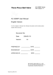
MAINTENANCE INTERVALS
Operation and Maintenance
Manual Excerpt
© 2010 Caterpillar
All Rights Reserved
®
®
SEBU7757-04
September 2009
Operation and
Maintenance
Manual
T6B, T9B and T15B Trenchers
KSK1-Up (T6B)
JAJ1-Up (T9B)
SLW1-Up (T15B)
SAFETY.CAT.COM
SEBU7757-04
45
Maintenance Section
Maintenance Interval Schedule
i03671827
Maintenance Interval Schedule
SMCS Code: 6700
When Required
Tool Bar Blade (Crumber) - Inspect/Adjust ........... 49
Daily
Chain - Inspect/Adjust ...........................................
Chain Teeth - Inspect/Replace ..............................
Frame Mounting Bracket - Inspect ........................
Idler Bearings - Lubricate ......................................
Tool Bar Blade (Crumber) - Inspect/Adjust ...........
46
46
48
49
49
Every 40 Service Hours or Weekly
Frame Slide Bar (Upper and Lower) - Lubricate ... 49
Hub - Lubricate ..................................................... 49
46
Maintenance Section
Chain - Inspect/Adjust
SEBU7757-04
i02356749
Chain - Inspect/Adjust
2. Use a wrench with “18 MM” box end in order to
loosen four clamp bolts (1) while you loosen nuts
(2). Repeat this procedure for each clamp bolt (1).
SMCS Code: 671C-025; 671C-040
Inspect
Illustration 47
g01032051
Some components are removed for clarity.
Illustration 45
g01177158
Inspect the chain for any wear or damage. Replace
the chain, if necessary.
Inspect the chain for the proper amount of chain
tension. The distance (A) between the inside of
the chain to the bottom of the boom should be
approximately 63.5 mm (2.50 inch) for the T9B
and T15B trenchers. The distance (A) between the
inside of the chain to the bottom of the boom should
be approximately 38 mm (1.50 inch) for the T6B
trencher. Adjust the chain, if necessary.
Note: A new chain stretches more readily than a
chain with more usage.
3. Apply grease to purge valve (5) in order to adjust
the chain tension so that the distance (A) between
the inside of the chain to the bottom of the boom
should be approximately 68.5 mm (2.50 inches)
for the T9B and T15B trenchers. The distance
(A) between the inside of the chain to the bottom
of the boom should be approximately 38 mm
(1.50 inches) for the T6B trencher.
4. Hold clamp bolts (1) with the “18 MM” box wrench
while you tighten the nuts (2).
5. Torque the four nuts (2) to 100 N·m (73.75 lb ft).
Continue to torque all four nuts in order to ensure
that all four nuts are evenly torqued to 100 N·m
(73.75 lb ft).
6. Use a “One Inch” box wrench to replace drain
plug (3).
Adjust
i02356790
Chain Teeth - Inspect/Replace
SMCS Code: 671C-040-TTH; 671C-510-TTH
Use the following procedure to access the lower half
of the chain tool. Inspect each tooth of the chain tool.
Replace each tooth of the chain, as required.
1. Enter the host machine. Fasten the seat belt.
2. Lower the armrest, if equipped.
Illustration 46
g01177161
1. Use a “One Inch” box wrench and remove one
drain plug (3).
3. Start the engine.
4. Disengage the parking brake.
5. Raise the trencher slightly off the ground.
SEBU7757-04
47
Maintenance Section
Chain Teeth - Inspect/Replace
6. Activate the auxiliary hydraulic control in order to
rotate the lower half of the chain to the top side of
the boom. Then, release the auxiliary hydraulic
control.
7. Lower the trencher to the ground.
8. Stop the engine and exit the host machine.
3. Replace the chain tooth. Install the hardware in
the proper order.
Replace Chain
Perform the following steps in order to replace the
chain from the trencher.
Inspect
Illustration 50
Illustration 48
g01177184
Inspect each tooth of the chain tool for wear. Replace
the teeth, if necessary. Ensure that the bolts for each
tooth are tightened.
Replace Teeth
g01032127
1. Use a wrench with “18 MM” box end and remove
four clamp bolts (1) and nuts (2).
a. Remove bolt (4).
b. Move the idler inward in order to increase slack
in the chain.
c. Remove the chain from the trencher.
2. Remove idler (9) from boom (8). Remove drain
plug (3) and remove purge valve (5).
3. Pull pushrod (7) and remove the adjuster cylinder
(6) from boom (8).
NOTICE
Care must be taken to ensure that fluids are contained
during performance of inspection, maintenance, testing, adjusting and repair of the product. Be prepared to
collect the fluid with suitable containers before opening any compartment or disassembling any component containing fluids.
Illustration 49
g01030154
Perform the following procedure on one chain link
and remove the chain tooth from the chain assembly.
1. Remove nuts (2).
2. Remove bolts (3) and remove tooth (1). Retain
brackets (4) and retain spacers (5), as required.
Note: Ensure that you replace the worn tooth (1)
with an identical tooth. Replace worn components or
damaged components with new hardware.
Refer to Special Publication, NENG2500, “Caterpillar
Dealer Service Tool Catalog” for tools and supplies
suitable to collect and contain fluids on Caterpillar
products.
Dispose of all fluids according to local regulations and
mandates.
4. Push pushrod (7) back into adjuster cylinder (6) in
order to drain the grease.
48
Maintenance Section
Frame Mounting Bracket - Inspect
SEBU7757-04
Note: After drainage, insert a new purge valve. Use
“Teflon” tape on the threads.
The chain group is used for digging sand or other
soft material.
5. Install adjuster cylinder (6) into boom (8). Make
sure that purge valve (5) aligns with the hole for
drain plug (3).
50/50 Carbide
a. Install new bolt (4).
6. Install idler (9) into boom (8). Replace clamp bolts
(1) and nuts (2) into the original position.
7. Install the chain on the trencher.
8. Apply grease to the purge valve in order to adjust
the chain tension so that the distance (A) between
the inside of the chain to the bottom of the boom
should be approximately 68.5 mm (2.50 inches)
for the T9B and T15B trenchers. The distance
(A) between the inside of the chain to the bottom
of the boom should be approximately 38 mm
(1.50 inches) for the T6B trencher.
9. Hold clamp bolts (1) with the “18 MM” box wrench
while you tighten the nuts (2).
10. Torque the four nuts (2) to 100 N·m (73.75 lb ft).
Continue to torque all four nuts in order to ensure
that all four nuts are evenly torqued to 100 N·m
(73.75 lb ft).
A 50/50 carbide chain group has carbide teeth and
standard cup teeth.
The chain group is used for ground conditions
that are medium digging up to hard digging. The
chain group is used for breaking the ground and for
removing the soil from the trench.
50/50 Rock-Frost
A 50/50 rock-frost chain group has rock teeth and
standard cup teeth.
The chain group is used for ground conditions
that are medium digging up to hard digging. The
chain group is used for breaking the ground and for
removing the soil from the trench. The chain group is
a great pick and shovel.
Rock-Frost
A rock-frost chain group has rock teeth on every link
pitch.
11. Use a “One Inch” box wrench to replace drain
plug (3).
The chain group is used for digging conditions that
are severe. The chain group is used for digging soil
such as caliche, rock, asphalt, frost, and hard clay.
Note: A new chain stretches more readily than a
chain with more usage. Adjust the chain, if necessary.
Consult your Caterpillar dealer for additional
information on replacement chain groups.
Chain Groups
Chain groups are available with different
configurations of teeth . Chain groups are available in
several widths. Refer to Service Manual, RENR4457,
“Trencher Tooth” for additional information on
replacing chain groups or replacing the entire chain.
i01988179
Frame Mounting Bracket Inspect
SMCS Code: 7050-040-MT
Single Standard
A single standard chain group has standard cup teeth
on alternate link assemblies.
The chain group is used for ground conditions that are
soft digging up to normal digging. The chain group is
used for digging sticky materials such as clay.
Double Standard
A double standard chain group has standard cup
teeth on every link assembly.
Illustration 51
Rear view
g01030185
SEBU7757-04
49
Maintenance Section
Frame Slide Bar (Upper and Lower) - Lubricate
Inspect upper angled plate (1) and ensure that the
plate is not bent or otherwise damaged. Inspect holes
(2) for wear and for damage. Inspect lower angled
plate (3) and ensure that the plate is not bent or
otherwise damaged. Consult your Caterpillar dealer if
any wear is suspected or any damage is suspected.
i02357003
Frame Slide Bar (Upper and
Lower) - Lubricate
Apply lubricant to the grease fitting for the hub
bearings. Perform this procedure from the machine
side.
i02356794
Idler Bearings - Lubricate
SMCS Code: 6248-086-BD
SMCS Code: 7050-086-BAR
Illustration 54
g01177188
1. Remove cover bolt (1) in order to access grease
fitting (2).
Illustration 52
g01177288
Apply lubricant to the grease fittings for the upper
slide bar and for the lower slide bar on the frame
mounting bracket.
2. Apply lubricant to grease fitting (2) for the idler.
3. Install cover bolt (1).
i02252338
i02356833
Hub - Lubricate
SMCS Code: 4184-086
Tool Bar Blade (Crumber) Inspect/Adjust
(If Equipped)
SMCS Code: 6304-BG; 6710-BG
Inspect the tool bar blade (crumber) (1) for any
damage. Replace the tool bar blade (crumber), if
necessary. Refer to Service Manual, RENR4457,
“Tool Bar Blade (Crumber) - Remove and Install” for
additional information.
Illustration 53
Front view
Grease fitting is on the opposite side of the hub.
g01177195
50
Maintenance Section
Tool Bar Blade (Crumber) - Inspect/Adjust
SEBU7757-04
Scraper with Nonadjustable Blade
Note: Chain groups are available with different
configurations of teeth . Chain groups are available in
several widths. Refer to Service Manual, RENR4457,
“Trencher Tooth” for additional information on
replacing chain groups or replacing the entire chain.
4. If the chain group is replaced, inspect the blade on
the scraper (6) for proper width. If a chain group
that has a different width has been mounted to
the trencher, the width of the blade will need to
be adjusted.
Note: The adjustable blade (6) is available in two
different widths in order to properly match the width
of the chain group.
Illustration 55
g01134001
1. Inspect the scraper (2) for any damage. Replace
the scraper, if necessary. Refer to Service Manual,
RENR4457, “Scraper - Remove and Install” for
additional information.
2. Inspect the scraper for proper movement. The
scraper must be able to move when a small force
is applied. If the scraper is unable to move, or if
the scraper is easily moved, inspect the torque on
the four bolts (3).
3. Torque the four bolts to 50 ± 10 N·m (37 ± 7 lb ft).
Scraper with Adjustable Blade
Table 9
Adjustable Scraper Blade Kit
Adjustable Width
Part Number
152.4 to 203.2 mm
(6 to 8 inch)
264-7597 Blade Kit
254.0 to 304.8 mm
(10 to 12 inch)
264-7598 Blade Kit
5. Loosen the two bolts (7) on the blade (6) in order
to adjust the width of the blade.
6. Adjust the two halves of the blade inward for
narrower chain groups. Adjust the two halves of
the blade outward for wider chain groups.
7. Adjust the two halves of the blade to the
appropriate width for the attached chain group and
for the ground conditions.
8. Tighten the two bolts (7) on the blade (6). Torque
the two bolts to 105 ± 20 N·m (77 ± 15 lb ft).
Illustration 56
g01134002
1. Inspect the scraper (4) for any damage. Replace
the scraper, if necessary. Refer to Service Manual,
RENR4457, “Scraper - Remove and Install” for
additional information.
2. Inspect the scraper for proper movement. The
scraper must be able to move when a small force
is applied. If the scraper is unable to move, or if
the scraper is easily moved, inspect the torque on
the four bolts (5).
3. Torque the four bolts to 50 ± 10 N·m (37 ± 7 lb ft).