1
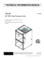
TECHNICAL INFORMATION MANUAL
Models listed
on page 2.
GMV95
40" 95% Gas Furnace Units
• All safety information must be followed as provided in
the Service Manual.
• Refer to the appropriate Parts Catalog for part number
information.
®
C
®
This manual is to be used by qualified HVAC technicians only. Goodman
does not assume any responsibility for property damage or personal injury
due to improper service procedures performed by an unqualified person.
US
RT6612012
September 2005
Copyright © 2005 Goodman Manufacturing Company, L.P.
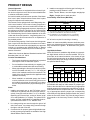
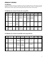
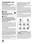
PRODUCT IDENTIFICATION
The model and manufacturing number are used for positive identification of component parts used in manufacturing.
Please use these numbers when requesting service or parts information.
G
M
V 95 045 5
B X
A
Product Type
Design Series
G: Goodman Brand
A: Initial Release
Additional Features
Supply Type
N: Natural Gas
C: Counterflow/Horizontal
M: Upflow/Horizontal
X: Low NOx
Cabinet Width
A: 14"
Furnace Type
B: 17 1/2"
V: Variable Speed - 2 Stage
C: 21"
D: 24 1/2"
Model Family
Airflow Capability
95: 95% AFUE
3: 1200
4: 1600
5: 2000
Nominal Input
045:
070:
090:
115:
45,000 Btuh
70,000 Btuh
90,000 Btuh
115,000 Btuh
MODELS
WARNING
GMV950453BXA
GMV950905DXA
GMV950704CXA
GMV951155DXA
IF REPAIRS ARE ATTEMPTED BY UNQUALIFIED PERSONS, DANGEROUS CONDITIONS (SUCH AS EXPOSURE TO ELECTRICAL SHOCK) MAY
RESULT. THIS MAY CAUSE SERIOUS INJURY OR DEATH.
THIS UNIT SHOULD NOT BE CONNECTED TO, OR USED IN CONJUNCWARNING TION WITH, ANY DEVICES THAT ARE NOT DESIGN CERTIFIED FOR USE
WITH THIS UNIT OR HAVE NOT BEEN TESTED AND APPROVED BY
GOODMAN. SERIOUS PROPERTY DAMAGE OR PERSONAL INJURY,
REDUCED UNIT PERFORMANCE AND/OR HAZARDOUS CONDITIONS MAY RESULT FROM THE USE
OF DEVICES THAT HAVE NOT BEEN APPROVED OR CERTIFIED BY GOODMAN.
GOODMAN WILL NOT BE RESPONSIBLE FOR ANY INJURY OR PROPERTY DAMAGE ARISING FROM IMPROPER SERVICE OR SERVICE
PROCEDURES. IF YOU PERFORM SERVICE ON YOUR OWN PRODUCT,
YOU ASSUME RESPONSIBILITY FOR ANY PERSONAL INJURY OR PROPERTY DAMAGE WHICH
MAY RESULT.
CAUTION
2
PRODUCT DESIGN
General Operation
The GMV95 furnaces are equipped with an electronic ignition device to light the burners and an induced draft blower
to exhaust combustion products.
An interlock switch prevents furnace operation if the blower
door is not in place. Keep the blower access doors in place
except for inspection and maintenance.
This furnace is also equipped with a self-diagnosing electronic control module. In the event a furnace component is
not operating properly, the control module LED will flash on
and off in a factory-programmed sequence, depending on
the problem encountered. This light can be viewed through
the observation window in the blower access door. Refer to
the Troubleshooting Chart for further explanation of the LED
codes and Abnormal Operation - Integrated Ignition Control section in the Service Instructions for an explanation of
the possible problem.
4. Installer must supply the following gas line fittings, depending on which entrance is used:
Left -- Two 90° Elbows, one close nipple, straight pipe
Right -- Straight pipe to reach gas valve.
Accessibility Clearances (Minimum)
GMV95 MINIMUM CLEARANCES TO COMBUSTIBLE MATERIALS
(INCHES)
POSITION* FRONT SIDES REAR
TOP
FLUE FLOOR
Upflow
3
0
0
1
0
C
Horizontal
3
6
0
6
0
C
*=
All positioning is determined as installed unit is viewed from the front.
C= If placed on combustible floor, floor MUST be wood only.
NC= For instalaltion on non-combustible floors only. A combustible
subbase must be used for installations on combustible flooring.
36" at front is required for servicing or cleaning.
The rated heating capacity of the furnace should be greater
than or equal to the total heat loss of the area to be heated.
The total heat loss should be calculated by an approved
method or in accordance with “ASHRAE Guide” or “Manual
J-Load Calculations” published by the Air Conditioning Contractors of America.
Note: In all cases accessibility clearance shall take precedence over clearances from the enclosure where accessibility clearances are greater. All dimensions are given in
inches.
*Obtain from: American National Standards Institute 1430
Broadway New York, NY 10018
When this furnace is installed at high altitude, the appropriate High Altitude orifice kit must be installed. This is required due to the natural reduction in the density of both
the gas fuel and combustion air as altitude increases. The
kit will provide the proper design certified input rate within
the specified altitude range.
Location Considerations
•
The furnace should be as centralized as is practical
with respect to the air distribution system.
•
Do not install the furnace directly on carpeting, tile,
or combustible material other than wood flooring.
•
When suspending the furnace from rafters or joists,
use 3/8" threaded rod and 2” x 2” x 1/8” angle as
shown in the Installation and Service Instructions. The
length of the rod will depend on the application and
clearance necessary.
•
When installed in a residential garage, the furnace
must be positioned so the burners and ignition source
are located not less than 18 inches (457 mm) above
the floor and protected from physical damage by vehicles.
Notes:
1. Installer must supply one or two PVC pipes: one for
combustion air (optional) and one for the flue outlet (required). Vent pipe must be either 2” or 3” in diameter,
depending upon furnace input, number of elbows, length
of run and installation (1 or 2 pipes). The optional Combustion Air Pipe is dependent on installation/code requirements and must be 2” or 3” diameter PVC.
High Altitude Derate
"STANDARD" and "HIGH ALTITUDE" KITS
0 - 7,000 Feet
(Standard Altitude)
7,001 - 9,000 Feet
9,001 - 11,000 Feet
Propane
ID Blwr
Pressure
Switch
GMV950453BXA
No
GMV950704CXA Change
LPM-03*
#55 Orifice
No
Change
HANG13
HALP11
#44
HAPS28
#56 Orifice
Orifice
HANG14
#45
Orifice
HALP11
#56
Orifice
HAPS28
GMV950905DXA
No
GMV951155DXA Change
LPM-03*
#55 Orifice
No
Change
HANG13
#44
Orifice
HANG14
#45
Orifice
HALP11
#56
Orifice
HAPS29
Furnace
Gas Orifices
Natural
Gas Orifices
Natural
Propane
HALP11
#56
Orifice
ID Blwr
Pressure
Switch
Natural
Propane
HAPS29
Gas Orifices
ID Blwr
Pressure
Switch
High altitude kits are purchased according to the installation altitude and usage of either natural or propane gas.
Refer to the chart above for a tabular listing of appropriate
altitude ranges and corresponding manufacturer’s high altitude Natural Gas and Propane Gas kits. For a tabular listing of appropriate altitude ranges and corresponding
manufacturer's High Altitude Pressure Switch kits, refer to
either the Pressure Switch Trip Points & Usage Chart in
this manual or the Accessory Charts in Service Instructions.
2. Line voltage wiring can enter through the right or left
side of the furnace. Low voltage wiring can enter through
the right or left side of furnace.
3. Conversion kits for propane gas and high altitude natural and propane gas operation are available. See High
Altitude Derate chart for details.
3
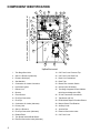
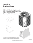
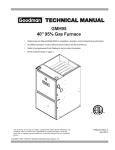
COMPONENT IDENTIFICATION
6
8
7
7
4
11
3
13
3
*
2
12
*
*
*
14
16
*
*
1
*
*
15
17 18
19
31 32
30
19
20
20
21
21
22
CFM
87
4321
87
4321
OFF
7
11
8
5
1
2
CUT FOR
DEHUM
ON
S4
10
4
S3
12
9
6
3
Intell-Ignition
TWO
TSTAT
SINGLE
BLOWER COMPARTMENT
9 10
*
BURNER COMPARTMENT
5
29
ON
C
S1
WR
23
3
2
1
OFF
US
24
26
28
27
25
Upflow/Horizontal
1
Two-Stage Gas Valve
19 Coil Front Cover Pressure Tap
2
Gas Line Entrance (Alternate)
20 Coil Front Cover Drain Port
3
Pressure Switch(es)
21 Drain Line Penetrations
4
Gas Manifold
22 Drain Trap
5
Combustion Air Intake Connection
23 Blower Door Interlock Switch
6
Hot Surface Igniter
24 Inductor (Not All Models)
7
Rollout Limit
25 Two-Stage Integrated Control Module
8
Burners
9
Flame Sensor
26 24 Volt Thermostat Connections
10 Flue Pipe Connection
27 Transformer (40 VA)
11 Flue Pipe
28 ECM Variable Speed Circulator Blower
12 Combustion Air Intake (Alternate)
29 Bottom Return Filter Retainer
13 Primary Limit
30 Auxiliary Limits
14 Gas Line Entrance
31 Junction Box
15 Flue Pipe Connection (Alternate)
32 Electrical Connection Inlets
16 Rubber Elbow
33 Coil Front Cover
17 Two-Speed Induced Draft Blower
18 Electrical Connection Inlets (Alternate)
4
(with fuse and diagnostic LED)
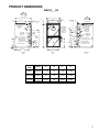
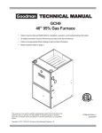
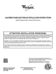
PRODUCT DIMENSIONS
GMV95___XA
AIR
DISCHARGE
A
28 3/4
B
(DISCHARGE AIR)
C
3/4
3/4
2 1/2
20 3/16
AIR INTAKE PIPE
2" PVC
ALTERNATE
GAS SUPPLY
HOLE
2 1/16
DRAIN
TRAP
CL
2 5/8
30 1/4
CONDENSATE
DRAIN TRAP
w/ 3/4" PVC
DISCHARGE
(RIGHT OR
LEFT SIDE)
40
LOW VOLTAGE
ELECTRICAL HOLE
HIGH VOLTAGE
ELECTRICAL HOLE
27 1/8
6 1/8
19 3/16
2 5/8
19 3/16
2
SIDE CUT-OUT
ALTERNATE
VENT/FLUE
LOCATION
4 1/8
30 1/4
1 3/4
ALTERNATE
AIR INTAKE LOCATION
STANDARD GAS
SUPPLY HOLE
2 11/16
23
14
VENT/FLUE PIPE
2" PVC
7 3/8
LEFT SIDE
DRAIN LINE
HOLES
AIR
DISCHARGE
3/4
HIGH VOLTAGE
ELECTRICAL HOLE
11 3/4
16 5/8
11 3/4
9 3/8
RIGHT SIDE
DRAIN LINE
DRAIN
HOLES
TRAP
CL
LOW VOLTAGE
ELECTRICAL HOLE
32 13/16
7 7/8
1 3/4
SIDE CUT-OUT
1 5/8
1 1/2
D
BOTTOM KNOCK-OUT
23 9/16
BOTTOM KNOCK-OUT
LEFT SIDE
VIEW
FRONT
VIEW
RIGHT SIDE
VIEW
`
CABINET
SIZE
UNITS
A
B
C
D
SMALL
0453BXA
17 1/2
15
12 3/8
12 5/8
21
19
16 3/8
14 5/8
24 1/2
23
20 3/8
18 5/8
MEDIUM 0704CXA
LARGE
0905DXA
1155DXA
All dimensions are in inches.
5
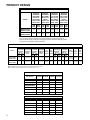
PRODUCT DESIGN
PRESSURE SWITCH TRIP POINTS AND USAGE CHART
NEGATIVE
PRESSURE
ID BLOWER
WITH FLUE
NOT FIRING
TYPICAL SEA
LEVEL DATA
NEGATIVE
PRESSURE
ID BLOWER
WITH FLUE
FIRING
TYPICAL SEA
LEVEL DATA
NEGATIVE
PRESSURE
COIL COVER
WITH FLUE
NOT FIRING
TYPICAL SEA
LEVEL DATA
NEGATIVE
PRESSURE
COIL COVER
WITH FLUE
FIRING
TYPICAL SEA
LEVEL DATA
LOW
FIRE
HIGH
FIRE
LOW
FIRE
HIGH
FIRE
LOW
FIRE
HIGH
FIRE
LOW
FIRE
HIGH
FIRE
GMV950453BXA
GMV950704CXA
-0.45
-0.90
-0.50
-0.95
-0.25
-0.25
-0.25
-0.25
GMV950905DXA
GMV951155DXA
-0.65
-1.20
-0.70
-1.25
-0.25
-0.25
-0.25
-0.25
MODEL
Note: The typical sea level negative pressure data represents the minimum pressures
expected. Shorter length of flue pipe or single pipe systems compared to dual pipe systems
should show higher (greater negative) pressures.
PRESSURE SWITCH TRIP POINTS AND USAGE CHART
0 to 7,000 ft.
MODEL
TRIP POINT
COIL COVER
PRESSURE
SWITCH
LOW
FIRE
HIGH
FIRE
GMV950453BXA
GMV950704CXA
-0.10
-0.10
GMV950905DXA
GMV951155DXA
-0.10
-0.10
COIL COVER
PRESSURE
SWITCH
PART #
TRIP POINT
ID BLOWER
PRESSURE
SWITCH
7,001 ft. to 11,000 ft.
ID BLOWER
PRESSURE
SWITCH
PART #
PS1
LABEL
COLOR
PS2
LABEL
COLOR
TRIP POINT
COIL COVER
PRESSURE
SWITCH
TRIP POINT
ID BLOWER
PRESSURE
SWITCH
LOW
FIRE
HIGH
FIRE
LOW
FIRE
HIGH
FIRE
HIGH
ALTITUDE
KIT
PS1
LABEL
COLOR
GREEN YELLOW
LOW
FIRE
HIGH
FIRE
20197301
-0.30
-0.75
11177113
PURPLE
PINK
-0.10
-0.10
-0.22
-0.55
HAPS28
11177115
20197301
-0.50
-1.10
11177114
WHITE
GRAY
-0.10
-0.10
-0.38
-0.82
HAPS29
ORANGE LT BLUE
11177116
Note: All installations above 7,000 ft. require a pressure switch change. For installations in Canada the GMV95 furnaces are certified only to 4500 ft.
Note: Replacement pressure switch number is listed below high altitude kit number.
Note: All negative pressure readings are in inches of water column (" w.c.).
T.O.D. PRIMARY LIMIT
Part Number
20162903 20162905 20162907 20162908
Open Setting (°F)
160
145
155
170
Color Code(s)
Blue
Yellow
Orange
Green
1
GMV950453BXA
1
GMV950704CXA
1
GMV950905DXA
GMV951155DXA
1
ROLLOUT LIMIT SWITCHES
Part Number
10123517
10123518
10123533
10123537
Open Setting (°F)
210
170
200
190
Color Code(s)
White
Blue
Yellow
Gray
GMV950453BXA
GMV950704CXA
1
2
2
GMV950905DXA
GMV951155DXA
6
PS2
LABEL
COLOR
2
PRODUCT DESIGN
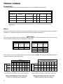
Coil Matches:
A large array of Amana® brand coils are available for use with the new GMV95 furnaces, in either upflow or horizontal
applications. These coils are available in both cased and uncased models, with or without a TXV expansion device.
These new 95%+ furnaces match up with the existing Amana® brand coils as shown in the chart below.
Coil Matches (for Amana® brand units using R22):
CABINET
WIDTH
CAUF
UNCASED
"A" COILS
CAUX
UNCASED
TXV "A" COILS
CACF
CASED
"A" COILS
CAPF
CASED
"A" COILS
CAUX018B2*
CAUX025B2*
CAUX036B2*
CAUX037B2*
CAUX042B2*
CACF030B2*
CACF036B2*
CACF042B2*
CACF048B2*
CAPF018B2*
CAPF025B2*
CAPF030B2*
CAPF039B2*
CAPF036B2*
CAPF037B2*
CAPF042B2*
CAPX018B2*
CAPX025B2*
CAPX030B2*
CAPX036B2*
CAPX037B2*
CAPX042B2*
CHPF036B2*
CHPF042B2*
CHPF048B2*
CHPX036B2*
CHPX042B2*
1 1/2 - 3
CAUF018B2*
CAUF025B2*
CAUF030B2*
CAUF036B2*
CAUF037B2*
CAUF042B2*
CAUF048B2*
CAUX049C2*
CAPX049C2*
CHPF048D2*
CHPF060D2*
CHPX048D2*
CHPX060D2*
1 1/2 - 4
CACF042C2*
CACF048C2*
CACF060C2*
CACF061C2*
CAPF036C2*
CAPF042C2*
GMV950704CXA
CAUF042C2*
CAUF048C2*
CAUF049C2*
CAUF060C2*
CAUF061C2*
GMV950905DXA
GMV951155DXA
2-5
CAUF049D2*
CAUF060D2*
CAUF061D2*
CAUX049D2*
CAUX060D2*
CAUX061D2*
CACF060D2*
CACF061D2*
CAPF049D2*
CAPF060D2*
CAPX049D2*
CAPX060D2*
CAPX061D2*
CHPF048D2*
CHPF060D2*
CHPX048D2*
CHPX060D2*
FURNACE
MODELS
AIRFLOW
(tons)
1 1/2 - 3
17 1/2
21
24 1/2
GMV950453BXA
CAPX
CHPF
CHPX
CASED
HORIZ. CASED HORIZ. CASED
TXV "A" COILS
"A" COIL
TXV "A" COIL
Coil Matches (for Amana® brand RSD units using R-410A):
CABINET
WIDTH
17 1/2
21
24 1/2
AIRFLOW
(tons)
CAUF
UNCASED
"A" COILS
CAUX
UNCASED
TXV "A" COILS
CAPF
CASED
"A" COILS
1 1/2 - 3
CAUF030B4*
CAUF036B4*
CAUX030B4*
CAUX036B4*
CAUX042B4*
CAPF030B4*
CAPF036B4*
CAPX030B4*
CAPX036B4*
1 1/2 - 4
CAUF042C4*
CAUF048C4*
CAUF057D4*
CAUX042C4*
CAUX048C4*
CAUX057D4*
CAUX060D4*
CAPF042C4*
GMV950704CXA
CAPX042C4*
CAPX048C4*
GMV950905DXA
GMV951155DXA
2-5
CAUX057D4*
CAUX060D4*
CAPF057D4*
CAPF060D4*
CAPX057D4*
CAPX060D4*
FURNACE
MODELS
GMV950453BXA
CAPX
CHPF
CHPX
CASED
HORIZ. CASED HORIZ. CASED
TXV "A" COILS
"A" COIL
TXV "A" COIL
CHPF036B4*
CHPX036B4*
CHPF048D4*
CHPF060D4*
CHPX048D4*
CHPX060D4*
7
PRODUCT DESIGN
Thermostats:
The following Amana® brand thermostats are suggested for use with GMV95 Furnace Models:
THERMOSTATS
Thermostat
Man/Auto
Programmable
Cool Heat Batt. Powered Batt. Bkup
1213406*
Man. Or Auto
Yes
2
3
No
No
1213407
Man. Changeover
Yes
2
2
Yes
Yes
1213411
Man. Changeover
No
2
2
Yes
No
*1213406 is the recommended model for the GMV95 furnaces when used with a heat pump in a fossil fuel
application. It is NOT for use with the GMV95 as a sole heating source. 1213406 therm ostats are 24V powered with
battery backup.
Filters:
Filters are required with this furnace and must be provided by the installer. The filters used must comply with UL900 or
CAN/ULCS111 standards. Installing this furnace without filters will void the unit warranty
Upflow Filters
This furnace has provisions for the installation of return air filters at the side and/or bottom return. The furnace will
accommodate the following filter sizes depending on cabinet size:
Cabinet
Width
(in.)
All
SIDE RETURN
Approx.
Nominal
Flow
Area
Filter Size
(in.)
(in2)
16 x 25 x 1
400
BOTTOM RETURN
Approx.
Cabinet
Nominal
Flow
Area
Width
Filter Size
(in.)
(in.)
(in2)
17-1/2
14 x 25 x 1
350
21
16 x 25 x 1
400
24-1/2
20 x 25 x 1
500
Refer to Minimum Filter Area tables to determine filter area requirement. NOTE: Filters can also be installed elsewhere
in the duct system such as a central return.
UPFLOW
COOLING AIRFLOW REQUIREMENT (CFM)
600
800
1000
1200
1400
1600
2000
0453__XA
376*
384
480
576
---
---
---
0704__XA
---
---
564*
564*
672
768
0905__XA
---
---
---
752*
752*
768
960
1155__XA
---
---
---
940*
940*
940*
960
Input__Airflow
Input__Airflow
UPFLOW
COOLING AIRFLOW REQUIREMENT (CFM)
600
800
1000
1200
1400
1600
2000
0453__XA
376*
384
480
576
---
---
---
0704__XA
---
---
627*
627*
672
768
---
0905__XA
---
---
---
836*
836*
836*
960
1155__XA
---
---
---
940*
940*
940*
960
*Minimum filter area dictated by heating airflow requirement.
*Minimum filter area dictated by heating airflow requirement.
Disposable Minimum Filter Area (in2)
Permanent Minimum Filter Area (in2)
[Based on a 300 ft/min filter face velocity]
[Based on 600 ft/min filter face velocity]
8
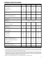
FURNACE SPECIFICATIONS
MODEL
GMV950453BXA
GMV950704CXA
GMV950905DXA
GMV951155DXA
Btuh Input (US) High Fire
46,000
69,000
92,000
115,000
Output (US) High Fire
44,300
66,900
88,800
111,100
Btuh Input (US) Low Fire
32,000
48,000
64,000
80,000
Output (US) Low Fire
30,800
46,400
61,700
77,400
96%
95.5%
95.7%
95.8%
Rated External Static (" w.c.)
.10 - .50
.10 - .50
.10 - .50
.10 - .50
Temperature Rise (°F)
30 - 60
30 - 60
30 - 60
35 - 65
High Stage Pressure Switch Trip Point (" w.c.)
-0.75
-0.75
-1.10
-1.10
Low Stage Pressure Switch Trip Point (" w.c.)
-0.30
-0.30
-0.50
-0.50
Front Cover Pressure Switch Trip Point (" w.c)
-0.10
-0.10
-0.10
-0.10
Blower Wheel (D" x W")
10 x 7
10 x 10
11 x 10
11 x 10
1/2
3/4
1
1
A.F.U.E.
Blower Horsepower
Blower Speeds
Refer to airflow charts on pages 10-13.
Max CFM @ 0.5 E.S.P.
Power Supply
115-60-1
115-60-1
115-60-1
115-60-1
10.4
12.8
14.6
14.6
15
15
15
15
Transformer (VA)
40
40
40
40
Heat Anticipator (Amps)
0.7
0.7
0.7
0.7
Primary Limit Setting (°F)
145
155
145
160
Auxiliary Limit Setting (°F)
150
190
180
200
Rollout Limit Setting (°F)
170
200
190
200
Minimum Circuit Ampacity (MCA)
Maximum Overcurrent Device
Fan Delay On Heating
30 secs.
30 secs.
30 secs.
30 secs.
150 secs.
150 secs.
150 secs.
150 secs.
5 secs.
5 secs.
5 secs.
5 secs.
Off Cooling
45 secs.
45 secs.
45 secs.
45 secs.
Fan Delay On - Fan Only
5 secs.
5 secs.
5 secs.
5 secs.
7 / 11
7 / 11
7 / 11
7 / 11
Manifold Pressure (Natural/Propane) High Stage (" w.c.)
3.5 / 10
3.5 / 10
3.5 /10
3.5 /10
Manifold Pressure (Natural/Propane) Low Stage ("w.c.)
1.9 / 6.0
1.9 / 6.0
1.9 / 6.0
1.9 / 6.0
Orifice Size (Natural/Propane)
#43 / #55
#43 / #55
#43 / #55
#43 / #55
Number of Burners
2
3
4
5
Vent Connector Diameter (inches)
2
2
3
3
Combustion Air Connector Diameter (inches)
2
2
3
3
133
157
172
184
Off Heating *
Fan Delay On Cooling
Gas Supply Pressure (Natural/Propane) (" w.c.)
Shipping Weight (lbs.)
* Off Heating - This fan delay timing is adjustable (90, 120, 150 or 180 seconds), 150 seconds as shipped.
1. These furnaces are manufactured for natural gas operation. Optional Kits are available for conversion to propane gas operation.
2. For elevations above 2000 ft. the rating should be reduced by 4% for each 1000 ft. above sea level. The furnace must not be
derated, orifice changes should only be made if necessary for altitude.
3. The total heat loss from the structure as expressed in TOTAL BTU/HR must be calculated by the manufactures method in
accordance with the "A.S.H.R.A.E. GUIDE" or "MANUAL J-LOAD CALCULATIONS" published by the AIR CONDITIONING
CONTRACTORS OF AMERICA. The total heat loss calculated should be equal to or less than the heating capacity. Output
based on D.O.E. test procedures, steady state efficiency times output.
4. Minimum Circuit Ampacity calculated as: (1.25 x Circulator Blower Amps) + I.D. Blower Amps.
9
FURNACEPERFORMANCE
SPECIFICATIONS
BLOWER
SPECIFICATIONS
GMV95 Heating Speed Charts
GMV950453BXA (Rise Range: 30 - 60°F)
Heating
Speed
Tap
A
B
C
D
GMV950704CXA (Rise Range: 30 - 60°F)
Adjust
Tap
Low Stage
CFM
at .1" - .5" w.c.
ESP
High Stage
CFM
at .1" - .5" w.c.
ESP
Rise
(°F)
Minus(-)
Normal
Plus (+)
Minus(-)
Normal
Plus (+)
Minus(-)
Normal
Plus (+)
Minus(-)
Normal
Plus (+)
495
550
605
540
600
660
585
650
715
630
700
770
713
792
871
778
864
950
842
936
1030
907
1008
1109
57
51
46
52
47
43
48
43
39
45
40
36
Heating
Speed
Tap
A
B
C
D
GMV950905DXA (Rise Range: 30 - 60°F)
Heating
Speed
Tap
A
B
C
D
Adjust
Tap
Low Stage
CFM
at .1" - .5" w.c.
ESP
High Stage
CFM
at .1" - .5" w.c.
ESP
Rise
(°F)
Minus(-)
Normal
Plus (+)
Minus(-)
Normal
Plus (+)
Minus(-)
Normal
Plus (+)
Minus(-)
Normal
Plus (+)
756
840
924
828
920
1012
900
1000
1100
972
1080
1188
1089
1210
1331
1192
1325
1457
1296
1440
1584
1400
1555
1711
56
50
46
51
46
42
47
42
38
43
39
35
GMV951155DXA (Rise Range: 30 - 60°F)
Adjust
Tap
Low Stage
CFM
at .1" - .5" w.c.
ESP
High Stage
CFM
at .1" - .5" w.c.
ESP
Rise
(°F)
Minus(-)
Normal
Plus (+)
Minus(-)
Normal
Plus (+)
Minus(-)
Normal
Plus (+)
Minus(-)
Normal
Plus (+)
1013
1125
1238
1076
1195
1315
1139
1265
1392
1202
1335
1469
1458
1620
1782
1549
1721
1893
1639
1822
2004
1730
1922
2115
56
50
45
52
47
43
49
44
40
47
42
38
Heating
Speed
Tap
A
B
C
D
Adjust
Tap
Low Stage
CFM
at .1" - .5" w.c.
ESP
High Stage
CFM
at .1" - .5" w.c.
ESP
Rise
(°F)
Minus(-)
Normal
Plus (+)
Minus(-)
Normal
Plus (+)
Minus(-)
Normal
Plus (+)
Minus(-)
Normal
Plus (+)
1107
1230
1353
1139
1265
1392
1170
1300
1430
1202
1335
1469
1594
1771
1948
1639
1822
2004
1685
1872
2059
1730
1922
2115
63
57
52
62
56
50
60
54
49
58
53
48
1. These furnaces are manufactured for natural gas operation. Optional Kits are available for conversion to propane gas operation.
2. For elevations above 2000 ft. the rating should be reduced by 4% for each 1000 ft. above sea level. The furnace must not be
derated, orifice changes should only be made if necessary for altitude.
3. The total heat loss from the structure as expressed in TOTAL BTU/HR must be calculated by the manufactures method in
accordance with the "A.S.H.R.A.E. GUIDE" or "MANUAL J-LOAD CALCULATIONS" published by the AIR CONDITIONING
CONTRACTORS OF AMERICA. The total heat loss calculated should be equal to or less than the heating capacity. Output
based on D.O.E. test procedures, steady state efficiency times output.
4. Minimum Circuit Ampacity calculated as: (1.25 x Circulator Blower Amps) + I.D. Blower Amps.
10
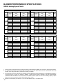
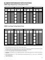
BLOWER PERFORMANCE SPECIFICATIONS
GMV95 High (Single) Stage Cooling Speed Charts
GMV950453BXA
Cooling
Speed
Tap
A
B
C
D
Adjust
Tap
CFM at
.1" - .8"
w.c. ESP
Minus(-)
Normal
Plus (+)
Minus(-)
Normal
Plus (+)
Minus(-)
Normal
Plus (+)
Minus(-)
Normal
Plus (+)
540
600
660
720
800
880
900
1000
1100
1080
1200
1320
GMV950704CXA
Cooling
Speed
Tap
A
B
C
D
Adjust
Tap
CFM at
.1" - .8"
w.c. ESP
Minus(-)
Normal
Plus (+)
Minus(-)
Normal
Plus (+)
Minus(-)
Normal
Plus (+)
Minus(-)
Normal
Plus (+)
540
600
660
720
800
880
990
1100
1210
1286
1429
1572
GMV950905DXA
Cooling
Speed
Tap
A
B
C
D
Adjust
Tap
CFM at
.1" - .8"
w.c. ESP
Minus(-)
Normal
Plus (+)
Minus(-)
Normal
Plus (+)
Minus(-)
Normal
Plus (+)
Minus(-)
Normal
Plus (+)
720
800
880
990
1100
1210
1260
1400
1540
1620
1800
1980
GMV951155DXA
Cooling
Speed
Tap
A
B
C
D
Adjust
Tap
CFM at
.1" - .8"
w.c. ESP
Minus(-)
Normal
Plus (+)
Minus(-)
Normal
Plus (+)
Minus(-)
Normal
Plus (+)
Minus(-)
Normal
Plus (+)
720
800
880
990
1100
1210
1260
1400
1540
1620
1800
1980
GMV95 Low Stage Cooling Speed Charts
GMV950453BXA
Cooling
Speed
Tap
A
B
C
D
Adjust
Tap
CFM at
.1" - .8"
w.c. ESP
Minus(-)
Normal
Plus (+)
Minus(-)
Normal
Plus (+)
Minus(-)
Normal
Plus (+)
Minus(-)
Normal
Plus (+)
380*
390
429
468
520
572
585
650
715
702
780
858
GMV950704CXA
Cooling
Speed
Tap
A
B
C
D
Adjust
Tap
CFM at
.1" - .8"
w.c. ESP
Minus(-)
Normal
Plus (+)
Minus(-)
Normal
Plus (+)
Minus(-)
Normal
Plus (+)
Minus(-)
Normal
Plus (+)
378*
390
429
468
520
572
644
715
787
836
929
1022
GMV950905DXA
Cooling
Speed
Tap
A
B
C
D
Adjust
Tap
CFM at
.1" - .8"
w.c. ESP
Minus(-)
Normal
Plus (+)
Minus(-)
Normal
Plus (+)
Minus(-)
Normal
Plus (+)
Minus(-)
Normal
Plus (+)
513*
520
572
644
715
787
819
910
1001
1053
1170
1287
GMV951155DXA
Cooling
Speed
Tap
A
B
C
D
Adjust
Tap
CFM at
.1" - .8"
w.c. ESP
Minus(-)
Normal
Plus (+)
Minus(-)
Normal
Plus (+)
Minus(-)
Normal
Plus (+)
Minus(-)
Normal
Plus (+)
514*
520
572
644
715
787
819
910
1001
1053
1170
1287
1. Units are shipped without filter(s). CFM in chart is without filter(s).
2. All furnaces shipped with heating speed set at "B" and cooling speed set at "D". Installer should adjust blower speed
as needed. The first task is to determine the proper aiflow for the cooling system.
3. For most cooling applications, about 400 CFM per ton is desirable.
4. The chart is for information only. For satisfactory operation, external static pressure not to exceed value shown on
rating plate.
5. Do not operate above 0.5" w.c. ESP in heating mode. Operating between 0.5" w.c. and 0.8" w.c. is tabulated for
cooling purposes only.
6. * Motor CFM minimum.
11
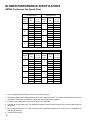
BLOWER PERFORMANCE SPECIFICATIONS
GMV95 Continuous Fan Speed Chart
GMV950453BXA
Cooling
Speed
Tap
A
B
C
D
Adjust
Tap
CFM at
.1" - .8"
w.c. ESP
Minus(-)
Normal
Plus (+)
Minus(-)
Normal
Plus (+)
Minus(-)
Normal
Plus (+)
Minus(-)
Normal
Plus (+)
380*
380*
380*
403
448
493
504
560
616
505
672
739
GMV950704CXA
Cooling
Speed
Tap
A
B
C
D
GMV950905DXA
Cooling
Speed
Tap
A
B
C
D
Adjust
Tap
CFM at
.1" - .8"
w.c. ESP
Minus(-)
Normal
Plus (+)
Minus(-)
Normal
Plus (+)
Minus(-)
Normal
Plus (+)
Minus(-)
Normal
Plus (+)
513*
513*
513*
554
616
678
706
784
862
907
1008
1109
Adjust
Tap
CFM at
.1" - .8"
w.c. ESP
Minus(-)
Normal
Plus (+)
Minus(-)
Normal
Plus (+)
Minus(-)
Normal
Plus (+)
Minus(-)
Normal
Plus (+)
380*
380*
380*
403
448
493
554
616
678
720
800
880
GMV951155DXA
Cooling
Speed
Tap
A
B
C
D
Adjust
Tap
CFM at
.1" - .8"
w.c. ESP
Minus(-)
Normal
Plus (+)
Minus(-)
Normal
Plus (+)
Minus(-)
Normal
Plus (+)
Minus(-)
Normal
Plus (+)
514*
514*
514*
554
616
678
706
784
862
907
1008
1109
1. Units are shipped without filter(s). CFM in chart is without filter(s).
2. All furnaces shipped with heating speed set at "B" and cooling speed set at "D". Installer should adjust blower speed
as needed. The first task is to determine the proper aiflow for the cooling system.
3. For most cooling applications, about 400 CFM per ton is desirable.
4. The chart is for information only. For satisfactory operation, external static pressure not to exceed value shown on
rating plate.
5. Do not operate above 0.5" w.c. ESP in heating mode. Operating between 0.5" w.c. and 0.8" w.c. is tabulated for
cooling purposes only.
6. * Motor CFM minimum.
12
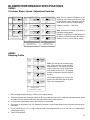
BLOWER PERFORMANCE SPECIFICATIONS
GMV95
Circulator Blower Speed Adjustment Switches
8 7 6 5
Normal
4 3 2 1
*
O
F
F
8 7 6 5 4
O
F
F
3 2 1
+ (Plus)
Adjust
O O
F N
F
8 7 6 5 4 3 2 1
- (Minus)
Adjust
O O
N F
F
Adjust Taps
(* indicates factory setting)
8 7 6 5
4 3 2 1
Cooling
Speed
Tap A
O
F
F
4 3 2
8 7 6 5
Cooling
Speed
Tap B
O O
F N
F
4 3 2 1
8 7 6 5
Cooling
Speed
Tap C
Cooling
Speed
Tap D
*
O
F
F
1
O O
N F
F
4 3 2 1
8 7 6 5
O O
N N
Heating
Speed
Tap A
Heating
Speed
Tap B
Heating
Speed
Tap C
Heating
Speed
Tap D
8 7 6 5
4 3 2 1
O
F
F
8
4 3 2 1
O
F
F
7 6 5
*
Note: There is a green LED adjacent to the
integrated control module fuse which is used
to verify airflow volume. The green CFM LED
blinks once for each 100 CFM of airflow.
Example: 10 blinks = 1,000 CFM
O O
F N
F
8 7 6 5
4 3 2 1
O O
N F
F
8 7 6 5
4 3 2 1
O O
N N
Cooling Speed Taps
Heating Speed Taps
(* indicates factory setting)
(* indicates factory setting)
Note: Continuous fan speed will be 56% of
high stage cooling speed.
Example: 1,000 CFM of cooling speed will
be reduced to 560 CFM when fan selector
switch is set to on, and no call for cooling.
GMV95
Ramping Profile
8 7 6 5 4 3 2 1
*
Ramping
Profile
Tap A
Ramping
Profile
Tap B
Ramping
Profile
Tap C
Ramping
Profile
Tap D
O
F
F
8 7 6
O
F
F
5 4 3 2 1
O O
F N
F
8 7 6 5 4 3 2 1
O O
N F
F
8 7 6 5 4 3 2 1
Note: The multi-speed circulator blower
also offers several custom ON/OFF
ramping profiles. These profiles may be
used to enhance cooling performance
and increase comfort level. The ramping
profiles are selected using DIP switches
5 and 6.
Verify profile selection by counting the
green CFM LED blinks and timing each
step of the ramping profile.
O O
N N
Ramping Profiles
(* indicates factory setting)
1. Units are shipped without filter(s). CFM in chart is without filter(s).
2. All furnaces shipped with heating speed set at "B" and cooling speed set at "D". Installer should adjust blower speed
as needed. The first task is to determine the proper aiflow for the cooling system.
3. For most cooling applications, about 400 CFM per ton is desirable.
4. The chart is for information only. For satisfactory operation, external static pressure not to exceed value shown on
rating plate.
5. Do not operate above 0.5" w.c. ESP in heating mode. Operating between 0.5" w.c. and 0.8" w.c. is tabulated for
cooling purposes only.
6. * Motor CFM minimum.
13
14
10
20
30
40
50
60
70
30
80
90
100
40
50
60
700
600 CFM
90
100
2000
2200
2400 CFM
1800
1600
1400
OUTPUT BTU/HR x 1000
80
1200
1100
1000
900
70
800
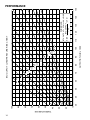
FORMULAS
110
120
130
140
BTU OUTPUT = CFM x 1.08 x RISE
BTU OUTPUT
RISE =
÷ CFM
1.08
BTU OUTPUT vs TEMPERATURE RISE CHART
150
PERFORMANCE
TEMPERATURE RISE
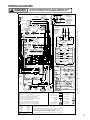
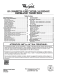
WIRING DIAGRAMS
! WARNING
TO AVOID POSSIBLE ELECTRICAL SHOCK, PERSONAL INJURY,
OR DEATH, DISCONNECT THE POWER BEFORE SERVICING.
ID BLOWER
TWO-STAGE PRESSURE
SWITCH ASSEMBLY
HI
C
2
PM
1
RD
WH
TWO STAGE
GAS VALVE
VT
3
N
BR
WH-5
C
GY
NO
RD
BU
AUTO RESET PRIMARY
LIMIT CONTROL
1
BK
SWITCH
BLOWER COMPARTMENT
GND
YL
PK
BK
11
BU
12
GY
WH
RD
7
8
9
4
5
6
1
2
3
GY
EAC-H
IND HI
IND LO
HUM-H
FP (3)
BU
FLAME SENSOR
GN
XFMR-H
2
HEAT OFF DELAY
DIP SWITCHES
PK
1
3
4
WH
DIAGNOSTIC
LED
GY
3
24
VAC
115
VAC
5
BK
XFMR
HUM
LINE
PARK
COOL
EAC
HI
HEAT
LO
HEAT
40VA
TRANSFORMER
BK
W1
HLO (11)
MANUAL RESET ROLLOUT
LIMIT CONTROL(S)
YLO
HL1 (6)
W2
Y
TO
MICRO
C
6
WH
5
BK
BK
BK
WH
GND
PK
INDUCTOR COIL
70kBTU,90kBTU,
115kBTU MODELS
ONLY
0
STEADY ON = NORMAL OPERATION
1
1 FLASH = SYSTEM LOCKOUT (RETRIES/RECYCLES EXCEEDED)
2
2 FLASHES = LOW FIRE PRESSURE SWITCH STUCK CLOSED
3
3 FLASHES = LOW FIRE PRESSURE SWITCH STUCK OPEN
C
HIGH FIRE
PRESSURE SWITCH
MVC (8)
GND (10)
BLOWER
COMPARTMENT
DOOR SWITCH
(OPEN WHEN
DOOR OPEN)
GND
TR (9)
INTEGRATED CONTROL MODULE
LOW VOLTAGE (24V)
EQUIPMENT GND
LOW VOLTAGE FIELD
FIELD SPLICE
HI VOLTAGE FIELD
5 FLASHES = FLAME SENSED WITH GAS VALVE DE-ENERGIZED
JUNCTION
7
7 FLASHES = LOW FLAME SENSE SIGNAL
TERMINAL
8
8 FLASHES = CHECK IGNITER OR IMPROPER GROUNDING
9
9 FLASHES = HIGH FIRE PRESSURE SWITCH STUCK OPEN
C
CONTINUOUS FLASHES = 115 VOLT AC POWER REVERSED
INTERNAL TO
INTEGRATED CONTROL
SWITCH (TEMP.)
IGNITER
SWITCH (PRESS.)
PLUG CONNECTION
PK PINK
NOTES:
BR BROWN
1. SET HEAT ANTICIPATOR ON ROOM THERMOSTAT AT 0.7 AMPS.
OR ORANGE
WH WHITE
2. MANUFACTURER'S SPECIFIED REPLACEMENT PARTS MUST BE USED WHEN SERVICING.
VT VIOLET
BU BLUE
GY GRAY
RD RED
22314701 REV.00
C
GAS
VALVE
FIELD GND
HI VOLTAGE (115V)
4 FLASHES = THERMAL PROTECTIVE DEVICE OPEN
GN GREEN
HI
PS2 (2)
4
BK BLACK
PM
NO
MVH (1)
6
COLOR CODES:
YL YELLOW
LOW FIRE
PRESSURE
SWITCH
C
24V HUMIDIFIER
WH
GN
C
NO
NO
MVL(7)
WH
BK
24V HUM.
PS1 (12)
FRONT COVER
PRESSURE SWITCH
WH
CIRCULATOR
BLOWER
4
3
2
1
MANUALRESET AUXILIARY LIMIT
CONTROLS
G
NEUTRAL
HOT
AUTORESET
PRIMARYLIMIT
CONTROL
24 VAC
FUSE 3 A
9 CIRCUIT CONNECTOR
RD
WH
OR
40 VA
TRANSFORMER
TH (5)
R
1
4
24V THERMOSTAT CONNECTIONS
2
5 CIRCUIT
CONNNECTOR
RD
BK
5
XFMR-N
115 VAC
VT
T-STAT SELECTOR
16 WIRE
ECM MTR
HARNESS
IGN-N
HOT SURFACE
IGNITER
OR
TWO-STAGE
INTEGRATED
CONTROL
MODULE
HUM-N
HUMIDIFIER
IGN-H
VT
YL
IND-N
ID
BLWR
OR
BR
EAC-N
ELECTRONIC
AIR CLEANER
INTEGRATED CONTROL MODULE
BR
RD
TWIN/
DEHUM
W2
R
W1
G
B/C
Y
YLO
O
WH
INTEGRATED CONTROL MODULE
VT
YL
PK
24 V THERMOSTAT CONNECTIONS
FUSE
LINE-N
LINE-H
GY
24V HUM.
10
INDOOR
AIR
CIRCULATOR
BLWR
VT
MANUAL RESET
AUXILIARY
LIMIT CONTROL
24 V
3A
JUNCTION BOX
115kBTU MODELS
INDUCTOR COIL
70kBTU,90kBTU,
ONLY
GND
BURNER COMPARTMENT
DISCONNECT
DOOR
INDUCED
DRAFT
BLOWER
GN
RD
VT
VT
2
BU
OR
N
GND
DISCONNECT POWER
MUST BE PROPERLY
BEFORE SERVICING.
WIRING TO UNIT
POLARIZED AND
GROUNDED.
CHASSIS GROUND
LOW FIRE
PRESS.
SWITCH
24V HUM.
PK
WH
L
WARNING:
MANUAL RESET ROLLOUT
LIMIT CONTROLS
(SINGLE CONTROL ON 45 kBTU)
WARNING:DISCONNECT
PROPERLY POLARIZED
SERVICING. WIRING
TO UNIT MUST BE
AND GROUNDED.
POWER BEFORE
TO 115VAC/ 1Ø /60 HZ POWER SUPPLY WITH
OVERCURRENT PROTECTION DEVICE
C
FRONT COVER
PRESSURE SWITCH
3
DISCONNECT
FLAME
SENSOR
GY
NO
BU
L
BK
-1
Wiring is subject to change, always refer to the wiring diagram on the unit for the most up-to-date wiring.
1
C
NO
OR
2 CIRCUIT
CONNECTOR
YL
2
HIGH FIRE
PRESS. SWITCH
115 VAC/ 1Ø /60 HZ
POWER SUPPLY WITH
PROTECTION DEVICE
OVERCURRENT
JUNCTION BOX
HOT
SURFACE
IGNITER
TO
GND
OVERCURRENT
PROT. DEVICE
3. IF ANY OF THE ORIGINAL WIRE AS SUPPLIED WITH THE FURNACE MUST BE
REPLACED, IT MUST BE REPLACED WITH WIRING MATERIAL HAVING A TEMPERATURE
RATING OF AT LEAST 105°C. USE COPPER CONDUCTORS ONLY.
4. UNIT MUST BE PERMANENTLY GROUNDED AND CONFORM TO N.E.C. AND LOCAL CODES.
15
C
US
ON
S1
TSTAT
S4
CFM
3
2
1
OFF
87 4321
87 4321
EAC
TWO
HUM
LINE
XFMR
PARK
COOL
HI
HEAT
LO
HEAT
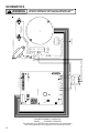
BLOWER ASSEMBLY SCHEMATIC
GMV95_____XA MODEL FURNACES
This schematic is for reference only. Not all wiring is as shown above,
refer to the appropriate wiring diagram for the unit being serviced.
LOAD
LINE
WH
XFMR
TRANSFORMER
BK
NEUTRAL
CIRC
BK
CUT FOR
DEHUM
EAC
HOT
W R
Intell-Ignition
S3
ON
OFF
WH
OR
GY
BK
WH
WH
BK
BK
WH
OR
GY
PIN 2
PIN 1
BK
WH
9 CIRCUIT
CONNECTOR
TO MAIN
HARNESS
PIN 9
PIN 8
PIN 7
PIN 6
PIN 5
PIN 4
PIN 3
VT
TO ECM
BLWR MOTOR
GN
PIN 1
PK
GROUND TO
SCROLL HOUSING
PIN 4
16
PIN 5
SINGLE
PIN 2
ECM BLOWER MOTOR
PK
AUXILIARY LIMITS
(SIDES OF BLOWER
HOUSING)
YL
! WARNING
PIN 3
INTEGRATED CONTROL MODULE
INDUCTOR COIL
(GUVA070,090,115 MODELS ONLY)
SCHEMATICS
TO AVOID POSSIBLE ELECTRICAL SHOCK, PERSONAL INJURY,
OR DEATH, DISCONNECT THE POWER BEFORE SERVICING.
LINE
HUM
IGNN
1M
.0005
IGN
C
PARK
H1
P
M
K6
W8
MV
MVL
COM
2 STAGE
GAS VALVE
GND
Q22
K1
COOL
PS1
2ND STAGE
PRESSURE
SWITCH
PS2
CIRC.
NEU
HIGH
LIMIT
HLO
EAC
NEU
1ST STAGE
PRESSURE
SWITCH
ROLLOUT
SWITCH
EAC
K3
IND
HI
AUX
LIMIT
K8a
IND
LO
HLI
IND
NEU
INDUCER
MVH
K8b
HUM
HUMIDIFIER
HUMN
Y
G
W2
W1
W2
W1
R
3 AMP
AUTOMOTIVE
FUSE
MATE WITH AMP
1-480708-0
USING
SOCKETS
350550-1
THERMOSTAT
24 V.A.C.
G
Y
B/C
TR
XFMRN
XFMR
TH
R
TYPICAL SCHEMATIC
GMV95_____XA MODEL FURNACES
WR 50V61-289 INTEGRATED IGNITION CONTROL
This schematic is for reference only. Not all wiring is as shown above. Refer to the appropriate wiring diagram for the unit being serviced.
IGNITOR
FP
FLAME
SENSOR
PROBE
LINE NEU
120 VAC
LINE HOT
K2
HIGH
HEAT
ELECTRONIC
AIR CLEANER
! WARNING
K7
LOW
HEAT
CIRCULATOR
BLOWER
SCHEMATICS
TO AVOID POSSIBLE ELECTRICAL SHOCK, PERSONAL INJURY,
OR DEATH, DISCONNECT THE POWER BEFORE SERVICING.
17