1
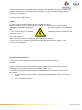
GM Manufacturing Poland Sp. z o. o. Gliwice Project Flex Cell RFQ For Spot Welding System Rev. 1 – 02.06.2014 Created by M. Cieszynski General This specification is for Automatic Spot Welding System with Auto adaptive regulation mode. General Motors Manufacturing Sp. z o. o. reserved rights to performer Equipment Buy-off before release it to manufacturing process. Only 1 unit. Delivery time: September 2014 Contact person: Marcin Cieszynski Phone: +48 32 270 99 83 Mail: [email protected] Radoslaw Kolassa Phone +48 728 417 369 Mail : [email protected] Content of Specification This equipment technical specification is intended as a guide for quoting purposes. All items specified are intended as a minimum standard acceptable to GM Manufacturing Poland (GMMP). In no case is the successful contractor to assume the specification relieves him of the responsibility for the proper function of the equipment. The supplier, in submitting the bid, guarantees the functionality of the equipment. Any changes to the specifications that are initiated by GMMP will be issued in writing in the form of addendum. THE FULL LIST OF THE COMPONENTS TO BE UTILIZED BY THE SUPPLIER MUST BE PRESENTED TO THE GM. The following prints or specifications are included in this packet for quotation purposes: 1. 2006/42/EC Machine Directive - CE Certification, 2. 2004/108/EC ECM Directive - CE Certification, 3. 4. 5. 6. 7. 8. 9. ISO 9001 NFPA 70 (2008), National Electrical Code. NFPA 79 (2007), Electrical Standard for Industrial Machinery. SAE HS-1738, Electrical Standard for Industrial Machinery – Supplement to NFPA 79. GM GCCB-1, Global Common Controls Build Standards. GM GCCH-1, Global Common Controls Hardware Design Standards. GM GRS-4 B1, Global Robot Specifications, Section B1:Resistance Welder Control Interface 10. EN 50240, Electrical Design of Welding Equipment 11. All other applicable local, state, national, international laws Scope This specification describes the hardware, software, and functionality required for a welder control used for resistance welding applications. Purpose This specification provides the manufacturer of welder controls with the specific requirements Created by M. Cieszynski for a DC inverter welder control for spot and projection welding applications. Definitions A: ampere CCC: China Compulsory Certification CE: Conformité Européene" which literally means "European Conformity" CSA: Canadian Standards Association DEP: Data Entry Panel DHCP: Dynamic Host Configuration Protocol ECTC: Equivalent Continuous Thermal Current FTP: File Transfer Protocol GCCL: GM Global Common Components List IEC: International Electrotechnical Commission l/min: liters per minute I/O: Input/Output kA: kilo-ampere LED: light emitting diode MFDC: Medium Frequency Direct Current ms: millisecond NFPA: National Fire Protection Association N.C.: Normally Closed NIST: National Institute of Standards and Technology ODVA: Open DeviceNet Vendors Association PCHMI: Personal Computer Human Machine Interface PE: Protected Earth See definition of Ground. RWMA: Resistance Welder Manufacturer’s Association UL: Underwriters Laboratory VAC: Voltage Alternating Current VDC: Voltage Direct Current Manufacturer Requirements General 1. All welder controls and the electronic switch enclosure shall conform to CE Mark, CCC, CSA. 2. The manufacturer shall provide an electronic service manual suitable for use by plant maintenance personnel. The service manual shall contain required safety precautions for working on the power section, descriptive literature, photographs, replacement part information on all components, wiring diagrams, and any other information pertinent to operating, troubleshooting and maintaining the welder control. This manual shall be Created by M. Cieszynski provided in English and the language of the installation site. 3. The plant receiving the welding system shall be furnished with one electronic copy. The cover page of the electronic manual shall readily indicate the manufacturer and model number of the welder control. 5. Where applicable, commercial part numbers shall be listed in the service manual. System Requirements 1. There shall be two welder control versions for incoming voltage ranges: 380 to 400 VAC. 2. The welder control shall be capable of operating on voltages ranging from 380 to 400VAC ±10% with drops of up to 20% (for a duration of 350ms) of the rated incoming voltage, and at a frequency of either 50 or 60Hz. Software shall be capable of selecting incoming voltage, and any hardware changes required to switch between incoming voltages shall be done through hardwire jumpers. When shipped from the OEM, the welder control shall be clearly marked to easily identify the voltage that the particular welder control is wired for. 4. The output frequency of the inverter shall be 1000Hz. 5. The welder controls shall be designed to operate over an ambient operating temperature range of 10 C degree to 50 C degree. 6. All components subject to revision shall have a means of indicating the present revision number. 7. The interface to the welder control for all applications shall be provided via an Ethernet communications link. Signal definitions for global robotic and tooling Ethernet welder controls are defined in GRS-4B1, and the connectors used for the Ethernet communication are specified in Section 7. Additional welder control signals are defined in section 10. 8. Circuit breakers shall be used for protection of all electrical components within the welder control panel except where interrupting ratings are insufficient. Warranty 1. The warranty shall begin when the welder control is shipped from the manufacturer. The warranty shall continue for six years on power components, (e.g., breaker, contactor, IGBT), and five years for all other components: After the start of production (SOP) on new equipment installations or At shipment from the manufacturer on current equipment installations 2. Defects shall be corrected expeditiously at the supplier’s expense at a GM designated facility. 3. Welding equipment software “bug” fixes shall be provided to GM and installed free of charge throughout the life of the welding equipment. Removable media and documentation shall be provided to each affected site and the designated CCRW representative. Electrode Cap Dresser and Cutter Blade Requirements General 1. All components for the welder control shall be housed in one enclosure. 2. All welder control enclosures shall be IEC IP54. 3. Any welder control that includes internal water-cooled devices shall also include two 12mm drain holes. Created by M. Cieszynski 4. All components and conductors within the welder control utilized in the primary feed from the main circuit breaker to the inverter shall be capable of carrying the rated continuous load of the main circuit breaker. 5. All fasteners shall be metric. 6. All dimensions shall be metric. Labeling All welder controls shall be labeled. One set of labels shall be in English and when the native language is not in English, an additional set of labels shall be installed with equivalent messages in site. the native language of the installation 1. One stored energy label (RWMA 156103G) shall be installed near the main disconnect. 2. The water outlets shall be clearly identified as "Water In" and "Water Out" using adhesive labels that are permanently installed to the outside of the enclosure. 3. One warning sign, graphical symbol 60417-2-IEC-5036, shall be plainly visible on the enclosure door. Example: Communication Connections 1. All Ethernet connectors shall be M12 to RJ45, female, CAT5E, Unshielded, Stranded. 2. There shall be an individual Ethernet connector for every timer in the enclosure. Each connector shall be uniquely labeled using metal or adhesive labels that are permanently installed on the outside of the enclosure,(i.e. ENET1, ENET2, etc.). 3. Auxiliary power shall be supplied through a CENELEC connector (used for the No Control Stop signal). Pin one (+24 V DC) “Output Power” provides the “Enable Motion” signal to the welder control. Pin four (0 V DC) “Common”. Created by M. Cieszynski Software Standard Mode (CCR) Welding Feature Requirements Constant current shall maintain a constant weld current within ±1% during changes in either the primary or secondary welding circuits. The constant current feature shall return the weld current value to within 3% of the programmed value within 10ms or less for weld current disturbances of up to 20%. There shall be an indication (e.g., an alert or fault) when the operating range of weld current compensation is exceeded. Adaptive Welding Feature Requirements 1. Software shall be capable of welding ranges of steel thickness using one schedule. Ranges for the determining metal thickness per schedule are: a. 0.65 mm to 1.40 mm at 2.6 kN b. 1.41 mm to 2.3 mm at 4.0 kN 2. There shall be programmable maximum allowable values for extending the weld time and raising or lowering the current. Stepper Requirements Minimum Functionality 1. The stepper shall be capable of providing functionality to one or all of the available weld schedules. The counters shall be: available to multiple stepper boosts able to be assigned to any or all schedules assignable to any group Created by M. Cieszynski 2. The stepper shall increment one count upon the successful completion of any weld schedule assigned to it. 3. A minimum of 5 programmable steps shall be permitted. 4. A minimum of 0 and a maximum of 9999 counts shall be available in each step. 5. The stepper’s status shall be indicated, including: a. stepper on/off b. present step number c. weld count d. preset count e. percent current in that step for the stepper displayed 6. Ability to advance any stepper to the next step by both the DEP and network software. 7. An alert message for “Cap Change Request” and “Approaching Cap Change” functions shall be provided. 8. When the stepper reaches the end of the programmed counts, the “Cap Change Request” output shall turn “on” and the “No Alert” output shall turn “off” while still allowing further weld initiations. After an additional 40 welds are completed, the “No Fault” output turns “off” and further welding is prohibited. 9. If the programmed current setting is decreasing from one step to the next during the input of stepper parameters, a warning shall be displayed. 10. The steppers shall be a “ramp” type and continually increase current. 11. Stepper current increases (or boosts) to base schedule shall have the capability of being programmed in amps. Resolution to be in 10A increments. 12. All weld current-dependent functions (e.g., constant current and low primary current faults) shall automatically adjust to track stepper settings. 13. The maximum programmable number of tip dresses shall be 9999. Resetting Steppers 1. The Caps Changed input shall be capable of resetting the weld counts and tip dress counts in two ways: a. All steppers shall be reset if a Caps Changed input is received with no binary bits on. Steppers Reset output shall turn on when all steppers are reset and shall stay on until any stepper count increases. Note: All steppers shall also be resettable by both the DEP and network software. b. A single stepper shall be reset when a binary bit pattern is turned on and then a caps changed input is received. The binary number will indicate which electrode shall be reset. The welder control shall send out the stepper number that was reset through a binary bit pattern and also turn on Steppers Reset output when the stepper is reset and shall stay on until any stepper count increases. I/O Weld Controller Signal Definitions Robot / PLC Inputs (Weld Controller Outputs) Created by M. Cieszynski 1. No Alert: A signal (normally high) indicating that no alerts are present. When an alert is present, the welder control shall continue to operate. The ‘No Alert’ signal stays “off” until the ‘Fault Reset’ signal is “on” or the condition that prompted the alert does not appear upon initiation of the next weld. 2. No Fault: A signal (normally high) indicating that no faults are present. If the cause of the fault has not been removed after the ‘Fault Reset’ input has been received, the weld controller shall reassert the fault after the release of the ‘Fault Reset’ signal. If a fault(s) is present, the welder controller shall not cycle until all faults are cleared. 3. Weld Mode On: When high, this signal indicates the weld controller is in the weld mode and will pass current. The robot shall check this signal prior to an initiate weld, and it shall not review the signal during that weld. The robot shall compare this signal to its output (weld mode) to confirm that the weld controller is in the correct mode. 4. Process Complete: A signal, when high, indicating the requested schedule has been completed and no faults were generated. This signal shall function in ‘no weld’ mode. This signal shall remain high until the ‘Initiate Weld signal drops. 5. Schedule In Progress: A signal, when high, indicating a schedule is being executing. This signal drops low again after a ‘Process Complete’ signal or a fault is detected. This signal is a response to an initiate signal. While ‘Schedule In Progress’ is high and a schedule is being executed, the weld mode from the robot shall be ignored by the weld controller. 6. Stepper Reset Gun 1, 2, 3, 4: Individual signals indicating that the requested steppers are reset. The robot shall communicate this signal for SWC X to the cell controller via the ‘Process X Alert 2’ output. 7. Approaching Cap Change Gun 1, 2, 3, 4: Individual signals indicating an alert from the weld control that one or more of the steppers are approaching cap change or the maximum number of tip dresses has been achieved. 8. Tip Dress Request Gun 1, 2, 3, 4: Individual signals indicating the weld controller is requesting a tip dress. The weld controller shall set this signal after a successful weld, in conjunction with ‘Process Complete’, in which the stepper has entered the preset step number defined for requesting a tip dress. This request shall not inhibit further welding cycles. 9. Cap Change Request Gun 1, 2, 3, 4: Individual signals indicating a request from the weld controller to perform a cap change on a particular gun. The weld controller shall only set a ‘Cap Change Request’ after a successful weld. This request shall not inhibit further welding cycles (within a preset limit) or indicate a fault to the robot controller. 10. Pressure Bits (1, 2, 4, 8): The robot controls the gun pressure based on a table with 255 entries, one for each weld schedule. A weld pressure table shall be maintained in the robot through reading the pressure bits from the weld control. The robot shall initially populate the pressure table with invalid pressures. During a normal weld sequence, the robot shall update the weld pressure Created by M. Cieszynski entry for the schedule used after the ‘Schedule in Progress’ has been set but before ‘Initiate Weld’ goes low. The weld controller shall hold the binary pressure outputs high for the selected schedule as long as either the ‘Initiate Weld’ or ‘Request Pressure’ is high. 11. Read Pressures: A signal indicating that the pressure bits shall be read by the robot. Upon executing a schedule with an invalid pressure, the robot shall first update the pressure table entry for that schedule prior to the weld using the Request Pressure - Read Pressures handshaking. 12. Quality Stop: A signal that indicates while welding in adaptive mode there have been multiple adaptive faults while welding a part. The fault resets with the Fault Reset input but the internal counter does not reset until End of Part is received. 13. Adaptive Regulation Off: A signal indicating that a schedule programmed as adaptive and the regulation is turned off in the control will indicate the weld control is not regulating the weld. This signal will turn off at the initiation of the next weld. If a schedule is not adaptive this signal will stay low. 14. Adaptive Monitoring Off: A signal indicating that a schedule programmed as adaptive and the monitoring regulation is turned off in the control will indicate the weld control is not monitoring the weld. This signal will turn off at the initiation of the next weld. If a schedule is not adaptive this signal will stay low. 15. End of Part Reply: A signal indicating the End of Part signal from the robot/PLC was received and the quality counter has been reset. Signal will stay until End of Part signal from robot/PLC drops. 16. Adaptive Capable: A signal to indicate the weld control has the ability to initiate adaptive weld schedules. Signal shall be high at all times. 17. Contactor Open: A signal indicating that the isolation contactor in the weld controller is in the open state. It is not necessary to monitor this signal at the robot. In the weld controller, this signal is a pass-through from the isolation contactor auxiliary contact block. 18. Not Control Stopped: A signal indicating the weld controller is not in a control stopped state. The signal shall be based on the status of the hardware affected by the 24V Control Stop input to the weld controller. The robot shall communicate this signal for SWC 1 and 2 to the cell controller via the ‘Process Equipment Not Control Stopped’ output. Robot / PLC Outputs (Weld Controller Inputs) 1. Binary Select Bits (1, 2, 4, 8, 16, 32, 64, 128, 256, 512, 1024, 2048, 4096, 8192, 16384, 32768, 65536, 131072, 262144, 524288): Selects a weld schedule using binary numbering. Schedules 1 through 255 will be selected directly through these bits and disregards the Weld Body ID bits. Everything above 255 will be used to indirectly select schedules 1 through 255. When the binary selection is above 255 the Weld Body ID bits also need to be set. These bits shall be “on” at the same time or before an “initiate weld” or “request pressure” input is received. Created by M. Cieszynski 2. Weld Body ID Bits (1, 2, 4, 8, 16, 32, 64, 128): Sends the body style bits from the PLC to the weld control. These bits can be on before the binary select and stay on during the complete welding sequence. 3. Initiate Weld: A signal used to initiate the weld schedule after a binary selection. 4. Weld Mode: A signal indicating a request of weld mode to the weld controller. The weld mode from the robot shall be read by the weld controller upon an initiate (and not reviewed until ‘Process Complete’). If ‘Weld Mode’ is low and a weld is initiated, the weld controller shall execute a normal weld sequence with the exception of passing current and with the isolation contactor open. If the robot detects a mismatch between this signal and the ‘Weld Mode’ input, a process fault shall be indicated. 5. Fault Reset: A signal that resets the weld controller faults. If the cause of the fault has not been removed, then the weld controller shall reassert the fault after the release of the ‘fault reset’ signal. 6. Enable Contactor Saver: A signal that, when high, indicates to the weld controller to hold the contactor closed for the time configured in the weld controller. This signal does not have to be asserted to initiate a weld. If ‘Enable Contactor Saver’ is low at the end of a schedule, the contactor shall be opened. The weld control shall not have any faults or alerts associated with this item. If this signal goes low after a successful weld but prior to the isolation contactor saver timer timing out, the weld controller shall open the contactor immediately. 7. Stepper Reset Gun 1, 2, 3, 4: A signal to the weld controller indicating that a particular weld gun stepper shall be reset. This output shall remain on until the “Stepper Reset Gun X” is received form the weld controller. Note: The tips dressed indication shall be made through the use of schedules to the weld controller. Schedules 247 through 254 are used for signaling that the respective tip has been pre-dressed or dressed. Two weld schedules are reserved per weld gun. (i.e. schedule 247 for gun 1 pre-dress and schedule 248 for gun 1 dress). 8. Request Pressure: A signal to the weld controller indicating that the weld controller shall set the weld pressure bits for the current binary schedule. It is not used in normal weld sequences. 9. Part Finished: A signal to indicate to the weld controller all weld spots on a part are complete. 10. Gun Resistance Check: A signal to indicate to the weld controller the next initiate will be testing the resistance of the weld gun without metal. If the schedule fails the resistance check the Quality Stop signal will turn on and the No Fault signal will drop. Weld schedules used for Gun Resistance check are 243 through 246. 11. Re-weld/Turn off Adaptive: A signal to the weld controller to turn off adaptive regulation and monitoring. Created by M. Cieszynski 2.3 Hardwire Outputs (Weld Controller Inputs) 1. Control Stop: When “on”, the welder control is allowed to operate. When “off”, the control shall immediately stop all welds and open the isolation contactor. The welder controller shall perform a safe and orderly shutdown, stopping all welding current within one line cycle. 2. Transformer Overtemp: When “on”, indicates that the transformer is operating within its temperature range. When “off”, will not allow initiation of the weld schedules and annunciate a fault. However, if it turns “off” during a weld schedule, the weld schedule will be completed and the fault will be set, prohibiting further welding. Note: this input is typically wired to the weld controller only in the case of manual welding. END. Created by M. Cieszynski