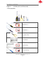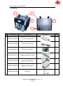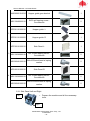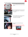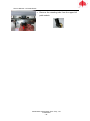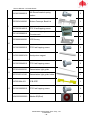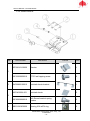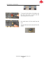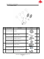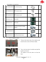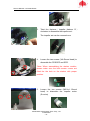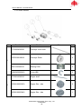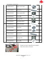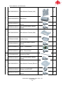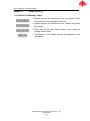
1
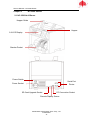
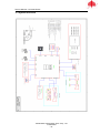
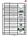
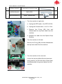
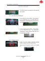
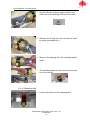
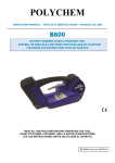
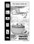
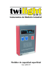
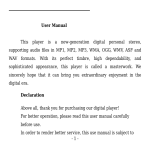
NC-3500 Series Multi Currency Banknote Counter Service Manual Document Version 1.0 May 26th, 2013 Masterwork Automodules Tech Corp Ltd. 11F-3, 3, Park St., Nangang, 11503, Taipei, Taiwan [email protected] COPYRIGHT © 2013 Masterwork Automodules Tech Corp Ltd. All rights reserved. This Document or any part thereof may no, without the prior written consent of Masterwork Automodules Tech Corp Ltd., be copied, reprinted or reproduced in any material form including, but without prejudice to the foregoing and not by way of exception photocopying, transcribing, transmitting or storing in any medium or translating into any language, in any form or by any means, including but not limited to, electronic, mechanical, xerographic, optical, magnetic, digital or other methodology. Ji3fm4a93 Service Manual – NC-3500 Series CONTENT CHAPTER 1 INTRODUCTION .......................................................................................... 4 1.1 ABOUT NC-3500 SERVICE MANUAL ............................................................................................................. 4 1.2 IMPORTANT SAFETY PRECAUTION .................................................................................................................. 4 1.3 ABBREVIATIONS AND ACRONYMS .................................................................................................................. 4 1.4 CONTACT INFORMATION .............................................................................................................................. 5 CHAPTER 2 NC-3500 OUTLINE ...................................................................................... 6 2.1 NC-3500 AT A GLANCE ............................................................................................................................. 6 2.2 SPECIFICATION ........................................................................................................................................... 7 2.2.1 Functional and Mechanical Specification ...................................................................................... 7 2.2.2 Electrical Specification ................................................................................................................... 7 2.2.3 Interface Specification ................................................................................................................... 8 2.2.3.1 Thermal Printer (RS-232) ....................................................................................................... 8 2.2.3.2 Remote Display ...................................................................................................................... 9 2.2.3.3 PC .......................................................................................................................................... 9 2.3 SYSTEM OVERVIEW .................................................................................................................................. 10 CHAPTER 3 MAINTENANCE......................................................................................... 11 3.1 CLEANING THE COVER OF NC-3500 ............................................................................................................ 11 3.2 CLEANING THE BILL PATH OF NC-3500 ......................................................................................................... 11 CHAPTER 4 MAINTENANCE MODE ............................................................................. 12 CHAPTER 5 NC-3500 PART LIST AND DISASSEMBLY .................................................... 13 5.1 TOOL PREPARATION .......................................................................................................................... 13 5.2 HOUSING ............................................................................................................................................... 14 5.2.1 Side Panel Left and Right ............................................................................................................. 15 5.2.2 Top Cover-Upper and Lower ........................................................................................................ 17 5.2.3 Hopper guide set ......................................................................................................................... 19 1.3.1 Back Housing Module ............................................................................................................ 21 1.3.2 Upper Bill Path Module .......................................................................................................... 23 5.3.1.1 Upper Bill Path Plate .................................................................................................... 28 5.3.1.2 NC3500 PCB -S board ................................................................................................... 28 5.3.1.3 NC3500 PCB -IRTR Board .............................................................................................. 29 5.3.1.4 Magnetic sensor ........................................................................................................... 29 5.3.1.5 Retarding Wheel Module ............................................................................................. 30 5.3.1.6 Retarding Idler .............................................................................................................. 31 5.3.2 Control Panel Module .......................................................................................................... 33 Masterwork Automodules Tech. Corp., Ltd Confidential -2- Service Manual – NC-3500 Series 5.3.2.1 NC3500 PCB-UI Board .................................................................................................. 34 5.3.2.2 NC3500 PCB - IRR Board ............................................................................................... 35 5.3.3 Bottom Conveyor Module ..................................................................................................... 36 5.3.4.1 NC3500 PCB -IRTE Board ..................................................................................................... 40 5.3.4 Stacker Module ...................................................................................................................... 41 5.3.5 Impeller Module .................................................................................................................... 45 5.3.5.1 5.3.6 Roller Module ........................................................................................................................ 48 5.3.6.1 5.3.7 Roller module ............................................................................................................... 49 Base Module .......................................................................................................................... 50 5.3.7.1 CHAPTER 6 Impeller module ........................................................................................................... 46 Base module ................................................................................................................. 53 TROUBLE SHOOTING ................................................................................ 55 6.1 DEFINITION OF MESSAGE CODES ................................................................................................................. 55 APPENDIX A REVISION HISTORY ................................................................................... 56 Masterwork Automodules Tech. Corp., Ltd Confidential -3- Service Manual – NC-3500 Series Chapter 1 Introduction 1.1 About NC-3500 Service Manual This manual is for the maintenance of NC3500 and it includes the disassembly process, spare part replacement, basic inspection and repair. 1.2 Important Safety Precaution NC-3500 is exclusively for indoor usages only, please do not use or install it outdoor. Please check the adaptor and power cord periodically to protect from any damages. The power source is between AC 100 - 240V, 50/60 Hz. Keep NC-3500 away from magnets, activated cellular phones, electrical appliances, or speakers within 13 cm/ 5 inches. Please disconnect power adaptor and remove batteries when the machine left unused for a long time. NC-3500 is designed for notes processing. Please process banknotes ought to be verified in the four orientations (“Head Up-Right”, “Head Reversed”, “Tail Up-Right” or “Tail Reversed”). 1.3 Abbreviations and Acronyms IR MA MB MG MR MT Infrared Masterwork Automodules Megabyte Magnetic Magnetoresistive Metal Thread PC USB UV Personal Computer Universal Serial Bus Ultraviolet Masterwork Automodules Tech. Corp., Ltd Confidential -4- Service Manual – NC-3500 Series 1.4 Contact Information Masterwork Automodules Tech Corp Ltd. www.automodules.com Address: 11F-3, 3, Park St, Nangang, 11503, Taipei, Taiwan Tel: Fax: +886 2 2655 7997 +886 2 2655 7996 Email: [email protected] Masterwork Automodules Tech. Corp., Ltd Confidential -5- Service Manual – NC-3500 Series Chapter 2 NC-3500 Outline 2.1 NC-3500 At A Glance Hopper Guide Hopper 2.8 LCD Display Stacker Pocket Power Switch Serial Port Printer Power Socket SD Card Upgrade Socket PC Connection Socket Remote Display Socket Masterwork Automodules Tech. Corp., Ltd Confidential -6- Service Manual – NC-3500 Series 2.2 Specification 2.2.1 Functional and Mechanical Specification Sensors: IR Array, MR, UV Denomination Detection: Available Currencies IR Transmission USD, EUR, and up to 5 additional currencies 60 x 85 x 0.08 mm - 100 x 190 x 0.12 mm 500 notes (circulated notes) 200 notes (circulated notes) Countable Note Size: Hopper Capacity: Stacker Capacity: Display: Display Language: Feed System: Piece Count Speed: Denomination Count Speed: Dimensions (mm): 2.8 Inch LCD English or Customized Roller friction system 1000/ 1200/ 1500 notes/min. (selectable) 900, 1200, 1500 notes/min Weight: Options: Approx. 7.2 kg Remote Display / Thermal Printer 285 (W) x 270 (D) x 280 (H) 2.2.2 Electrical Specification Power Supply: 100-240V AC, 50/60Hz Power Consumption: Max. 40W Masterwork Automodules Tech. Corp., Ltd Confidential -7- Service Manual – NC-3500 Series 2.2.3 Interface Specification 2.2.3.1 Thermal Printer (RS-232) (A) Communication Conditions Item Specification Standard: Baud Rate: Synchronous Method: Data Format: Start Data EIA RS-232C 9600bps ,38400bps ,115200bps Asynchronous 1 bit 8 bits Parity Stop Connector: Cable length: None 1 bit D-sub 9pin (male) 15 m max (B) Interface Connector - Equipment Side Connector Pin NO. Signal Direction 1 2 ─── ─── ─── ─── 3 TXD 4 5 4 7 8 9 ─── GND ─── ─── ─── ─── NC3500→thermal Printer ─── ─── ─── ─── ─── ─── Masterwork Automodules Tech. Corp., Ltd Confidential -8- Service Manual – NC-3500 Series 2.2.3.2 Remote Display (A) Communication Conditions Item Specification Standard: Baud Rate: Synchronous Method: Data Format: Start Data Parity UART 115200bps Asynchronous 1 bit 8 bits None Stop Connector: Cable length: 1 bit Mini USB 5 pins (female) 1.5m max (B) Interface Connector - Equipment Side Connector Pin NO. Signal Direction 1 2 3 VCC VCC RXD ─── ─── ─── 4 TXD 5 GND NC3500→Remote display ─── 2.2.3.3 PC Item Data Communication Port Specification USB Masterwork Automodules Tech. Corp., Ltd Confidential -9- Service Manual – NC-3500 Series 2.3 System Overview Masterwork Automodules Tech. Corp., Ltd Confidential - 10 - Service Manual – NC-3500 Series Chapter 3 Maintenance 3.1 Cleaning the Cover of NC-3500 Prepare a mixture of a gentle kitchen-use detergent (one that does not contain abrasive powder or strong chemicals such as acid or alkaline.) Use 5 parts water to 1 part detergent. Absorb the diluted detergent into a sponge. Squeeze excess liquid from the sponge. Wipe the cover with the sponge, use a circular motion and take care not to let any excess liquid drips into the interior of the device. Wipe the surface to remove the detergent. Rinse the sponge with clean running water. Wipe the over with the clean sponge. Wipe the surface again with a dry, soft lint-free cloth. Wait for the surface to dry completely and remove any fibers. 3.2 Cleaning the bill path of NC-3500 Open the bill path. Gently wipe it or dust the bill path with a MA brush or a dry, soft lint-free cloth. If stains remain, moisten a soft, lint-free cloth with water or a 50-50 mixture of isopropyl alcohol and water that does not contain impurities. Wring out as much of the liquid as you can. Wipe the bill path and the sensor surface again; do not let any liquid drip into the device. Repeat 1-5 to clean the conveyer path. *NOTE: Avoid spraying cleaner directly on the device, and be sure to day the bill path before closing it. Masterwork Automodules Tech. Corp., Ltd Confidential - 11 - Service Manual – NC-3500 Series Chapter 4 Maintenance Mode Masterwork Automodules Tech. Corp., Ltd Confidential - 12 - Service Manual – NC-3500 Series Chapter 5 NC-3500 part list and Disassembly 5.1 Tool preparation Screwdriver (+) Screwdriver (-) Long Nose Pliers 7 mm Wrench 3 mm Hex Key 1.5 mm Hex Key Masterwork Automodules Tech. Corp., Ltd Confidential - 13 - Service Manual – NC-3500 Series 5.2 Housing 2 1 2 3 4 No. 1 Part Number Part Name 4PP02010120010 Top cover- upper part 1 4PP02010120020 Top cover- lower part 1 4SC10030080210 Ø 3*8 Countersunk 10 3PP52500100170 Hopper guide gear holder 1 4PP92610100010 Hopper guide holder-L 1 4PP92610100020 Hopper guide holder-R 1 3GE00814261100 Gear-14T 1 Masterwork Automodules Tech. Corp., Ltd Confidential - 14 - Picture Unit Service Manual – NC-3500 Series 4NC90800120010 Hopper guide gear bracket 1 4SC13040060210 Ø 4*6 self tapping screw Countersunk 2 3PP92110100010 Hopper guide- L 1 3PP92110100020 Hopper guide- R 1 4PP32010100010 Side Panel-L 1 4SC13030080210 Ø 3*10 self tapping screw Countersunk 2 4SC90040100210 M4x10-Round head w/ spring washer 2 4PP42010100010 Side Panel-R 1 4SC13030080210 Ø 3*10 self tapping screw Countersunk 2 4SC90040100210 M4x10-Round head w/ spring washer 2 2 3 4 5.2.1 Side Panel Left and Right 1. Left side Prepare the machine and all the necessary tools. Right side Masterwork Automodules Tech. Corp., Ltd Confidential - 15 - Service Manual – NC-3500 Series 2. Turn the machine to bottom side and loosen the four screws (M4x10-Round head w/ spring washer) 3. Open the upper bill path and loosen the screw (Ø 3*10 self tapping screw – Countersunk) on the right side. 4. Turn the machine to the front side and loosen the screw (Ø 3*10 self tapping screw – Countersunk) on the stacker. 5. Disassemble the Side Panel-R from the machine. *Note: When assembling the side cover, please make sure the plastic cover and metal plate fitted to each other. Masterwork Automodules Tech. Corp., Ltd Confidential - 16 - Service Manual – NC-3500 Series 6. Repeat the steps 1 to 5 to dismount the Side Panel-L. *Note: Please notice the same as above when assebling the side panel-L. 5.2.2 Top Cover-Upper and Lower 1. Loosen the screw (Ø 3*8 self tapping screw –Countersunk) on the right side of top cover. 2. Loosen the screw (Ø 3*8 self tapping screw –Countersunk) on the left side of top cover 3. Loosen the two screws (Ø 3*8 self tapping screw –Countersunk) on the back side of top cover Masterwork Automodules Tech. Corp., Ltd Confidential - 17 - Service Manual – NC-3500 Series 4. Disassemble top cover- upper part from the machine. 5. Open the upper bill path and loosen the two screws (Ø 3*8 self tapping screw – Countersunk) on the right side. 6. Open the upper bill path and loosen the two screws (Ø 3*8 self tapping screw – Countersunk) on the left side. 7. Disassemble top cover- lower part from the machine. *Note: When assembling the top covers, please make sure the two plastic latches fitted to the upper cover Masterwork Automodules Tech. Corp., Ltd Confidential - 18 - Service Manual – NC-3500 Series 5.2.3 Hopper guide set 1. Loosen the two screws (Ø 3*8 Countersunk) on the top of hopper guide set. 2. Disassemble hopper guide set from the machine. 3. Loosen the two screws (Ø 4*6 self tapping screw - Countersunk) on the back side of hopper guide set. 4. Disassemble hopper guide gear bracket from the hopper guide set. The gear and hopper guide holders can be disassembled directly. *Note: When assembling the hopper guide holders, please move the hopper guide holders to the very end of the gear holder then place the gear onto the central pole. Masterwork Automodules Tech. Corp., Ltd Confidential - 19 - Service Manual – NC-3500 Series 5.3 Total Assembly Masterwork Automodules Tech. Corp., Ltd Confidential - 20 - Service Manual – NC-3500 Series 1.3.1 Back Housing Module No. 1 Part Number Part Name Picture Unit 4PP22010120010 Back Lid 1 4OC22240000300 Power supply bracket 1 4OC22240000200 Power Switch 1 4SC10030080210 M3×8 - Countersunk 2 4SC90030060210 3x6-Round head w/ spring washer 4 4OP351006-001 PCB COM 1 4SC33030050210 ST3*6 self tapping screw 1 2 Masterwork Automodules Tech. Corp., Ltd Confidential - 21 - Service Manual – NC-3500 Series 1. Turn the machine to right side Loosen the two screws (3x6-Round head w/ spring washer) on the back lid 2. Turn the machine to left side Loosen the two screws (3x6-Round head w/ spring washer) on the back lid 3. Disassemble the back lid from the machine. a c b a. Unplug the power connector (Red and Black wire) on the power supply b. Unplug the(A to COM 16*290)COM board cable c. Unplug the ground cable (Yellow-Green) from power supply bracket. Do not unplug from the other side of ground line. It may damage the joints on switch power. *Note: Do not pull away the back lid until unplug the connected cables. Masterwork Automodules Tech. Corp., Ltd Confidential - 22 - Service Manual – NC-3500 Series 4. Loosen the screw (ST3*6 self tapping screw) on the COM board. Turn to the other side of back lid; Use the pliers to loosen the two hex screws of 9-pin USB connector. The PCB COM can be removed from the back lid. 1.3.2 Upper Bill Path Module No. 1 Part Number Part Name 4TP00008030040 Top Module Axis 1 4TP10816060010 Top frame shaft sleeve (8-16) 2 4WA60600000010 E-ring (Ø 6) 4 Masterwork Automodules Tech. Corp., Ltd Confidential - 23 - Picture Unit Service Manual – NC-3500 Series 4NC90803000010 Top Frame 1 4TP20000030030 Gap Adjustment Screw M8 (P0.5) 1 4TP10608030010 Top Module Latch 2 4WA60400000010 E-ring (Ø 4) 2 4TP20000030020 Gap adjustment disc 1 4SP31140210010 Gap adjustment screw spring 1 4TP20000030010 Gap adjustment screw bracket 1 4SP01150070010 Spring for retarding module Torsion (1.5-Ø 14) 1 4TP00012030010 Retarding wheel shaft 1 4NC51500120010 Retarding wheel bracket 1 4TP10816060010 Top frame shaft sleeve (8-16) 2 4SC80050160210 M5x16 - hex socket 1 4SC90030100210 M3x10-Round head w/ spring washer 2 4SC90040100210 M4x10-Round head w/ spring washer 4 2 Masterwork Automodules Tech. Corp., Ltd Confidential - 24 - Service Manual – NC-3500 Series 3 4 4NU00403002010 M4 hex screw 4 4SC80040100210 M4x10 - hex socket 2 4TP00008030030 Retarding wheel shaft 1 3RPA3100220010 Retarding wheel 2 4PP52620100020 Feeder idler bracket 1 4PP52610100010 Feeder idler 1 4BE01220880010 Bearing 685 2 4TP00005021020 Feeder idler shaft 1 4TP10610600220 Clutch bearing holder 1 BEHF0612R01010 Clutch bearing, HF0612R 1 4BE01220840010 Bearing F688 1 4WA60600000010 E-ring (Ø 6) 1 4WA60400000010 E-ring (Ø 4) 1 4WA60300000010 E-ring (Ø 3.2) 2 4SC80030080210 M3x6 Socket set screw 4 4PP52610100020 Retarding idler holder 1 4TP00005030020 Retarding idler shaft 1 4BE01190560010 Bearing 635 2 Masterwork Automodules Tech. Corp., Ltd Confidential - 25 - Service Manual – NC-3500 Series 4SP01080040010 Upper bill path idler spring - L 1 4SP01080040020 Upper bill path idler spring - R 1 4SC90030060210 3x6-Round head w/ spring washer 1 4PP92010100020 Magnetic sensor housing 1 MG000203B001 Magnetic sensor 1 4SP011200700010 Spring for magnetic sensor 4 5 4SC33030140220 3x14 - self tapping screw w/ washer 4 4PP52510100010 Upper Bill Path 1 4PP92610100030 Retarding idler holder-L 2 4PP92610100040 Retarding idler holder-R 2 4SP01080040030 Upper bill path idler spring 2 4BE01220860020 Bearing 698 w/PU ring 2 4WA00800000010 φ8.*0.5t (Cooper) 4 4OP351005-001 PCB-S 1 4SC00030060210 M3x6 - Round head 4 3PP52400000160 Transmission receiver bracket 1 6 7 Masterwork Automodules Tech. Corp., Ltd Confidential - 26 - Service Manual – NC-3500 Series 8 3PP82400000070 Transmission receiver mask 1 4OP351003-001 PBC-IRTR 1 4SC00030060210 M3x6 - Round head 6 9 1. Turn the machine to right side. a. Unplug the IRTR cable(A to IRTR 18*230) b. Unplug the S board cable(A to S 11*180) c. Remove the E-ring (Ø 6) first and disassemble the top frame shaft from the machine d. Release the cable from the Square Snap Bushing 2. Turn the machine to left side. Remove the E-ring (Ø 6) first and disassemble the top frame shaft from the machine 3. Turn the machine to the rear side Loosen the screws (M3x6-Rround Head with spring washer) on the both sides of base plate and disassemble the ground cables from the machine. Masterwork Automodules Tech. Corp., Ltd Confidential - 27 - Service Manual – NC-3500 Series 4. The upper bill path module is free to be removed from the machine. 5.3.1.1 Upper Bill Path Plate 1. Turn the upper bill path module and have the sensor side up. Loosen the two screws (ST3*10 self tapping screw) on the right side of the module. 2. Turn the upper bill path module to the other side and Loosen the two screws (ST3*10 self tapping screw) Then the upper bill path can be removed from the module. 5.3.1.2 NC3500 PCB -S board 1. Release the cables from the connecters. 2. Loosen the four screws (ST3*10 self tapping screw) on the PCB-S board and remove the two ground cables. *Note: When plugging in the cable on the Masterwork Automodules Tech. Corp., Ltd Confidential - 28 - Service Manual – NC-3500 Series connecters, please make sure all the pins are well connected on the cable. 3. The PCB-S board is removed from the upper bill path module. 5.3.1.3 NC3500 PCB -IRTR Board 1. Loosen the four screws (M3x6 - Round head) on the PCB-IRTR board. The PCB-IRTR with Transmission receiver bracket can be pull out from the bill path directly. 2. Loosen the two screws (M3x6 - Round head) on the PCB-IRTR board. The underneath Transmission receiver bracket and mask can be separated from PCB. 5.3.1.4 Magnetic sensor 1. Loosen the four screws (3x14-self tapping screw w/ washer) on the bill path board. The housing of magnetic sensor can be pulled off. Masterwork Automodules Tech. Corp., Ltd Confidential - 29 - Service Manual – NC-3500 Series 2. Push the sensor and housing from opposite direction to dissemble the sensor. 5.3.1.5 Retarding Wheel Module 1. Turn the retarding wheel module to rear side and use pliers to remove the Spring Torsion (1.5-Ø 14) from the hook. 2. b Turn the retarding wheel module to left side a. Remove the E-ring (Ø 4) first and disassemble the top module latch from the axis. a b. Remove the E-ring (Ø 6) and disassemble the top frame shaft from the module. c. Repeat the step a and b to disassemble the other side of retarding wheel module. d. The retarding wheel axis set can be moved out from the rack. 3. Turn the retarding wheel module to top side. Use a 3mm hex key to loosen the two hex flange (M4×10) Masterwork Automodules Tech. Corp., Ltd Confidential - 30 - Service Manual – NC-3500 Series 4. On the left side of wheel, remove the E-ring (Ø 6) then lift the bearing F688 out of the rack。 5. Release the E-ring from the left side of shaft by using a screwdriver (-). 6. Remove the bearing from the retarding wheel shaft. 7. The retarding wheel is now free to be removed from the module. 1. Loosen the screw on the retarding idler. 5.3.1.6 Retarding Idler Masterwork Automodules Tech. Corp., Ltd Confidential - 31 - Service Manual – NC-3500 Series 2. Remove the retarding idler from the upper bill path module. Masterwork Automodules Tech. Corp., Ltd Confidential - 32 - Service Manual – NC-3500 Series 5.3.2 Control Panel Module No. 1 Part Number Picture Unit 4PP01010130010 Hopper 1 4OP351008-001 PCB IRR 1 4SC10030080210 M3x8 - Countersunk 5 4NU00302502010 M3 hex screw 1 4WA00300000020 Washer Ø 3(Red) 1 4OC04240000100 Harness fastener MWS-2 1 4PP01010120010 Front panel 1 4SC33030140210 ST3*10 self tapping screw -w/ washer 2 4PP62010080020 Number Key 1 2 3 Part Name Masterwork Automodules Tech. Corp., Ltd Confidential - 33 - Service Manual – NC-3500 Series 4 4PP62010080030 Function Key 1 5 LD012864-001 LCD Panel 1 4OP351002-001 PCB UI 1 4SC33030050210 ST3*6 self tapping screw 6 6 b a 1. Turn the machine to right side and loosen the two screws (M3x8 - Countersunk) on the control panel module. 2. Unplug the UI (a) and hopper trigger (b) cables from the PCB-A board. 3. Turn the machine to left side and loosen the two screws (M3x8 - Countersunk) on the control panel module. The control panel module is removed from the machine. 5.3.2.1 NC3500 PCB-UI Board 1. Turn the control panel module to the rear side. Loosen the two screws (ST3*10 self tapping screw -w/ washer) on the control panel module. Release the tenon of control panel assembly from the control panel plate. Masterwork Automodules Tech. Corp., Ltd Confidential - 34 - Service Manual – NC-3500 Series 2. The control panel assembly is now free to be removed. 3. Turn the control panel to the rear side. Loosen the six screws (ST3X6) on the NC3500-UI board. 4. The NC3500-UI board and keypads are now free to be removed. 5.3.2.2 NC3500 PCB - IRR Board 1. Loosen the screw (M3x8 – Countersunk) on the NC3500 PCB_IRR board. 2. The NC3500 PCB IRR board is now removed from the hopper set. Masterwork Automodules Tech. Corp., Ltd Confidential - 35 - Service Manual – NC-3500 Series 5.3.3 No. Bottom Conveyor Module Part Number Part Name Picture Unit 1 4LB00MXL128010 Timing Belt 128 1 2 4LB00MXL088010 Timing Belt 88 1 4NC50803000030 Encoder Bracket 1 4OP351007-001 PCB RJP 1 3 4GE60MXL631010 Transmit ion Gear 3 4WA60600000010 E-ring (Ø 6) 3 4GE60MXL261010 Motor Gear 1 4 5 Masterwork Automodules Tech. Corp., Ltd Confidential - 36 - Service Manual – NC-3500 Series 4WA60300000010 E-ring (Ø 3.2) 1 4WA00500000010 Flat Washer (Ø 5) 1 4NC90350000010 Encoder Plate 4SC33030050210 ST3*6 self tapping screw 1 3 4GE60MXL451010 Conveyer Gear 1 4TP108160600220 Clutch bearing sleeve 1 4BE20120812010 Bearing HF0812 1 4WA60600000010 E-ring (Ø 6) 1 4WA00800000010 Flat Washer (Ø 8)0.5mm 2 4TP20845100010 Counterweight 1 4SC80040100220 M4x10 Socket set screw 1 4NC50803000020 Positioning Plate Bracket 1 4OP351007-001 PCB RJP 1 6 7 8 Masterwork Automodules Tech. Corp., Ltd Confidential - 37 - Service Manual – NC-3500 Series 9 4SC90030060210 3x6-Round head w/ spring washer 2 4PP52510100020 Bottom Conveyer Back Lid 1 4SC33030140210 ST3*10 self tapping screw 2 4SC13030080210 ST3*10 self tapping screw -Countersunk 2 4PP92000300020 LED Dummy 2 4SC33030050210 ST3*6 self tapping screw 2 4OC23120000100 Neodymium magnet 1 4SC33030040210 ST3*4 self tapping screw 2 3PP82100000030 Transmission light guide 1 3PP52100110120 Transmission light guide holder 1 4OP351004-001 PCB IRTE 1 4SC33030050210 ST3*6 self tapping screw 4 4WA00300000020 Washer Ø 3(Red) 2 10 11 12 13 Masterwork Automodules Tech. Corp., Ltd Confidential - 38 - Service Manual – NC-3500 Series 1. Turn the machine to the left side, b Disassemble the Timing Belt 128 (a) and Timing Belt 88 (b). a 2. Release the three E-rings (Ø 6) on the shafts. Remove the three Transmit ion Gears , Counterweight and Encoder plate. 3. Loosen the two screws (Ø 3*10 self tapping screw – Countersunk) 4. Turn the machine to the right side, Loosen the two screws (Ø 3*10 self tapping screw – Countersunk) 5. Turn the machine to the back, Pull out slowly the bottom conveyor plate. Masterwork Automodules Tech. Corp., Ltd Confidential - 39 - Service Manual – NC-3500 Series 5.3.4.1 NC3500 PCB -IRTE Board 1. Loosen the four screws (ST3*6 self tapping screw) on the NC3500-IRTE board. The PCB IRTE can be disassembled form the plate. 2. After removed the PCB IRTE, the Transmission light guide and holder can be take out from the back lid 3. Loosen the two screws (ST3*4 self tapping screw) on the back lid to remove the neodymium magnet Masterwork Automodules Tech. Corp., Ltd Confidential - 40 - Service Manual – NC-3500 Series 5.3.4 Stacker Module No. Part Number Part Name Picture Unit 4PP22010120020 Stacker 1 4SC33030050210 ST3*6 self tapping screw 3 4NC50803100010 Antistatic brush bracket 1 4OC0400001-001 Antistatic brush 3 4SC90030060210 3x6-Round head w/ spring washer 3 4BE01220650020 Bearing 696 w/PU ring 2 1 2 3 4 Masterwork Automodules Tech. Corp., Ltd Confidential - 41 - Service Manual – NC-3500 Series 5 4TP00006030010 Idle wheel shaft 2 4SP01060020010 Idel wheel spring 2 4NC80300190020 Stacker cover 1 3PP92100040100 Stacker stopper 1 4SC33030140210 ST3*10 self tapping screw -w/ washer 2 6 a 1. Turn machine to the right side and unplug all the cables on PCB A. Loosen the three screws (M3x14 - Round head) on the PCB A and use pliers to release the PCB holder (a). *Note: The following are the positions of cables to the corresponded connecter of PCB A board. Please make sure the connectors are properly fitted when assembling. UI FT IRTR Hopper S SPE/R SLED IRTR FAN COM Motor Encoder SMotor 24V DC Masterwork Automodules Tech. Corp., Ltd Confidential - 42 - 14.5V DC Service Manual – NC-3500 Series 2. Loosen the two screws (ST3*10 self tapping screw -w/ washer) on the side board 3. Turn the machine to left side and loosen the two screws (ST3*10 self tapping screw -w/ washer) on the side board. 4. Turn to bottom side of the machine and loosen the two screws (ST3*10 self tapping screw -w/ washer) The stacker cover and stacker stopper can be removed from the stacker module. The stacker module is now removed from the machine. 5. Turn to the back side of the stacker module and loosen the three screws ( M3x6 - Round head) The antistatic brush bracket is now removed from the stacker. Masterwork Automodules Tech. Corp., Ltd Confidential - 43 - Service Manual – NC-3500 Series 6. To remove the idle wheel on the stacker, use the small screw driver to remove the idle wheel spring from the hook first. 7. Use small screw to lift the shaft from the hook. The idle wheel set can be removed from the stacker. Masterwork Automodules Tech. Corp., Ltd Confidential - 44 - Service Manual – NC-3500 Series 5.3.5 Impeller Module No. 1 2 Part Number Part Name Picture Unit 3PPA2610100060 Impeller 2 4TP00010030020 Impeller shaft 1 3PPA2610100040 Impeller fastener R 1 3PPA2610100050 Impeller fastener L 1 4DM10905380010 Impeller Motor 1 4SC00025040210 M2.5x4 -Round head screw 2 4NC50803000010 Impeller Bracket 1 3 4 Masterwork Automodules Tech. Corp., Ltd Confidential - 45 - Service Manual – NC-3500 Series 4SP01300160080 Conductive spring 1 3PP82400000160 SPE sensor cover 1 3PP82400000150 SPR sensor cover 1 4OP351011-001 PCB SPR 1 4OP351012-001 PCB SPE 1 4SC90030060210 3x6-Round head w/ spring washer 3 Flat Washer (Ø 3) 4WA00300000010 4SC00030060210 2 3x6-Round head screw 2 5.3.5.1 Impeller module 1. Turing to the bottom side of the machine and loosen the two crews (3x6-Round head) 2. Turn to the front side of machine and pull the impeller set forward. The impeller set can be taken out from the base. Masterwork Automodules Tech. Corp., Ltd Confidential - 46 - Service Manual – NC-3500 Series 3. Twist the fastener ( Impeller fastener R ) clockwise to dissemble the impeller set.. The impeller set can be removed now. A 4. Loosen the two screws (3x6-Round head) to dissemble the PCB SPE and SPR. *Note: When assembleing the stacker module, please make sure the both sensor covers are fitted the the hole on the stacker with proper position. 5. Loosen the two screws (M2.5x4 -Round head) to dissemble the impeller motor (S-motor) Masterwork Automodules Tech. Corp., Ltd Confidential - 47 - Service Manual – NC-3500 Series 5.3.6 Roller Module No Part Number Part Name Picture Unit 4TP00008030020 Conveyer roller shaft 1 4RP03200100010 Conveyer Roller 9 4BE01220840010 Bearing F688 2 4WA60600000010 E-ring (Ø 6) 2 4TP00010030010 Singler shaft 1 3RPA3100220030 Singler Rim - side 2 3RPA3100220040 Singler Rim - side 1 1 2 Masterwork Automodules Tech. Corp., Ltd Confidential - 48 - Service Manual – NC-3500 Series 3PPA2600100130 Singler roller holder 1 4SC99030140010 Spring Pins 1 4WA40120200020 Wave washer (Ø 10) 1 4WA60600000010 E-ring (Ø 6) 2 4BE01220840010 Bearing F688 2 4WA01000000010 Flat Washer (Ø 10) 1 4TP00008030010 Kicker roller shaft 1 3PPA2200100040 Kicker Rim 2 4RP03100220020 Kicker roller 2 4SC99030140010 Spring Pins 2 4BE01220840010 Bearing F688 2 4WA60600000010 E-ring (Ø 6) 4 3 5.3.6.1 Left Side Roller module 1. Release the three E-rings Ø 6 from the shaft of kicker roller module on left side. Masterwork Automodules Tech. Corp., Ltd Confidential - 49 - Service Manual – NC-3500 Series Right Side 5.3.7 No 1 2. Release the three E-rings Ø 6 from the shaft of kicker roller module on right side. 3. Release the bearings (F688) from the shaft of kicker roller module. Base Module Part Number Part Name 3PP32600100070 Hopper guide- L 4SP01110040010 Upper bill path idler spring - L 4WA60600000010 E-ring (Ø 6) Masterwork Automodules Tech. Corp., Ltd Confidential - 50 - Picture Unit ` 1 1 1 Service Manual – NC-3500 Series 4NC30803000010 2 Base Module Chassis (Left) 4DM12405450010 Main Motor 4SC90040060210 4x6-Round head w/ spring washer 1 1 3 4SC90030100210 3x10-Round head w/ spring washer 3 4NC90803000020 Base Module Chassis (Mid) 1 4PP93010100020 Handle Cover 1 4SC90030060210 3x6-Round head w/ spring washer 3 4SC10030080210 M3×8 - Countersunk 1 4SC00030060210 M3x6 - Round head 2 4TP00008030050 Supporting Shaft 1 4SC90040100210 4x10-Round head w/ spring washer 2 4NC20803000010 Base Module Chassis (Bottom) 1 4RP23200100010 Rubber foot NF015ST 4 3 4 5 4SC90040100210 4x10-Round head w/ spring washer Masterwork Automodules Tech. Corp., Ltd Confidential - 51 - 4 Service Manual – NC-3500 Series PS000002A220 Switching Power 1 4SC90030060210 3x6-Round head w/ spring washer 4 4OC22240000100 12V DC Fan 1 4SC00030140210 4 M3x14 - Round head 4OC04240000100 Harness fastener MWS-2 3 4NC40803000010 1 Base Module Chassis (Right) 6 4OC14240000200 Snap Bushing KG-016N 3 4SC90040060210 4x6-Round head w/ spring washer 3 3PP42600100070 Hopper guide- R 1 4SP01110040020 Upper bill path idler spring - R 1 4OP351001-001 PCB A 1 4SC00030140210 M3x14 - Round head 3 4OC00240000201 PCB holder2 (RSS-1) 3 4OC00240000100 PCB holder (RSS-78) 3 7 8 Masterwork Automodules Tech. Corp., Ltd Confidential - 52 - Service Manual – NC-3500 Series 4OC00240000301 PCB Isolation Pin 5.3.7.1 1 Base module Left Side 1. Loosen the two screws (3x6-Round head w/ spring washer) on the left side plate. Right Side 2. Loosen the two screws (3x6-Round head w/ spring washer) on the right side plate. a Left Side 3. Pull out the middle chassis from the front side of the machine. 4. Loosen the screw (M4x10-Round head w/ spring washer) (a) Loosen the three screws (4x6-Round head w/ spring washer) on base plate Masterwork Automodules Tech. Corp., Ltd Confidential - 53 - Service Manual – NC-3500 Series 5. Right Side Loosen the screw (M4x10-Round head w/ spring washer) a (a) Loosen the three screws (4x6-Round head w/ spring washer) on base plate 6. The base plate and two side plates can be separated now. To dissemble the fan, please loosen the four screws (3x6-Round head w/ spring washer) 7. Turn to the bottom of the base plate and loosen the four screws (3x6-Round head w/ spring washer) to remove the switching power. Masterwork Automodules Tech. Corp., Ltd Confidential - 54 - Service Manual – NC-3500 Series Chapter 6 Trouble Shooting 6.1 Definition of Message Codes Please remove the banknotes from the stacker. After removing them, the oepration continues Please remove the banknotes from hopper and place them again. Error with top bill path, please open it and check no foreign matter inside. The stacker is full. Please remove the banknotes from the stacker. Masterwork Automodules Tech. Corp., Ltd Confidential - 55 - Service Manual – NC-3500 Series Appendix A Revision History Rev. Ver: Main Contents: 1.0 Initial version. Masterwork Automodules Tech. Corp., Ltd Confidential - 56 - Date: May 26, 2013