1
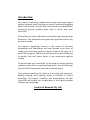
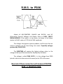
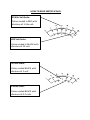
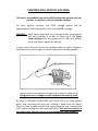
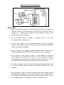
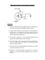
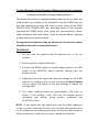
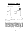
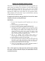
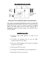
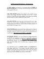
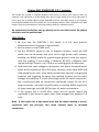
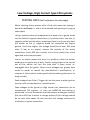
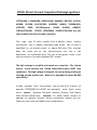
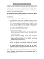
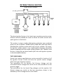
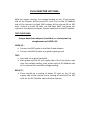
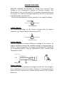
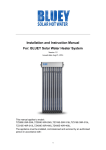
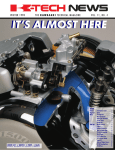
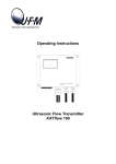
OWNERS OPERATING MANUAL Imrie®630 Motor Cycle ELECTRONIC IGNITION ANALYSER Imrie® Diagnostic Testing Australian Designed and Manufactured. Imrie® Diagnostic Testing incorporated within Small Coil Rewinds Pty.Ltd. Notes: ACKNOWLEDGEMENTS We gratefully acknowledge the valuable co‐operation and assistance given by Small Engine and Motor Cycle Manufactures and their service divisions, these include: KIORITZ CORP, JAPAN. ECHO CHAIN SAWS (AUST) HONDA AUSTRALIA PTY. LTD. STIHL CHAIN SAWS (AUST) HOMELITE TEXTRON (AUST) POULAN CHAIN SAWS (AUST) MASPORT PTY. LTD. HONDA AUSTRALIA PTY. LTD. SUZUKI AUSTRALIA PTY. LTD. YAMAHA AUSTRALIA PTY. LTD. KAWASAKI MOTORS PTY. LTD. It will be noted that a number of acknowledgements have been made to manufactures for permission to republish circuits and illustrations from their manuals. Copyright for these extracts is retained by the manufactures concerned and future reproductions by others in the whole or part is strictly prohibited. - COPYRIGHT AGREEMENT – All rights reserved – not to be reproduced in whole or in part in any form whatsoever without the written authority of: SMALL COIL REWINDS Pty. Ltd. Geelong, Australia. Web: www.imrie.com.au E‐Mail: [email protected] Introduction: Your owner’s operating manual shows how motorcycle engine ignition systems work and how to quickly locate and diagnose faults that develop. You will find conventional and complicated electronic ignition systems quite easy to check with your Imrie®630. Illustrations are clear and written instructions give step‐by‐step directions. The illustrations are generally typical and not of any particular model. The owner’s operating manual is the result of technical knowledge and information we have learned from years of studying and servicing ignition systems fitted to all types of 2 and 4 cycle engines. The simple test procedures will enable you to quickly find and repair faults in any motorcycle ignition system. To get to know your Imrie®630, try the tests on various ignition systems known to be in good working order. You will soon get the feel of the equipment and how to identify faults. Time wasted searching for faults is frustrating and expensive. Rapidly locating and repairing faults is essential in today’s workshop. The speed, simplicity and dependability of your Imrie®630 will enable you to specialise in this highly complex field of new technology. Small Coil Rewinds Pty. Ltd. TABLE OF CONTENTS Introduction What is PEAK VOLTS? An explanation ................. 1 Meter functions and Set up .............................. 2‐4 Ignition Coil Output & Testing .......................... 6‐7 Spark Plug Voltage, Testing & Diagnosis .......... 8‐10 Reserve Voltage ................................................. 11 IGNITION TYPES Battery / Points Ignition & Testing .................. 12‐13 Energy Transfer Ignition & Testing .................. 14‐15 Points Flywheel Magneto & Testing ............... 16‐17 Transistor Assisted MAGNETO & Testing ........ 18‐19 Self Energised CDI, Components & Testing ..... 20‐22 Low Voltage High Current CDI & Testing ........ 24‐25 DCCDI & Testing .............................................. 26‐27 TAI & Testing ................................................... 28‐29 Latest TAI Types .............................................. 30‐32 ENGINE MANAGEMENT TESTING Fuel Injector Testing & Scope Pattern ............ 34‐35 Engine Sensors & Description ............................ 36 WAVEFORM DISPLAYS Various Waveforms & Explanations ................ 38‐42 Using the Meter for VOLT‐DROP Testing. Starter Motor Volt‐Drop Tests ........................ 44‐45 Notes: R.M.S. to PEAK. Almost all MULTIMETERS, ANALOG and DIGITAL, read AC (Alternating Current) Voltages and display them as R.M.S. (ROOT‐
MEAN‐SQUARE). If the wave is a sine wave, as shown in the above sketch, its R.M.S. value is 0.707 of its PEAK amplitude. The voltages that Ignition systems produce, and the ones that we need to measure are far from being sine waves. Especially voltages produced by PULSE COILS. The IMRIE®630 will capture the highest voltage value, ie. the voltage at the top of the wave and be displayed by the meter. The voltage is called PEAK VOLTS, it is the voltage from ZERO (which is the line at the centre of the wave) to the TOP of the wave. Reversal of these connection will measure POSITIVE PEAK or NEGATIVE PEAK. The IMRIE®630 Meter Functions. 1 8 7
6
5
2 3 4
1. Voltage Scales. 2. Needle Zero Adjustment Screw. 3. Low Voltage Terminals. 4. Kilovolt (Kv) Probe Socket. 5. Power Switch: On/Off & Battery Test. 6. Polarity Switch, All Voltage Scales. 7. Battery Condition Indicator. 8. Voltage Selector Switch. HOW TO READ METER SCALES. 30 Kilo Volt Scale: Colour coded in RED with divisions of 1 Kilo volt. 600 Volt Scale: Colour coded in BLACK with divisions of 20 volt. 30 Volt Scale: Colour coded BLACK with divisions of 1 volt. 6 Volts Scale: Colour coded BLACK with divisions of 0.2 volts. SETTING UP AND USING THE IMRIE 630. METER ZERO‐SETTING. Before making any voltage checks, ensure that the needle points to the 0 (Zero) at the left‐hand end of the meter scale. To adjust gently turn the zero adjusting screw until the needle points to zero. TESTING THE INTERNAL BATTERIES. Switch the battery test switch to the TEST position. If the RED test lamp glows, the internal batteries are OK and the kilovolt readings will be accurate. If the RED test lamp does not glow, then the 2 (two) internal batteries are weak and must be replaced, they are located in the small draws at the rear of the meter housing. Replace and re‐test. MEASURING VOLTAGES FROM 0 THROUGH TO 600 VOLTS. 1. Be sure that the kilovolt lead jack‐plug is removed from the meter socket. 2. Be sure that the battery switch is in the OFF position. 3. Connect the RED and BLACK test leads to the RED and BLACK sockets on the front panel of the meter. 4. Turn the selector knob (0 ‐> 600 volt) to the appropriate scale to measure the voltages as are specified in the specification sheets relevant to the engine under test. 5. The specifications sheets indicate the expected voltages and polarity of the various parts of the ignition system under test. The Imrie 630 has a switch for easy reversal of polarity. When the switch is in the (+) positive position and the RED probe is measuring a voltage that voltage is (+) positive, conversely if the switch was in the (‐) negative position and the RED probe is testing a voltage, that voltage is (‐) negative. NOTE:‐ If the engine under test is not listed or has no listing, then you should start with the highest setting then work down the voltage scale. Notes: IGNITION COIL OUTPUT VOLTAGE. This test is to establish how much HIGH voltage the Ignition coil can put out, in relation to the coil primary voltage. On most ignition systems, the HIGH voltage output will be approximately 100 times greater than the PRIMARY voltage. EXAMPLE:‐ Most spark plugs with a 0.7mm gap under compression will take between 5 to 8Kv to spark, so if the Open Circuit voltage from the ignition coil is 15Kv at cranking, there is sufficient spark for starting. In most cases this test will be to establish that the spark voltage is sufficient to start the engine, and will be done at cranking speeds. The Imrie®630 can measure voltages up to 30Kv (30,000 volts). Using great care, voltages can be measured at varying rpms. By using a VARIABLE SPARK‐GAP tool (Imrie®SG1), or using special pliers, and removing the plug cap, holding it away from the Spark Plug but close enough to keep the engine running, you can read the coil’s output voltage for that particular RPM. This must be only for a very short time though and not recommended for some models!!! TESTING IGNITION COIL OUTPUT VOLTAGE. Test Procedure: 1. Remove high tension (H.T.) lead from the spark plug. 2. Clip the BLACK Kv probe GROUND clip to a good engine ground. 3. Fit the RED end of the Kv probe to the H. T. spark plug cap. 4. Ensure the other end of the Kv probe (that is the spark plug cap) is not near any metal part of the engine. 5. Plug the Kv probe plug into socket on the front panel of the tester. 6. Switch the power switch to ON. 7. Be sure the ignition switch on the machine is in the RUN or START position. 8. Crank the engine vigorously and note the meter reading on the red 30kV scale, first with the switch in the ‐30Kv position, and then in the +30Kv position. UNLESS OTHERWISE STATED the higher of the two readings will be the working voltage. A reading in the range of 15‐20Kv is considered normal. NOTE: On twin cylinder/ single ignition coil systems, two sparks are produced per revolution. One plug lead will carry a negative (‐ve) voltage while the other will be positive (+ve). 9. If the voltage is normal, then proceed with the spark plug voltage test. 10. If low or no voltage is read, then proceed with the ignition coil primary voltage test applicable to the type of ignition system being tested. BE SURE TO SWITCH POWER OFF WHEN FINISHED. SPARK PLUG VOLTAGE This test is to establish how much voltage is required by the spark plug to ignite the air/fuel mixture within the combustion chamber, under actual working conditions. A reading in the range of 5‐1OKv would be considered normal. It is difficult to nominate exact spark plug voltages required due to the variety of conditions that exist within cylinders. Experience in using your Imrie®630 will assist you in identifying these conditions. You will find that spark plugs require different voltages when used in varying engines or under varying conditions. Firing voltages are affected by some of the following conditions: 1. Compression ‐The voltage required to fire a plug will increase as compression increases. 2. Carburettor and Fuel Mixture ‐A lean mixture will require a higher voltage and a rich mixture requires a lower voltage. Too much oil in a mixture will cause the spark plug to require a higher voltage and increase the possibility of spark plug fouling. 3. Ignition Timing ‐The more advanced the ignition is set, the lower the required voltage. 4. Spark Plug Setting and Heat Range ‐the wider the plug gap, the greater the voltage required to fire the plug. The higher the heat range the lower the firing voltage. If the heat range is too high for a particular engine, the plug may cause pre‐ignition. 5. Fouled Plugs ‐When a spark plug does foul, it may be the required voltage is as high as the ignition coil output. If fouled by a carbon deposit the voltage needed may be near zero. When this happens the engine will misfire or may not start. SPARK PLUG VOLTAGE TEST. TEST PROCEDURES. 1. Remove H.T. lead from the spark plug. 2. Fit the BLACK Kilovolt GROUND clip to a good engine ground. 3. Fit the RED end of the Kilovolt probe to the H.T. spark plug cap (which you have removed from the spark plug.) 4. Fit the Kilovolt probe spark plug cap to the spark plug. 5. Plug the Kilovolt probe jack into socket on the front panel of the tester. 6. Switch the battery switch to the ON position. 7. Crank the engine, and start if required. Note the meter reading on the 30 Kv RED scale, first with the polarity switch in the Negative (‐) position, then in the Positive (+) position, UNLESS OTHERWISE STATED the higher of the two voltage readings will be the working voltage. NOTE : On multiple cylinder engines where one ignition coil supplies the voltage for the spark plugs on 2 cylinders, then one spark plug will have (‐) Negative voltage and the other will have (+) Positive voltage. The spark plug that uses (+) Positive voltage will usually have a higher voltage reading than the spark plug using (‐) Negative voltage. EXAMPLE : A spark plug with (‐) Negative voltage will usually use between (‐) 5 Kv. to 10 Kv. And the spark plug with (+) Positive voltage will usually use between (+) 10 Kv. to 15 Kv. When testing is completed, BE SURE TO TURN THE BATTERY SWITCH TO THE OFF POSITION. SPARK PLUG VOLTAGE SPARK PLUG VOLTAGE TEST POSSIBLE CAUSES Too High Too Low Intermittent Or Erratic. Cranking Idle W.O.T. Spark gap too wide, Break in H.T. lead/circuit. Spark gap too wide. Spark plug cap open circuit. One cylinder higher than others:‐ air‐leaks, lean Dribbling injector, Carburettor synchronisation . Fuel mixture too lean. One cylinder on multi cylinder engines:‐ Blocked main Jet, fouled / faulty injector, leaning out caused by blockage Cranking Low or No compression, fouled spark plug, Spark plug Gap too small, fuel mixture too rich. Idle One cylinder lower than others:‐ all of the above ! Float level too high, leaking injector, incorrect Carburettor synchronisation, and pilot jet too large or loose. W.O.T. Fuel mixture too rich. One cylinder on multi cylinder engines:‐ main jet loose Or missing sealing washer, leaking needle and seat, Stuck injector. Fuel pressure too high, dirty air filter. Spark plug. Needle loose in carburettor slide. Cracked Plug‐cap, or loose on spark plug top. Loose primary terminals on H/T coil. All Shorts / corrosion in “Earth out” type stop switches. Volt‐drop to H/T coil or bad earth on igniter. Battery charge problems. Loose engine mounts, etc, etc. IGNITION RESERVE VOLTAGE. IGNITION RESERVE VOLTAGE is the difference between the ignition coil output voltage and the sparkplug voltage. There has to be considerable ignition reserve voltage available for the ignition system to be capable of overcoming requirements under normal or heavy load conditions; for rapid acceleration and to take care of wear of both spark plug and ignition parts. Example ‐Ignition coil output of I5 Kv and spark plug using 5Kv. This leaves 10Kv of ignition reserve voltage. If there is little or no reserve voltage, then the ignition system may fail under varying load conditions when the engine is hot, but may operate normally when not loaded. Battery / Points Ignition. OPERATION:‐ 1. When the ignition switch is in the ON position and the timing cam is turned so that the breaker points are closed, the primary circuit is complete, so allowing the voltage from the battery to flow in the ignition coil primary winding. 2. As the voltage flows it creates a magnetic field in the core laminations of the ignition coil. 3. As the cam rotates to the pre‐determined point of crankshaft rotation, the breaker points are opened, thus breaking the voltage‐
flow in the primary winding. 4. At this moment, the magnetic field collapses and in doing so, it induces approximately 150 to 250 volts in the primary winding. 5. This voltage, in the primary circuit, is very important, because, depending on the characteristics of the coil, the voltage is stepped‐
up through mutual induction to between 15Kv and 25Kv (ie. 15,000 to 25,000 volts) in the secondary winding of the ignition coil. 6. This high voltage is then transmitted through the high‐tension lead to the spark plug, which ignites the air‐fuel mixture within the cylinder. 7. The condenser, which is wired in parallel with the breaker points and ground, absorbs the self‐induced voltage in the primary circuit, this prevents the voltage arcing across the opening breaker points. The voltage flow is thus bought to a quick, controlled stop. Testing Battery / Points Ignition. Ignition coil PRIMARY VOLTAGE. Test procedures:‐ 1. Set up the meter to read 0‐600 volts. 2. Connect the RED test lead to the (‐) negative side of the ignition coil and the BLACK test lead to a good engine ground. 3. If the engine will run, then start and run the engine. 4. Note the voltage on the 600 volt scale. The meter reading should be close to the voltages shown on the specification sheet. 5. If the engine won’t start, or is hard to start then crank the engine vigorously and note the voltage on the meter 0‐600 volt scale. Meter reading should be approximately 150 volts or better, if the voltage is considerably lower, then check the voltage supply to the (+) positive side of the ignition coil (Volt‐drop), breaker point resistance, breaker point gap setting, condenser and ignition switch circuit. NOTE:‐ If the engine has a high speed miss and the meter reading is erratic, consistent with the miss‐fire, this could indicate a low spring tension on the breaker points causing the points to bounce and/or loose or faulty connections in the primary circuit, caused by vibrations etc. ENERGY TRANSFER ignition. OPERATION. 1. When the flywheel rotates the magnets pass by the ignition Source coil, its flux cuts the coil windings, inducing a current. 2. As peak current occurs in the Source coil a cam opens the breaker points, they were shorting the Source coil to earth, now its path is via the High‐tension coil’s primary winding, helped by the condenser, a high voltage (140 to 160) is transferred to the Primary of the ignition coil. 3. This voltage is stepped up in the secondary windings of the ignition coil to approximately 14,000 volts (14Kv). 4. This high voltage is then transmitted through the High‐Tension lead to the spark plug, which ignites the compressed air/fuel mixture within the cylinder. 5. The condenser produces rapid transfer of the primary‐circuit current and reduces breaker‐point arcing. Testing ENERGY TRANSFER Ignition systems. ***Testing is very similar to Breaker points flywheel magneto!*** The reason the testing is required dictates what course of action you need to take, for example if the indication is of NO SPARK then the first step would be to verify that there is none, carry out an OPEN CIRCUIT HIGH TENSION COIL test, described earlier in this manual, assuming NO SPARK exists then follow the test procedure below. Other symptoms will need similar steps as outlined below, referring to data sheets for expected results. An experienced technician may go directly to the test that causes the failure otherwise use the guided steps. PROCEDURE :‐ 1. Be sure that the Ignition and Kill switches are in the run position. 2. Set the meter to read 0‐>600 volts. 3. Connect the BLACK probe to a good engine ground, the RED probe to the wire that is coming from the breaker points. Don’t disconnect it from the H.T. coil, probe into it only. 4. Vigorously crank the engine and note the voltage on the 0‐600 scale (if the reading is zero or low, change the Polarity Switch and try again), the higher of the two readings is usually the working volts. 5. The meter reading should be approximately 120 volts, or better, if the reading is low, then test the breaker point’s resistance, gap setting, spring tension, condenser and kill/stop circuits. NOTE: If the engine has high speed miss and the meter reading is erratic, consistent with the miss‐fire, this indicates low spring tension on the breaker points allowing the points to bounce and/or loose or faulty connections in the primary circuit, caused by vibrations. Mechanical breaker type flywheel magneto. OPERATION: 1. When the flywheel rotates the magnets pass by the ignition coil, its flux cuts the Primary Coil windings, inducing a current. 2. As peak current occurs in the Primary Coil a cam opens the breaker points, interrupting the current and causing the flux to collapse very quickly, inducing a high voltage (140 to 160 volts) into the Primary of the ignition coil. 3. This voltage is Stepped up in the secondary windings of the ignition coil to approximately 14,000 volts (14Kv). 4. This high voltage is then transmitted through the High‐Tension lead to the spark plug, which ignites the compressed air/fuel mixture within the cylinder. 5. The condenser produces rapid collapse of the primary‐circuit flux and reduces breaker‐point arcing. 6. Operation is the same weather the Ignition Coil is inside a flywheel, or as early British single Magnetos (Lucas, Bosch and BTH etc.). Testing Breaker Points Flywheel Magneto Ignition systems. ***Testing is very similar to Energy Transfer ignition!*** The reason the testing is required dictates what course of action you need to take, for example if the indication is of NO SPARK then the first step would be to verify that there is none, carry out an OPEN CIRCUIT HIGH TENSION COIL test, described earlier in this manual, assuming NO SPARK exists then follow the test procedure below. Other symptoms will need similar steps as outlined below, referring to data sheets for expected results. An experienced technician may go directly to the test that causes the failure otherwise use the guided steps. PROCEDURE :‐ 1. Be sure that the Ignition and Kill switches are in the run position. 2. Set the meter to read 0‐>600 volts. 3. Connect the BLACK probe to a good engine ground, the RED probe to the KILL/STOP switch terminal coming from the breaker points. 4. Vigorously crank the engine and note the voltage on the 0‐600 scale (if the reading is zero or low, change the Polarity Switch and try again), the higher of the two readings is usually the working volts. 5. The meter reading should be approximately 120 volts, or better, if the reading is low, then test the breaker point’s resistance, gap setting, spring tension, condenser and KILL/STOP circuits. NOTE: If the engine has high speed miss and the meter reading is erratic, consistent with the miss‐fire, this indicates low spring tension on the breaker points allowing the points to bounce and/or loose or faulty connections in the primary circuit, caused by vibrations. Transistor Assisted MAGNETO. IGNITION
STOP
CIRCUIT
HT COIL
Very SPECIAL
PRIMARY WINDING
ISOLATED from SECONDARY.
SOURCE #2
TRANSISTOR
SWITCH
SOURCE #1
THYRISTOR
SWITCH
ADVANCE
/
RETARD
CIRCUIT
PULSA
A very common ignition fitted to Stationary engines notably Kawasaki KF150 & 200s, the above drawing represents one of only two motorcycles that I have found that use it, an early ‘80s DR250‐S, the other being another Suzuki, a TC100. Operation is the same as Energy Transfer systems, current produced by the Source coil/coils is shorted to earth by the TRANSISTOR SWITCH (same as a set of points would) the THYRISTOR SWITCH (acts as the opening CAM) opens the TRANSISTOR SWITCH causing current to be Transferred into the H.T. coil’s primary winding thus causing a high voltage to be induced into the secondary winding. Timing is controlled by a Pulse/trigger coil and electronics. Testing T.A.I. Magneto Ignition systems. The reason the testing is required dictates what course of action you need to take, for example if the indication is of NO SPARK then the first step would be to verify that there is none, carry out an OPEN CIRCUIT HIGH TENSION COIL test, described earlier in this manual, assuming NO SPARK exists then follow the test procedure below. Other symptoms will need similar steps as outlined below, referring to data sheets for expected results. An experienced technician may go directly to the test that causes the failure otherwise use the guided steps. PROCEDURE : 1. Be sure that the Ignition and Kill switches are in the run position. 2. Set the meter to the 0‐600 volt range. 3. Connect the BLACK probe to a good engine ground. 4. Disconnect the Ignition Stop/Kill wire at the igniter, insert the RED probe into it, vigorously crank the engine and note the reading on the meter (if the reading is zero or low, change the Polarity switch and try again), the higher of the two readings is usually the working volts. A reading of 120 volts or more would be considered normal. 5. Low or no voltage could indicate faulty Source or Pulse/Trigger coils. Disconnect the Igniter from the engine. 6. Set the meter to read the 0‐30 volt range. 7. With the BLACK probe to ground, place the RED probe into the Source coil’s open connection. Crank the engine and note the reading, good output would be 20 volts or greater. 8. Set the meter to read the 0‐6 volt range. 9. Check the Pulse/Trigger coil as above. Readings between 2 to 4 volts would be considered to be normal. Note : If the engine has a high speed miss and the meter readings are erratic, consistent with the miss‐fire, this could indicate loose or corroded connections. SELF ENERGISED CDI SYSTEM. C1
D1
EXCITER
COIL
High Volts
Low Amps
PULSA
COIL
Small
Spikes
T1
ADVANCE
RETARD
CIRCUIT
SECONDARY COIL
0.2 to 1 ohm
Primary
CDI systems can be simplified roughly as illustrated above. High voltage is generated by the EXCITER coil, rectified by the diode (D1) and stored on the CAPACITOR (C1). (T1) SWITCH is turned ON by the PULSE COIL, (timing, advance / retard is controlled by the TIMING CIRCUIT). The HIGH voltage, (100 to 300 volts) stored on (C1) is DISCHARGED through the Primary winding of the IGNITION COIL, a SPARK is produced. COMMON TO ALL TYPES. 1. All have a high voltage generator to charge up the CAPACITOR. 2. The ignition coil (secondary coil) has very low OHMS resistance, between 0.2 and 1 OHM. 3. Some form of PULSE (trigger) coil, this may‐be the negative swing of the main EXCITER. 4. Earth‐out type STOP / KILL switch. 5. The voltage at the SECONDARY COIL is always NEGATIVE!!!!! 6. Spark energy increases as revs increase. Self Energised CDI System:‐ Components. The HIGH voltage is generated by a Permanent Magnet FLYWHEEL or ROTOR and STATOR assy. This may consist of either or both HIGH and LOW speed EXCITER coils. LOW SPEED EXCITERS produce high voltage at low speeds, as revs increase this voltage diminishes. Resistance of this coil is usually between 100 and 500 ohms, output voltage is predictable ie. at cranking speeds, between 90 and 150 PEAK VOLTS (open circuit). HIGH SPEED EXCITERS start at low volts and increase with revs. In some systems this coil also sends a TRIGGER pulse. Resistance of this coil is usually between 5 and 50 ohms, output is LOW at cranking, between 10 and 30 PEAK VOLTS (open circuit). PULSE (TRIGGER) coils can be internal type (underneath the Flywheel) or external type (outside flywheel or even removed from area, ie. on camshaft or under the clutch cover). Resistances vary considerably from 5 to 500 ohms. ONCE AGAIN the VOLTAGES are SIMILAR!!! COIL PRIMARY VOLTAGE. As a rule of thumb the voltage measured at the EXCITER coils should be, or nearly be, the same value coming out and going to the IGNITION coil. THIS IS A NEGATIVE VOLTAGE!!!! MEASURED BY PLACING THE BLACK PROBE TO THE PRIMARY INPUT WIRE. THE RED PROBE GOES TO EARTH (this is measured CLOSED CIRCUITED). Almost ALL CDI ignitions are STOPPED / KILLED by EARTHING OUT a high voltage output wire. The voltage at the KILL WIRES are high enough to break down poor insulation and will ARC across corrosion in switches. This high voltage also increases as revs increase, therefore what maybe OK at LOW RPM may not be at HIGH RPM. Testing SELF ENERGISED C.D.I. systems. The reason the testing is required dictates what course of action you need to take, for example if the indication is of NO SPARK then the first step would be to verify that there is none, carry out an OPEN CIRCUIT HIGH TENSION COIL test, described earlier in this manual, assuming NO SPARK exists then follow the test procedure below. Other symptoms will need similar steps as outlined below, referring to data sheets for expected results. An experienced technician may go directly to the test that causes the failure otherwise use the guided steps. PROCEDURE :‐ 1. Be sure that the IGNITION / KILL switch is in the start position (disconnection at the igniter is a good idea). 2. Set the meter to read 0‐600 volts. 3. Set the POLARITY switch to the (‐) Negative position. Insert the RED probe into the connector that joins to the high tension coil’s primary winding, the BLACK probe to a good engine ground, crank the engine, note the reading, if the reading is between 90‐150 (‐) Negative volts replace the High Tension coil, if low or no reading go to the next step. 4. Now check the input voltages to the igniter, this where the specification sheet will be needed as there are many varieties, some have HIGH and LOW speed exciter coils, some have one that does two jobs, charging the capacitor and triggering the spark. One method to check that the input voltages are adequate is to test the voltage at the Kill switch connection, this is performed with all connections connected, except for the kill / stop connection, into which the RED probe is inserted, BLACK to ground, all types have high volts (90‐150) at their kill switch connections. 5. If the system has a PULSE COIL, these tell the igniter where the crankshaft is and when to spark, their Peak voltages vary between 2‐9 volts. Note : If the engine has a high speed miss and the meter reading is erratic, consistent with the miss‐fire, this could indicate loose or corroded connections. Low Voltage, High Current type CDI systems Late CR500, CR125 & 250 from ’90, CRF’s, RM’s KX’s, KTM’s and Husqvarna’s (with Japanese ignitions), some Polaris 4‐
wheelers and Yamaha Banshee (YFZ) are just some models that are fitted with this type. I don’t know what the correct name for this type of ignition is, I refer to it as CHOPPER TYPE. It is becoming popular because it is cheaper to manufacture because the exciter coils are wound with much heavier wire and many less turns than the earlier Self Energised CDI systems. HOW THE HIGH VOLTAGE IS GENERATED At cranking and low RPMs the output from the exciter is too low (30‐
40 volts) to charge the capacitor for adequate spark energy. Electronics in the igniter amplify the voltage, much like a points magneto system does, as the magnetic flux cuts the windings a switching transistor holds the output low, when the current is at its maximum the transistor is turned off (opens), this creates a rapid increase in voltage in the exciter / capacitor circuit (150 plus volts is normal), this high voltage then charges the capacitor to a high enough potential to produce good spark, as the revs increase the output from the exciter coil increases, in most cases the CHOPPER system is by‐passed as the exciter puts out enough voltage at the higher revs. Other components in the system, Pulse/Trigger coil, flywheel & high tension coil are the same as a conventional Self Energised CDI system. Continued........ Low Voltage, High Current type CDI systems Continued ..... TESTING HELP (with reference to next page) When checking these systems with a Peak Volt meter the testing is best done In‐Circuit i.e. with it all connected and sparking or trying to make spark. Using a special probes (a straightened out paper clip is good) probe into the Exciter to Igniter connections, (+) positive probe into one, (‐) negative probe into the other, sometimes there is only one wire from the exciter so the (‐) negative would be connected the Engine ground. Crank the engine, the voltage should be at least 150 peak volts. If low or no output, reverse the polarity of the probe connections (Imrie 630 has a switch on the front panel) then crank again and check the peak volts. Low or no output means that there is a problem, either the exciter winding or the igniter are at fault. Further testing then can be carried out on the exciter coil, but this time with it Open circuit i.e. unplugged from the igniter. Open circuit voltages vary greatly from model to model so consult the manufacturer’s specifications, or compare it with another known good value (another good reason to keep records). Peak voltages from Pulse / Trigger coil are the same as other ignition types or refer to manufacturer’s specifications. Peak voltages at the Igniter to High tension coil connection are as conventional CDI systems, i.e. they are NEGATIVE and testing is performed in circuit. Remember that the positive probe goes to earth (the Imrie 630 has a switch to change polarity!!) this voltage should be no more than about 15 volts less than the voltage measured at the Exciter to Igniter connection. Testing LOW volts HIGH current C.D.I. systems. ***Testing is very similar to Self Energised CDI!*** The reason the testing is required dictates what course of action you need to take, for example if the indication is of NO SPARK then the first step would be to verify that there is none, carry out an OPEN CIRCUIT HIGH TENSION COIL test, described earlier in this manual, assuming NO SPARK exists then follow the test procedure below. Other symptoms will need similar steps as outlined below, referring to data sheets for expected results. An experienced technician may go directly to the test that causes the failure otherwise use the guided steps. PROCEDURE :‐ 1. Be sure that the IGNITION/KILL switch is in the start position (disconnection at the igniter is a good idea). 2. Set the meter to read the 0‐600 volt range. 3. Set the POLARITY switch to the (‐) Negative position. Insert the RED probe into the connector that joins to the high tension coil’s primary winding, the BLACK probe to a good engine ground, crank the engine, note the reading, if the reading is between 130‐150 (‐) Negative volts replace the High Tension coil, if low or no reading go to the next step. 4. With the BLACK probe to ground, insert the RED probe into the disconnected Kill/Stop connection. Change the Polarity switch to read (+) Positive voltages, then crank the engine, a reading of 130 volts or greater would be considered normal. 5. Set the meter to read the 0‐30 volt range. 6. Now check the input voltages to the igniter. This type usually have a two (2) wire, above ground type exciter coil, insert the BLACK and RED probes one into each, crank the engine, 20‐30 volts would be normal. 7. Check for SHORTS to GROUND by placing the BLACK probe on ground, there must NOT be any voltage from either exciter connection while cranking the engine! 8. Set the meter to read the 0‐6 volt range. 9. The PULSE COIL test is as above, a normal reading would be 2‐4 volts. Note : If the engine has a high speed miss and the meter reading is erratic, consistent with the miss‐fire, this could indicate loose or corroded connections. DCCDI (Direct Current Capacitor Discharge Ignition) LTF250/300, LTA400/500, DRZ250/400, RMX250, RGV250, KLF220, KLF400, KVF360, KLX250/300, KDX250E, NX650, TRX300/450, VTR1000, RC30, XL250(Degree), XR650, XLV600, NSR250, TTR230/250/600, TZ250E, YZF600(R6), YFM250/350/400 are just some models that use this type of ignition. This type uses 12 volts, usually from a battery. Some enduro motorcycles use a Battery Eliminator type circuit. The 12 volts is amplified by an inverter circuit to about 200 volts. (The inverter does the same job as the exciter/source coil, but is not dependent on crankshaft rpm). The rest of the igniter circuit is the same or similar to the self‐energised CDI system. The high voltage is rectified and stored on a capacitor. The timing control circuit switches the Silicon controlled rectifier (SCR) into conduction. The high voltage is dumped into the primary winding of the high tension ignition coil. Where it is amplified to about 60,000 volts (60kV). In their simplest form they require four or five (4 or 5) wires to operate, LTF250/300 & KLF400 are examples, most have many more. Inputs:‐ Rotation Direction, Neutral, Reverse, Side Stand, Gear Position sensors etc. Outputs:‐ to allow starter motors to operate, to operate Exhaust servos, carburettor power‐ jets etc. These are just a few, and add to their complication. Testing Direct Current DCCDI systems. The reason the testing is required dictates what course of action you need to take, for example if the indication is of NO SPARK then the first step would be to verify that there is none, carry out an OPEN CIRCUIT HIGH TENSION COIL test, described earlier in this manual, assuming NO SPARK exists then follow the test procedure below. Other symptoms will need similar steps as outlined below, referring to data sheets for expected results. An experienced technician may go directly to the test that causes the failure otherwise use the guided steps. PROCEDURE :‐ 1. Set the meter to read the 0‐600 volt range. 2. Set the POLARITY switch to the (‐) Negative position. Insert the RED probe into the connector that joins to the high tension coil’s primary winding, the BLACK probe to a good engine ground, crank the engine, note the reading, if the reading is between 90‐150 (‐) Negative volts replace the High Tension coil, if low or no reading go to the next step. 3. Set the meter to read the 0‐30 volt range. 4. Check Igniter power supply. • Where there is a Battery fitted to the vehicle, locate the Igniters DC power connection, check for good supply while cranking the engine. • Some motorcycles (enduro mainly) have a Battery Eliminator type DC supply. These need to be cranked to produce the required POWER, 9 to 10 volts at cranking speeds would be considered OK. 5. Most late models have safety lock‐out sensors which may prevent the ignition from sparking. Consult the individual models wiring diagram for their location and operation. 6. All systems have Pulse/Trigger coils, these tell the igniter where the crankshaft is and when to spark. A Peak voltage of 2 to 4 volts would be considered good. Note : If the engine has a high speed miss and the meter reading is erratic, consistent with the miss‐fire, this could indicate loose or corroded connections. TAI or TRANSISTOR ASSISTED IGNITION. Basically TAI is a Solid State SET OF POINTS. The Switching Transistor acts as the POINTS, i.e. when closed, current flows through the PRIMARY winding to earth. Upon OPENING the current stops causing a RAPID COLLAPSE of the magnetic field, this INDUCES a very large voltage in the SECONDARY winding i.e. spark. The TIMING of the spark is usually controlled electronically but can be by Bob‐weights. Secondary Coil PRIMARY resistance is usually between 2.2 and 3.3 ohms. The reason for this is to allow MAXIMUM current build‐up between sparks. Some manufactures go even LOWER, 1 ohm or less, using Current limiting transistors or Ballast resistors, so consult the makers specifications when replacing coils. In almost every Japanese TAI system, a short time after the ignition switch is turned ON and there is no CRANKING pulses the MAIN drive transistor OPENS, this is to prevent any damage that may be caused by the high current drawn by these LOW ohm coils, 3 ohms at 12 volts equals 4 amps., this will not only flatten batteries but would destroy coils and transistors. HIGH CURRENT is also switched by the Ignition and the EMERGENCY CUT‐OUT switches. Poor contacts will cause VOLT DROP and lower the output. The IGNITER units will operate down to 6‐7 volts, but they don’t like 15 plus volts, this increase the CURRENT in the TRANSISTOR and may damage the ELECTRONICS. After REPLACING an IGNITER or High tension coil, BATTERY CHARGE RATE must be checked.! If suspect, replace the REGULATOR. Testing T.A.I. Ignition systems. The reason the testing is required dictates what course of action you need to take, for example if the indication is of NO SPARK then the first step would be to verify that there is none, carry out an OPEN CIRCUIT HIGH TENSION COIL test, described earlier in this manual, assuming NO SPARK exists then follow the test procedure below. Other symptoms will need similar steps as outlined below, referring to data sheets for expected results. An experienced technician may go directly to the test that causes the failure otherwise use the guided steps. PROCEDURE :‐ 1. Set the meter to read 0‐30 volts. 2. Place the BLACK probe on a good engine / frame ground. 3. Using the RED probe check the battery voltage, must be 12 volts or better, (if no reading check that the polarity switch is in the (+) Positive position), if a lower than 12 volt reading is indicated either replace or charge the battery. 4. Turn the ignition switch to the ON position, noting again the battery voltage, if the motorcycle has Lights‐On there should only be a slight drop in the reading, while cranking the engine the battery voltage will drop but this should not be more than about 1 to 2 volts. 5. With the ignition ON and NOT cranking check the voltage at both the (+) positive and (‐) negative terminals if the high tension coil/s, battery voltage should be present on both. 6. Set the meter to read 0‐600 volts, while cranking the (‐) negative H/T coil voltage should be approx. 140‐180 volts, while the (+) positive should be battery voltage. If OK replace the H/T coil and test again for spark. 7. Set the meter to read 0‐6 volts. 8. Using both probes (one on to each connector) check the OPEN circuit voltage of the Pulse/trigger coil/coils, at cranking speeds, usually between 2‐4 volts is OK. Refer to specification charts for other readings. 9. With reference to the model under test’s wiring diagram check any Safety Lock‐out sensors, eg. Side stand, neutral, reverse, tip‐over or Rotation Direction sensors for correct operation. 10. Replace the igniter, or best, try the igniter on a known good running motorcycle. Note : If the engine has a high speed miss and the meter reading is erratic, consistent with the miss‐fire, this could indicate loose or corroded connections. Wasted Spark TAI System. Distributorless Ignition component layout. Twin Lead High Tension Coil Construction. TESTING DISTRIBUTORLESS IGNITION. ‐Wasted Spark System – NOTE: Consult the vehicle manufacturers service manual for location of all the Ignition Control Circuits and also the specific sensor voltages within this type of ignition system. Test procedures for the ignition coil primary voltage and the crankshaft sensor voltages are similar to the test procedures on the previous page. The test procedures for the spark plug voltages and the ignition coil output voltage are similar to the test procedures shown in the secondary circuit voltage section of this book, but the only difference being that the Wasted Spark ignition coil has two High Tension leads, one having (‐) Negative voltage and the other having (+) Positive voltage. When reading the two spark plug voltages on the one ignition coil, one spark plug will have a slightly higher or lower voltage reading than the other spark plug of the opposite polarity. When performing the ignition coil output voltage test as shown in the Secondary Circuit Voltage section, you should check the voltage from both High Tension leads, they should be the same, as the other end of the secondary windings goes to ground via, the other spark plug fitted to the engine. There could be short to ground within the High Tension lead / coil, this could be the cause of a misfire or no spark on one cylinder. NOTE: Motoplat and Femsatronic Twin lead High Tension coils have a CENTRE‐TAP which means that each lead will have resistance and therefore voltage to ground. DISTRIBUTORLESS IGNITION. ‐One Coil per Cylinder ‐ The above Ignition System is the latest type now being used on motor vehicles and will probably be used on almost all motor vehicles with spark ignition in the future. This system is using a similar philosophy as the first mass produced motor car, the 4 cylinder T.Model Ford of 1908‐1927 which also had a Distributorless Ignition system with one coil per cylinder. Of course, the Ignition system above is very sophisticated computer controlled system compared with the simple system fitted to the T.Model, none the less, it looks like we have turned a full circle with Ignition systems in the automobile industry. TEST PROCEDURES: Consult the vehicle manufacturers service manual for location of all the Ignition Control Circuits and also the specific sensor voltages within this type of Ignition system. Test procedures for the Ignition Coil Primary Voltage and the crank‐shaft sensor voltages are similar to the test procedures on the previous pages. Test procedures for the Spark Plug voltages and the Ignition Coil Output voltage are similar to the test procedures shown In the Secondary Circuit Voltage section of this book. Notes: FUEL INJECTOR VOLTAGE. With the engine running, the voltage reading on the 12 volt supply side of the Injector will be around 15 volts, but on the EFI Module side of the Injector the Back EMF voltage will be around 80 to 100 volts. If there is under 50 volts, the low Back EMF may cause the system to shut down and log an Injector code fault In the EFI Module. TEST PROCEDURE: Using a Back Probe adaptor if available, or a handy tool is a straightened‐out PAPER CLIP. HOOK UP : • Connect the RED probe to the Back Probe adaptor. • Connect the BLACK probe to a good engine ground. TEST: • Start and run engine If possible. • Back probe into the 12 volt supply side of the Fuel Injector and note the voltage reading, then probe into the EFI Module side of the Injector and note the voltage reading. RESULTS : • There should be a reading of about 15 volts on the 12 volt supply side of the Injector and a reading of around 80 to 100 volts on the EFI Module side of the fuel Injector. FUEL INJECTOR. Typical E.F.I. Fuel Injector, shown are expected voltages. Oscilloscope waveform display of the back EMF voltage on the Fuel Injector terminal going to the EFI module. ENGINE SENSORS. RESISTIVE SENSORS are designed to change their resistance and voltage as the Temperature, Position or Pressure changes. This Information is then used by the ECU to optimize the performance of the engine. The reference voltage supplied by the ECU to the sensor could be between 5 and 9 volts. ‐Consult the manufacturers service manual for the specific voltages ‐ 1‐WIRE SENSOR. The Resistance/Voltage of the Sensor changes with the engine condition. eg. Engine Coolant Temperature (ECT). 2‐WIRE SENSOR. The ECU supplies a constant Reference Voltage to the Sensor, as engine conditions change the modified voltage is returned back to the ECU. Typical sensors are: Air Charge Temperature (ACT), Manifold Air Temperature (MAT), Vane Air Temperature (VAT), Throttle Body Temperature (TBT). 3‐WIRE SENSOR. The Sensor receives a Reference Voltage from the ECU, the voltage Is then modified by the sensor (either Position or Pressure) and sent back to the ECU. Sensors are: Throttle position sensor (TPS) Tip‐Over sensor etc. Notes: WAVEFORM DISPLAYS. Fig. 1. ANALOGUE SIGNAL. An analogue signal is usually generated by a pulse coil & magnet and will have a positive pulse and a negative pulse of about the same voltage for each polarity. Other analogue signals may have a strong pulse on one polarity and little or no voltage on the other pulse. In most cases the higher voltage reading would normally be considered the working voltage and polarity of the signal under test. It should also be noted that the analogue pulse voltages will increase as the engine speed increases and decrease as the engine speed decreases. Fig.2. DIGITAL/SQUARE WAVE SIGNAL. The signals from the HALL or OPTICAL sensor in the distributor or from the crankshaft sensors going to the ignition Module and/or to the ECU Module are of a digital square wave form and will usually be between 5 and 9 volts. They will normally have a constant voltage throughout the entire RPM range of the engine. Fig. 3. FUEL INJECTOR SIGNAL. With the engine running, the Voltage reading on the ECU side of the Fuel Injector will normally be about 80 volts, this is the Back EMF voltage or Self Induced voltage which occurs within the Injector. This Back EMF voltage is monitored by the ECU to detect Fuel Injector faults. Fig. 4. IGNITION COIL PRIMARY VOLTAGE. On the (‐) Negative terminal of the Ignition coil, which goes to the Breaker Points or the Electronic Ignition Module, will have a voltage reading from around 150 to about 250 volts when cranking the engine over or while it is operating. This is the Back EMF voltage or Self Induced voltage which occurs within the ignition coil. This Back EMF voltage is monitored by the ECU to detect ignition faults. WAVEFORM DISPLAYS. FIG. 1 Analogue signal. FIG. 2 Digital Signal. FIG. 3 Fuel Injector Signal. FIG. 4 Ignition Coil Primary (‐) Signal. Ignition High Tension coil Oscilloscope traces. FIG. 1 Spark plug firing voltage. FIG, 2 Primary voltage. Pulse / Trigger coil, TRACE example. HALL EFFECT / OPTICAL Sensor, Trace example. Notes: Using the “METER” to check for VOLT‐DROP Starter motor circuit. VOLTAGE DROP is the drop in voltage due to resistance between two points in an electrical circuit. In a perfect system, all the above tests (except for #1), with the starter motor CRANKING the engine, would read (0) ZERO volts. NOTE : Before testing make sure that all connections are clean & tight, check cables for frayed or damaged insulation or corrosion. Refer to Table opposite for suggested results. DON’T FORGET that the EARTH cable can also be a problem !! All circuits, Ignition, Battery charging, Lighting, Instruments and Safety circuits can be checked in a similar manner. Starter Motor – VOLT‐DROP test chart. Approximate Meter Readings
With Starter Button If it Reads. Pressed. 1. * 12 volts *10‐>11 volts Below 10 volts Still at 12 volts 2. * 12 volts 0 ‐> 1 Over 1 volt 3. 0 volts 0.5‐>1 volt Over 1 volt 4. 0 volts 0.5‐>1 volt Over 1 volt 5. 0 volts 0.5‐>1 volt Over 1 volt 6. * 12 volts 0.5‐>1 volt Over 1 volt 7. * 12 volts 0.5‐>1 volt Over 1 volt 8. 0 volt 0 volt Above 0 volts 9. 0 Amps See Note Below. Step# ** As Hooked Up. Cause. Weak Battery. Open Circuit. Loose terminals. Open Circuit. High resistance. Loose terminal or broken wire. Loose terminals. Loose or corroded terminals. Defective solenoid. Loose terminal. Poor ground, loose bolts. Starter Motor. NOTE: In step # 9 check the manufacturers current draw specifications for each motor being tested. Use a “Clamp” type Ammeter over the battery to solenoid high current cable. * Meter set on 0 ‐> 30 volts. All other readings are set on 0 ‐> 6 volts ** Voltage readings are taken before starter button is pressed.