1
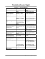
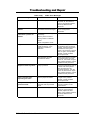
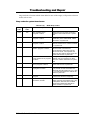
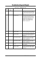
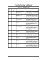
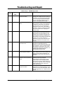
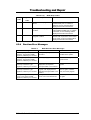
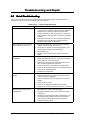
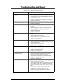
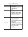
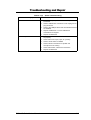
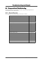
6
Chapter
Troubleshooting and Repair
6.1
Introduction
This chapter provides the most common problem encountered with the A440 notebook
computer and some troubleshooting means. Some of the common problems are:
•
•
•
•
•
•
•
•
6.1.1
System BIOS Related Problems
LCD Display Problems
System Power and Boot-Up Problems
External Interface Problems (Serial, Printer, CRT, IR, USB, PS/2)
Audio Problems
PCMCIA Problems
Power Management Problems
Input Device Problems (Keyboard and Glidepad)
Helpful Starters
Here are a few helpful starters to begin with before troubleshooting the notebook:
•
Is there any external power source connected to the computer?
•
Does the battery installed been fully charged?
•
Is the computer turn on and the POWER LED activated?
•
Are all cables connected properly and securely?
•
Are all needed device drivers been installed properly?
•
Have you checked your AUTOEXEC.BAT and CONFIG.SYS files for errors?
•
Is the Power Management function enabled under BIOS Setup? Press any key to
wake system up again.
6.2
System BIOS Related Problems
This section provides you with information on how the BIOS handles errors encountered
during POST (Power On Self Test) and translate them to beep codes and error messages.
Refer to this whenever you encounter error messages or beep codes generated by the
computer during startup.
6.2.1
POST Messages
The following is a summary of the Phoenix BIOS startup error messages that is displayed
on the notebook’s screen. These messages help you in understanding some of the
notebook’s problems that may be corrected by entering the BIOS SETUP program and
checking the original values.
FIC A440 Series Service Manual
6-1
Troubleshooting and Repair
Table 6-1(a)
Message
Diskette drive A failure
POST Error Messages
Possible Cause
Action
The drive failed or is missing.
Check the drive to determine the
problem.
Floppy Disk Controller is
disabled.
Enabled the FDD Controller.
Diskette read failure - press
F1 to retry boot, F2 for
SETUP utility
The diskette is either not
formatted or is defective.
Replace the diskette with a
bootable diskette and retry.
Display adapter failed,
using alternate
The primary video adapter
failed.
Check the primary video
adapter.
Gate A20 failure
The keyboard controller is not
accepting command,
specifically, the enable and
disable A20 command.
Check the keyboard controller
and system board. Turn the
power off, then back on again. If
the problem persists contact
qualified service personnel.
Fixed disk configuration
error
The specified configuration is
not supported or doesn't
match the actual hardware
installed.
Correct the fixed disk
configuration.
Fixed disk controller failure
The fixed disk may be
defective.
Try rebooting. If that doesn't
work, replace the fixed disk.
Fixed disk read failurepress F1 to retry boot, F2
for SETUP utility
The fixed disk may be
configured incorrectly or is
defective.
Check the drive type selected in
SETUP. Try rebooting. If that
does not work, replace the fixed
disk.
Pointer device failure
The PS/2-style mouse failed.
Try rebooting. If problem
persists, check the mouse, it's
cable and connector.
No boot device available press F1 to retry boot, F2
for SETUP utility
Either diskette drive A:, the
fixed disk, or both the
diskette and fixed disk are
defective.
Try rebooting. If problem
persists, replace the diskette or
the fixed disk.
No boot sector on fixed
disk – press F1 to retry
boot, F2 for SETUP utility
The C: drive is not formatted
or is not bootable.
Format the C: drive and make it
bootable.
Not a boot diskette - press
F1 to retry boot, F2 for
SETUP utility
The diskette in drive A: is not
formatted as a bootable
diskette.
Replace the diskette with a
bootable diskette and try
rebooting.
No timer tick interrupt
The timer chip has failed.
Check the system board, Turn
the power off, then back on
again. If the problem persists,
contact qualified service
personnel.
Shutdown failure
Either the keyboard controller
is not accepting the reset
command or the associated
reset logic has failed.
Check the keyboard controller
and system board. Turn the
power off, then back on again. If
the problem persists, contact
qualified service personnel.
Time of day not set - run
SETUP program
Real Time Clock not set.
Run SETUP utility.
6-2
FIC A440 Series Service Manual
Troubleshooting and Repair
Table 6-1(b)
Message
POST Error Messages
Possible Cause
Action
Timer 2 failure
The timer chip has failed.
Check the system board. Turn
the power off, then back on
again. If the problem persists,
contact qualified service
personnel.
F2 to enter ROM-based
SETUP
Invalid configuration
information must be changed.
You must run SETUP utility and
correct configuration
information.
Invalid configuration
information - please run
SETUP
Display adapter is configured
incorrectly.
Run the SETUP utility.
Memory size is incorrect.
Wrong number of diskette
drives.
Other configuration errors.
Keyboard clock line failure
The keyboard, the keyboard
cable connection, or the
keyboard controller is
defective.
Make sure the keyboard cable
and keyboard are connected
properly. Check the keyboard
controller and the system
board. Turn the power off, then
back on again. If the problem
persists, contact qualified
service personnel.
Keyboard data line failure
The keyboard controller
firmware has failed.
Check the keyboard controller
and system board. Turn the
power off, then back on again.
If the problem persists, contact
qualified service personnel.
Keyboard stuck key failure
A key is jammed.
Locate the jammed key and fix
it. Make sure the keyboard
cable and keyboard are
connected properly. Turn the
power off, then back on again.
If the problem persists, contact
qualified service personnel.
Memory failure at hexvalue, read hex-value,
expecting hex-value
Circuitry associated with the
memory chips has failed.
Turn the power off, then back
on again. If the problem
persists, contact qualified
service personnel.
Unexpected interrupt in
protected mode
Hardware interrupt or NMI
occurred while in protected
mode.
Check the timer chip or the
interrupt controller on the
system board.
Real time clock failure
The RTC or battery failed.
Run SETUP and turn the power
off and on. If the problem
persists, replace the RTC
battery. If the problem remains,
contact qualified service
personnel.
FIC A440 Series Service Manual
6-3
Troubleshooting and Repair
6.2.2
Informational Messages
This section lists the messages that provide information to the user but require no action.
Table 6-2
Message
BIOS Informational Messages
Meaning
nnnK Base Memory
The amount of base memory that tested successfully.
nnnK Extended
The amount of extended memory that tested successfully.
Memory tests terminated by
keystroke
The message indicates that a user pressed the spacebar
while memory tests were running and stopped the
memory tests.
Press the F1 key to continue
This message indicates that an error was found during
POST. Pressing the F1 key allows the system to attempt
to reboot.
Beginning memory test Press the
SPACEBAR to terminate the
memory test
A user can stop the memory tests by pressing the
spacebar.
Press the F1 key to continue, F2
to run the Setup utility
This message indicates that an error was found during
POST. Pressing the F1 key allows the system to attempt
to boot. Press F2 allows users to run the ROM-based
SETUP utility to correct configuration information.
6.2.3
Beep Codes
Beep codes are used to identify a POST error that occurs when the screen is not available.
Once the screen is operating, diagnostic messages are reported to the screen. There are beep
codes for both fatal and non-fatal system board errors.
No beep code is generated if a test is aborted while in progress. However,
diagnostic cards can be installed in order to display the contents of the
diagnostic port 80h and identify the area of failure.
Explanation of test terms for beep code table
The following terms are used in the Test Performed column of the beep code table:
1. Pattern test - One or more particular patterns are written to a location then read back
from the same location. Examples of patterns used are 55h and AAh. If the value read
does not match the value written, the test is considered a failure.
2. Rolling ones test - Several patterns are constructed. These patterns represent a one rolling
through the given location. For example, to roll a one through three bits, the following
patterns would be constructed: 001, 010, 011, 100, 101, 110, and 111. The patterns are
written to the location and then read back, one by one. If the value read does not match
the value written, the test is considered a failure.
3. Rolling zeros test - Several patterns are constructed. These patterns represent a zero
rolling through the given location. For example, to roll a zero through three bits, the
following patterns would be constructed: 011, 001, and 000. The patterns are written to
the location and then read back, one by one. If the value read does not match the value
written, the test is considered a failure.
4. Checksum test - All of the values in a given range of locations are added together. The
6-4
FIC A440 Series Service Manual
Troubleshooting and Repair
range includes a location which when added to sum of the ranges, will produce a known
result, such as zero.
Beep codes for system board errors
Table 6-3 (a)
BIOS Beep Codes
Beep
Code
Diagnostic
Description
Test Performed
none
01h
CPU registers test in
progress or failure
Pattern test of most of the 16-bit CPU
registers. Failure will result in a system
halt.
1-1-3
02h
CMOS write/read test in
progress or failure.
Rolling ones test in the shutdown byte
(offset 0Eh) of the CMOS RAM. Failure
will result in a system halt.
1-1-4
03h
ROM BIOS checksum test in
progress or failure.
The range of ROM that includes the
BIOS is checksummed. Failure will result
in a system halt.
1-2-1
04h
Programmable interval timer
0 test in progress or failure.
Over a period of time, the current count
values in timer 0 are read and
accumulated by ORing them into the
values read so far. It is expected that
during the time period, all bits will be set.
Failure will result in a system halt.
1-2-2
05h
DMA channel 0 address and
count register test in progress
or failure.
Rolling ones and rolling zeros test of the
address and count registers of DMA
channel 0. Failure will result in a system
halt.
1-2-3
06h
DMA page register write/read
test in progress of failure.
Pattern test of DMA page registers.
Failure will result in a system halt.
1-3-1
08h
RAM refresh verification test
in progress or failure.
Over a period of time, the refresh bit (bit
4) in port 60h is read and tested. The
refresh bit should toggle from 0 to 1, then
1 to 0 within the time period. Failure will
result in system halt.
none
09h
First 64K RAM test in
progress.
No specific test is performed - just
indicates that the test is beginning.
1-3-3
0Ah
First 64K RAM chip or data
line failure, multi-bit.
The first 64K of RAM is tested with a
rolling ones test and a pattern test. If any
of the pattern tests fail, then the BIOS
reports that multiple data bits failure.
Failure results in a system halt.
Code
FIC A440 Series Service Manual
6-5
Troubleshooting and Repair
Table 6-3 (b)
BIOS Beep Codes
Beep
Code
Diagnostic
Description
Test Performed
1-4-2
0Dh
Parity failure first 64K RAM
At the completion of the rolling ones and
pattern tests of the first 64K, the BIOS
checks the parity error bits (bits 7 and 6)
of port 60h. Failure results in a system
halt.
2-1-1
10h-1Fh
First 64K RAM chip or data
line failure on bit x
The first 64K of RAM is tested with a
rolling ones test and a pattern test. If any
of the rolling ones tests fail, then the
BIOS reports the specific bit that failed.
To determine the bit number from the
diagnostic code, subtract 10h. For
example, if 12h is displayed at the
diagnostic port, bit 2 failed. Failure
results in a system halt.
3-3-1
20h
Slave DMA register test in
progress or failure.
Pattern test of channels 1 through 3 of
the slave controller (starting port address
= 02h). Failure results in a system halt.
3-1-2
21h
Master DMA register test in
progress or failure.
Pattern test of channels 1 through 3 of
the master DMA controller (starting port
address = C4h). Failure results in a
system halt.
3-1-3
22h
Master interrupt mask register
test in progress or failure.
Rolling ones and zeros tests of the mask
register of the master programmable
interrupt controller (port 21h). Failure
results in a system halt.
3-1-4
23h
Slave interrupt mask register
test in progress or failure.
Rolling ones and zeros tests of the mask
register of the master programmable
interrupt controller (port A1h). Failure
results in a system halt.
none
25h
Interrupt vector loading in
progress.
No specific test is performed - just
indicates that the Interrupt Vector table is
being initialized.
3-2-4
27h
Keyboard controller test in
progress or failure.
The self-test command (AAh) is issued to
the 8042 (keyboard controller) and the
results are monitored. Failure results in a
system halt.
Code
2-1-2
2-1-3
2-1-4
2-2-1
2-2-2
2-2-3
2-2-4
2-3-1
2-3-2
2-3-3
2-3-4
2-4-1
2-4-2
2-4-3
2-4-4
6-6
FIC A440 Series Service Manual
Troubleshooting and Repair
Table 6-3 (c)
BIOS Beep Codes
Beep
Code
Diagnostic
Description
Test Performed
None
28h
CMOS RAM power failure
and checksum calculation
test in progress.
The power-fail bit in CMOS RAM is
tested and the lower CMOS RAM area is
being checksummed. A failure does not
result in system halt.
None
29h
CMOS RAM configuration
validation for video in
progress.
No specific test is performed - just
indicates that the configuration specified
in CMOS for video is being matched
against the actual installation. A failure
does not result in a system halt.
3-3-4
2Bh
Screen memory test in
progress or failure.
The video buffers (B0000h and B8000h)
are tested with a pattern test and a
rolling ones test. Failure will result in a
beep code but not a system halt.
3-4-1
2Ch
Screen initialization in
progress.
Until the video installation is confirmed,
any calls to INT 10h Function 0 (set
mode) will be prefaced with the
diagnostic code. There is no expected
failure from this.
3-4-2
2Dh
Screen retrace test in
progress or failure.
Over a period of time, the retrace bit
(bit0) in the appropriate CRT controller
status register (either port 3BAh or
3DAh) is read and tested. The retrace bit
should toggle from 0 to 1, then 1 to 0
within the time period.
None
2Eh
Search for video ROM in
progress.
No specific test is performed by the
system BIOS - just indicates that the
BIOS is about to jump to the initialization
code in the video option ROM.
none
30h
Screen running with video
ROM.
No specific test is performed - just
indicates that a video option ROM was
found and believed to be operating.
none
31h
Monochrome monitor
operable.
No specific test is performed - just
indicates that the BIOS believes a
monochrome monitor is installed and is
operating.
none
32h
Color monitor (40-column)
operable.
No specific test is performed - just
indicates that the BIOS believes a color
monitor is installed and is operating. The
mode has been set to 40-column as
selected by the user in CMOS RAM.
none
33h
Color monitor (80-column)
operable.
No specific test is performed - just
indicates that the BIOS believes a color
monitor is installed and is operating. The
mode has been set to 80-column as
selected by the user in CMOS RAM.
Code
FIC A440 Series Service Manual
6-7
Troubleshooting and Repair
Table 6-3 (d)
BIOS Beep Codes
Beep
Code
Diagnostic
4-2-1
34h
Timer-tick interrupt test in
progress or failure.
All interrupts expect the timer-tick
interrupt are masked off at the interrupt
controllers. If a timer-tick interrupt does
not occur during a specific time period,
an error message is displayed on the
screen. The system does not halt.
4-2-2
35h
Shutdown test in progress or
failure.
A return address is stored in 40:67h and
the processor is reset via the keyboard
controller. If a timer tick occurs during
this time period, an error message is
displayed on the screen. Other failures
are hard to detect. If possible, the BIOS
will continue with POST, skipping the
memory tests.
4-2-3
36h
Gate A20 failure.
To test extended memory, the processor
must be placed in protected mode and
the A20 line must be enabled. For the
memory tests, the BIOS generally uses
the keyboard controller to enable A20. If
the A20 line is not properly set during the
memory test, an error message is
displayed on the screen and the memory
test are suspended. The system does
not halt.
4-2-4
37h
Unexpected interrupt in
protected mode.
During the memory tests, the processor
is placed in protected mode. All
interrupts in the interrupt descriptor table
are initialized to point to special handler
that displays a message on the screen.
All hardware interrupt are disabled. The
system does not halt when an
unexpected interrupt occurs.
4-3-1
38h
RAM test of memory above
64K in progress or failure.
The memory above the first 64K is tested
with a rolling ones test and a pattern test.
All success and failure messages are
displayed on the screen and POST will
continue.
4-3-2
3Ah
Programmable interval timer
channel 2 test in progress or
failure.
Over a period of time, the current count
values in timer 2 are read and
accumulated by ORing them into the
values read so far. It is expected that
during the time period, all bits will be set.
If an error is detected, an error message
will be displayed on the screen and
POST will continue.
4-3-4
3Bh
Real-time clock test in
progress or failure.
Over a period of time, the Update-InProgress bit of Status Register A of the
real-time clock is read and tested. The bit
should toggle from 0 to 1 within the time
period.
6-8
Description
Test Performed
Code
FIC A440 Series Service Manual
Troubleshooting and Repair
Table 6-3 (e)
BIOS Beep Codes
Beep
Code
Diagnostic
4-4-1
3Ch
Serial port test in progress or
failure.
Pattern test of one or more of the
installed serial ports. If a failure is
detected, an error message will be
displayed and POST will continue.
4-4-2
3Dh
Parallel port test in progress
or failure.
Rolling ones test is done to one or more
of the installed parallel ports. If a failure
is detected, an error message will be
displayed and POST will continue.
4-4-3
3Eh
Math coprocessor test in
progress or failure.
An integer load and store is performed
with the math coprocessor. If the values
do not match, an error message will be
displayed and POST will continue.
6.2.4
Description
Test Performed
Code
Run-time Error Messages
Table 6-4
BIOS Run-time Error Messages
Message
Cause
Action
I/O card parity interrupt at
address. Type (S)hut off NMI,
(R)eboot, other keys to continue
Memory on a peripheral card
has failed.
Check the memory cards
installed in the system.
Memory parity interrupt at
address. Type (S)hut off NMI,
(R)eboot, other keys to continue
A memory chip(s) has failed.
Check the memory on the
system board.
Unexpected HW interrupt
interrupt at address. Type
(R)eboot, other keys to continue
Hardware problem. Not
displayed if the expected
interrupt handler is not enabled.
Check all hardware in the
system.
Unexpected SW interrupt
interrupt at address. Type
(R)eboot, other keys to continue
Error(s) in the software
program. Not displayed if the
extended interrupt handler is not
enabled.
Turn the machine off and
then on again. If doesn’t
work, check the program.
Unexpected type 02 interrupt at
xxxxh. Type (S)hut off NMI,
(R)eboot, other keys to continue
A parity error occurred, but the
source can not be determined.
Turn the power off and then
on again.
FIC A440 Series Service Manual
6-9
Troubleshooting and Repair
6.3
Quick Troubleshooting
This section summarizes problems that may develop during system operation and lists
suggested corrective actions to isolate problem properly.
Table 6-5 (a)
Problem or Symptoms
No power (Power LED not on)
Power LED is on but no display
and system does not turn on
Display on the LCD is
unreadable
LCD screen does not show
display
Battery Power does not last or
does not read properly under
Win95/Win98
6-10
Quick Troubleshooting
Corrective Actions
1.
Check that the AC adapter is plugged into the DC-IN
connector of the notebook. Also, that the AC adapter is
plugged into a properly grounded AC power outlet.
2.
If using the battery as main power source, check if the
battery pack is of the right type, charged and is inserted
correctly.
3.
Check the internal DC-DC board of the notebook if it is
inserted into the motherboard connector properly.
Otherwise, replace the DC-DC board.
1.
Press power button for 4 seconds to reset hardware
settings. Check if Power LED turns off.
2.
Check memory module if it is inserted properly. Try to
check also the module on the internal slot.
3.
Reset CMOS RTC.
4.
Replace memory module, CPU module, or DC-DC
board.
1.
Adjust the brightness display controls.
2.
Check if installed VGA driver is correct and resolution is
set according to LCD size and type.
3.
Check if the LCD cables are inserted properly. Check
also connections inside the LCD panel.
4.
Check LCD inverter board inside LCD panel if faulty.
5.
Check the North Bridge chip on the motherboard if there
is any cold or loosed soldering.
6.
Replace the motherboard.
1.
Check the LED Status Bar if Power Saving mode is
activated. Press any key or press the power button to
resume operation and display.
2.
Check if the display output is switched to the external
monitor.
3.
Check if there is power.
4.
Check if LCD cables are disconnected or loosed.
5.
Replace LCD Inverter board found inside the LCD Panel.
1.
Make sure that the power management options under
BIOS Setup are enabled and set properly.
2.
Recharge the battery pack for at 3 least hours before
using again.
3.
Discharge and recharge the battery twice (Battery LowLow Suspend Off) to allow more accurate reading of
battery meter under Windows 95 or Windows 98.
4.
Replace the battery pack.
FIC A440 Series Service Manual
Troubleshooting and Repair
Table 6-5 (b)
Problem or Symptoms
System halts during boot
sequence
I/O processing malfunctions
Diskette drive does not work
Hard disk drive malfunction
CD-ROM drive malfunction
Memory malfunction
External keyboard or PS/2
mouse doesn’t work
PCMCIA card does not work
FIC A440 Series Service Manual
Quick Troubleshooting
Corrective Actions
1.
Check condition of selected bootload device (diskette
or hard disk) for bad boot track or incorrect OS files.
2.
Try booting from a new bootable diskette and recopy
or repartition hard disk.
3.
Check for any BIOS error messages on the display.
4.
Replace motherboard.
1.
Check the connections of all internal devices.
2.
Replace motherboard.
1.
Check if FDD option is DISABLED under BIOS Setup
program.
2.
Check if floppy drive cable is connected properly.
3.
Check diskette type if correct and not faulty.
4.
Replace diskette drive.
5.
Replace motherboard.
1.
Check if hard disk drive is set properly on BIOS
SETUP.
2.
Check cables and connections.
3.
Check if disk drive is good. Replace the drive.
4.
Replace the motherboard.
1.
Check if drive is set properly on BIOS Setup.
2.
Check if device driver is installed properly. Do not use
other CD-ROM driver.
3.
Check cables and connections.
4.
Replace drive or motherboard.
1.
Check if the memory module is inserted properly. Try
to insert it also to the other slot.
2.
Replace the memory module.
3.
Replace the motherboard.
1.
Check if keyboard or mouse is connected properly.
Check PS/2 Y-cable if it is being used. Power off
system first before plugging in the device.
2.
Check PS/2 mouse driver if it is installed properly.
3.
Replace the keyboard or mouse.
4.
Replace the motherboard.
1.
Check if the PCMCIA card is inserted properly and all
cables and connections are set.
2.
Check the PCMCIA card driver installation for any IRQ
or IO address conflict. Try to disable the COM2 port
(SIR) inside the BIOS Setup menu to free up unused
IRQ.
3.
If PC card is not detected, insert it to the other
PCMCIA slot. Otherwise, replace PC card.
4.
Contact the PC card manufacturer for support.
5.
Replace the motherboard.
6-11
Troubleshooting and Repair
Table 6-5 (c)
Problem or Symptoms
Glidepad does not work
Serial device does not work
Parallel device does not work
IR Port does not work.
6-12
Quick Troubleshooting
Corrective Actions
1.
Check if PS/2 mouse driver is properly installed. Remove
any external PS/2 mouse.
2.
Check the glidepad cable inside the system if it is
inserted properly.
3.
Replace the glidepad module.
4.
Check the keyboard controller chip for any cold or loosed
soldering.
5.
Replace the motherboard.
1.
Check if Serial Port is set to ENABLED under BIOS
Setup program (Advanced menu).
2.
Check if serial device is connected properly.
3.
If using serial mouse, check if Internal Touchpad is
disabled under BIOS Setup. On Windows 95 or 98,
check if it detects the serial mouse in System Device
Manager under the Control Panel.
4.
Check if mouse driver is installed properly.
5.
Replace serial device.
6.
Check the South Bridge chip on the motherboard for any
cold or loosed soldering.
7.
Replace the motherboard.
1.
Check if Printer is set to ENABLED under BIOS Setup
program (Advanced menu).
2.
Check if all connections are properly set.
3.
Check if external device is turned on.
4.
Check if Printer Mode is set properly.
5.
Check the South Bridge chip on the motherboard for any
cold or loosed soldering.
6.
Replace the motherboard.
1.
Check if IR port (COM2) is enabled under BIOS Setup
(Advanced Menu).
2.
Check if IR driver is properly installed under Win95.
Refer to Chapter 2.
3.
Check if File Sharing and Computer name is set properly
on both sides.
4.
Check if Infrared Monitor is activated.
5.
Check if IR ports on both ends are not blocked or
obstructed.
6.
Check the IR module.
7.
Check the I/O controller chip on the motherboard for any
cold or loosed soldering.
8.
Replace the motherboard.
FIC A440 Series Service Manual
Troubleshooting and Repair
Table 6-5 (d)
Problem or Symptoms
USB Port does not work
Audio components does not work
FIC A440 Series Service Manual
Quick Troubleshooting
Corrective Actions
1.
Check if USB port option under BIOS Setup is
ENABLED.
2.
Check if USB device connection is OK. Unplug and replug the device.
3.
Check if the USB port driver and the USB device driver
are installed.
4.
Replace USB device or contact USB device
manufacturer for support.
5.
Replace motherboard.
1.
Check external connections if OK and volume mixer is
set properly.
2.
Check audio source (CD, tape, etc.) if faulty.
3.
Check if audio driver is installed.
4.
Check internal connections for speaker and
microphone if not working.
5.
Check audio board, cables and connections.
6.
Replace motherboard.
6-13
Troubleshooting and Repair
6.4
ComponentComponent-Level Troubleshooting
This section provides an easy to follow flowcharts for performing component-level
troubleshooting on the A440 notebook.
6.4.1
General Overview
The component-level troubleshooting is broken down as follows:
Troubleshooting Item
Starting Check
6-14
Figure
Figure 6-1
Memory Interface Check
Figure 6-2
CRT Interface Check
Figure 6-3
FDD Interface Check
Figure 6-4
HDD Interface Check
Figure 6-5
Internal Keyboard Interface Check
Figure 6-6
Glidepad Interface Check
Figure 6-7
CD-ROM Interface Check
Figure 6-8
Charger Board Interface Check
Figure 6-9
Serial Port Interface Check
Figure 6-10
Ext. Keyboard Interface Check
Figure 6-11
PS/2 Mouse Interface Check
Figure 6-12
Printer Port Interface Check
Figure 6-13
Audio Port Interface Check
Figure 6-14
PCMCIA Interface Check
Figure 6-15
USB Port Interface Check
Figure 6-16
IR Port Interface Check
Figure 6-17
LCD Panel Interface Check
Figure 6-18
Suspend Function Check
Figure 6-19
LED Indicator Function Check
Figure 6-20
Cover Switch Function Check
Figure 6-21
Internal Modem / LAN Interface Check
Figure 6-22
DC-DC Check
Figure 6-23
TV Out Check
Figure 6-24
FIC A440 Series Service Manual
Troubleshooting and Repair
6.4.2
Starting Check
START
+5Vs = 5V
+3Vs = 3.3V
NO
Check Q61, Pin3 =
12V, Q43 Pin 7 = 5V,
Check DC-DC
YES
Check CPU10
Check Vcore7
NO
Check U34 &
Max1710
YES
NO
Check AHCLK
Check U24, Pin45
YES
NO
Check DSC P4
Check U20, PIN 2
YES
END
Figure 6-1
6.4.3
Starting Check
Memory Interface Check
START
Check Memory Vcc =
3.3V
NO
Check DC-DC Board
YES
Check RAS
(0~3),CAS (0~7)
NO
Check SKT1, SKT2
YES
NO
Check MA(0~13)
Check RP20, RP21
YES
NO
Check MD(0~63)
Check SKT1 & SKT2
(0~63)
YES
END
Figure 6-2
FIC A440 Series Service Manual
Memory Interface Check
6-15
Troubleshooting and Repair
6.4.4
CRT Interface Check
START
NO
Check CN18 and
CRT cable
Check L25, L26, L27,
L42, L43
YES
Check VGA clock
OSC NB=14.318MHz
NO
Check U24 Pin2
YES
END
Figure 6-3
CRT Interface Check
6.4.5 FDD Interface Check
5
Check BIOS Setup
Menu
NO
Enter Correct FDD
Type
YES
Check if FDD is
properly formatted
NO
Format Diskette or
Change Diskette
YES
Check FDD Power
NO
Check I/O board,
CN613 Pin22, 24, 26 =
5V
YES
Check Motor of FDD
operation
NO
Check I/P board
CN613 Pin17, Signal C
YES
Check Seek
operation
NO
Check CN11, Pin42,
45, 35
YES
Check Read or Write
operation
NO
Check CN11, PIN43,
44, 47
YES
END
Figure 6-4
6-16
FDD Interface Check
FIC A440 Series Service Manual
Troubleshooting and Repair
6.4.6
HDD Interface Check
6
Check BIOS Setup
Menu
NO
Enter correct HDD type or set
to AUTO
YES
Check if HDD is
properly formatted
NO
Use DOS FDISK and
FORMAT
YES
Check HDD Power
NO
Check I/O board, CN612 Pin2,
3, 4
YES
Check HDD Data
Bus
NO
Check I/P board CN612
YES
Check HDD Address
Bus
NO
Check I/O Board CN612,
Pin10,12,9,PDA0,PDA1,PDA2
YES
END
Figure 6-5
6.4.7
HDD Interface Check
Internal Keyboard Check
7
Check the keyboard
FPC cable
NO
Check FPC cable if
broken or not
YES
Check Keyboard
Interrupt
NO
Check U26
Pin 23, IRQ1
YES
Check Keyboard
scanning signals
NO
Check K/B connector
and check AIO to AMB
connector
YES
END
Figure 6-6
FIC A440 Series Service Manual
Internal Keyboard Check
6-17
Troubleshooting and Repair
6.4.8
Glidepad Interface Check
8
Check Glidepad Data
Signal
NO
Check Audio Board CN6,
Pin2, GLPDATA Signal
YES
Check Glidepad
signal CLK
NO
Check Audio board CN6
Pin3, GLPCLK signal
YES
Check Glidepad
Power
NO
Check CN6 ( On Audio
Board ), Pin 1= 5V
YES
NO
Check Glidepad IRQ
Check U26 ( M38867 )
Pin 22, IRQ 12
END
Figure 6-7
6.4.9
Glidepad Interface Check
CD-ROM Interface Check
9
Check CD-ROM
Power
NO
Check CN12, Pin
38,39,40,41,42 = 5V
YES
Check CD-ROM Data
Bus
NO
Check CN12 SDD
(0~15)
YES
Check CD-ROM
Address Bus
NO
Check CN12, Pin
33,31,34,
SDA0,SDA1,SDA2
YES
NO
Check IRQ Signal
Check CN12 Pin29,
IRQ15
END
Figure 6-8
6-18
CD-ROM Interface Check
FIC A440 Series Service Manual
Troubleshooting and Repair
6.4.10 Charger Board Interface Check
10
Plug-in AC adapter
DC_IN = 20V
NO
Check M/B TW1, F1
YES
Q6 = 5V
NO
Check AIO CHG_EN
YES
NO
Charge Battery
Check U1, Q6, Q7,
Q8
YES
NO
Check SMBC, SMBD
Check Battery Pack
Voltage & Temp
END
Figure 6-9
Check U602, U401,
F601
Charger Board Interface Check
6.4.11 Serial Port Interface Check
11
Check BIOS Setup
NO
Enter correct type for
COM1
YES
Check Transmitting
Signal
NO
Check U3
(MAX3243) SOUT1
YES
Check Receiving
Signal
NO
Check U3
(MAX3243) SIN1
YES
END
Figure 6-10
FIC A440 Series Service Manual
Serial Port Interface Check
6-19
Troubleshooting and Repair
6.4.12 External Keyboard Check
12
Check Keyboard
Data
NO
Check U26 Pin 7
( EXT1DATA )
YES
Check Keyboard
Clock
NO
Check U26 Pin 4
( EXT1CLK )
YES
NO
Check IRQ signal
Check U26 Pin23
( IRQ1)
YES
END
Figure 6-11
Internal Keyboard Check
6.4.13 PS/2 Mouse Interface Check
13
Check Mouse Data
NO
Check U26 Pin 8
( EXT2DATA )
YES
Check Mouse Clock
NO
Check U26 Pin 5
( EXT2CLK )
YES
NO
Check IRQ signal
Check U26 Pin22
( IRQ12)
YES
END
Figure 6-12
6-20
Internal Keyboard Check
FIC A440 Series Service Manual
Troubleshooting and Repair
6.4.14 Printer Port Interface Check
14
Check BIOS Setup
NO
Enter Correct Printer
Mode
YES
Check Data Bus
NO
Check RP14, RP31
YES
NO
Check L107, L105
Check Busy Signal
YES
END
Figure 6-13
Printer Port Interface Check
6.4.15 Audio Port Interface Check
15
Check Audio Board
Power
NO
Check Audio Board Q1, Pin2,3
= +5V
YES
Check Audio Amp
Signal
NO
Check Audio board U5, Check
Audio board Q2 Pin 13= 5V
YES
Check AC97 Signal
NO
Check Audio board U2,
Pin23, 24, 35, 36 Signal
YES
NO
Check MIC Amp
Check U1 Pin 6 Signal
YES
END
Figure 6-14
FIC A440 Series Service Manual
Audio Port Interface Check
6-21
Troubleshooting and Repair
6.4.16 PCMCIA Interface Check
16
Check software
driver settings if OK
NO
Setup PCMCIA driver
YES
Check PCMCIA
Power
Check U39
Pin 7, 24 = +12V
Pin 15, 16, 17 = +3V
Pin 1, 2, 30 = +5V
NO
YES
Check PCMCIA
Control Signal
NO
Check U37 PCI1225
Signal
YES
END
Figure 6-15
PCMCIA Interface Check
6.4.17 USB Port Interface Check
17
Check USB device
H/W & S/W
NO
Replace Device
YES
Check USB Power
NO
Check CN3 Pin 4 = +5V
YES
NO
Check USB Signal
Check CN3 Pin 2,3,6,7
YES
END
Figure 6-16
6-22
USB Port Interface Check
FIC A440 Series Service Manual
Troubleshooting and Repair
6.4.18 IR Interface Check
18
Check IR Power
NO
Check I/O board U604
Pin 1 = +5V
YES
Check IR Component
NO
Replace IR
YES
NO
Check I/O board U604,
Pin 8, 9 Signal
Check IR signal
YES
END
Figure 6-17
IR Port Interface Check
6.4.19 LCD Panel Interface Check
19
Check LCD power
NO
Check U21
Pin 1, 3 = +3V
NO
Check CN17 Pin 56 (Enalcp)
60 (Contrast), 63 (Invena)
65 ( Brightness)
YES
Check LCD Control
Signal
YES
Check LCD clock
Signal
NO
Check CN17 Pin 51 (SCLK)
53 (SFLM), 57 (SLP), 59 (SDE)
YES
Check LCD Data
Signal
NO
Check CN17 LCD0~23 Signal
YES
Check Different
Signal
NO
Check U23, LV010+-, LV011+-,
LV012+-, LV01+-
YES
END
Figure 6-18
FIC A440 Series Service Manual
LCD Panel Interface Check
6-23
Troubleshooting and Repair
6.4.20 Suspend Function Check
20
Check BIOS Power Management
if it is set to
Save to RAM or DISK
YES
Execute Suspend routine by
pressing <Fn>+<F4> keys or
pressing cover switch
Suspend to RAM
Suspend to DISK
Check U16
Pin 27 (STR#) = 0V
Pin 28 (STR#) = 0V
Check U16, Pin 28
( STD# = 0V )
Resume operation
Resume operation
Check U16, Pin27
( STR# = 3.3V )
Check U16 , Pin28
( STD# = 3.3V )
END
Figure 6-19
6-24
Suspend Function Check
FIC A440 Series Service Manual
Troubleshooting and Repair
6.4.21 LED Indicator Function Check
21
LED Indicator check
NO
Check Caps Lock LED
Check U26, Pin33, CapsLED#
= 0V
YES
NO
Check Num Lock LED
Check U26, Pin32, NumLED#
= 0V
YES
NO
Check Scroll Lock LED
Check U26, Pin31, ScrLed# =
0V
YES
NO
Check IDE Access LED
Check CN11, Pin4, HddLED# =
0V
YES
NO
Check FDD LED blinking
Check CN11, Pin39, MTR0# =
0V
YES
NO
Check Battery Low LED
Check Audio board CN7,
Pin13, BATL# = 0V
YES
Check Suspend LED
blinking
NO
Check Audio board CN7, Pin7,
SusLED# = 0V`5V, 5V~0V
YES
NO
Check Charge LED
Check Audio board CN7, PIN9,
OHGLED = 5V
YES
END
Figure 6-20
FIC A440 Series Service Manual
Suspend Function Check
6-25
Troubleshooting and Repair
6.4.22 Cover Switch Function Check
22
NO
Check BIOS Setup
Setup Cover Switch
YES
NO
Check Switch
Press Cover Switch
Check U26, Pin12,
L1D## = 0V
YES
END
Figure 6-21
Cover Switch Function Check
6.4.23 Internal Modem or LAN Port Check
23
Check Fax/Modem or
LAN Module Board
NO
Replace Module Board
YES
Check +5V Power
NO
Check CN24,
Pin19,31,89,1,40,88,28,24 = 3V
Pin 97,123,18 = 5V, Pin 112 =
12V
YES
Check AD0~AD31
signal
NO
Check U25 Signal
YES
END
Figure 6-22
6-26
Internal Fax/Modem Port Check
FIC A440 Series Service Manual
Troubleshooting and Repair
6.4.24 DC-DC Power Check
24
Press Power
Switch
NO
Check main board, F1,F3
Check I/O board F601
YES
NO
Q54 PIN 5,6,7,8
= 10V~20V
Check U4
PIN 27,28 = +3V
YES
NO
U7 PIN12= +5V
Check Q51, Q52, L18,
D41, D42, U7
YES
NO
L89 PIN1,2
= +3V
Check Q53, Q54, D36,
D34, L11, U7
YES
NO
D3 PIN1=12V
Check U4
YES
END
Figure 6-23
DC-DC Power Check
6.4.25 TV Out Check
25
NO
Check TV chip power
Check U40 Pin 5, 16, 25,
31, 35 = +3V
U40 Pin 38 = +5V
YES
Check TV chip
Data Bus
NO
Check U40 Pin 1~4, 6,
42~44 TVD(0~7)
YES
Check TV chip
SM Bus
NO
Check U40 Pin 26, 27
YES
NO
Check TV chip clock
Check U40 Pin 39
YES
Check TV chip
output
NO
Check CN19 Pin 3, 4
YES
END
Figure 6-24
FIC A440 Series Service Manual
TV Out Check
6-27