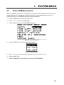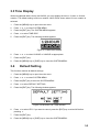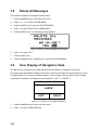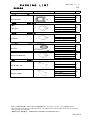
1
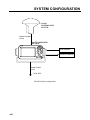
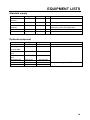
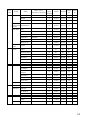
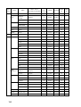
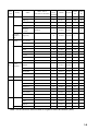
Back
OPERATOR'S MANUAL
NAVTEX RECEIVER
MODEL
NX-300
www.furuno.com
The paper used in this manual
is elemental chlorine free.
・FURUNO Authorized Distributor/Dealer
9-52 Ashihara-cho,
Nishinomiya, 662-8580, JAPAN
All rights reserved.
Printed in China
A : MAR . 2000
L : MAY 25, 2012
Pub. No. OME-56290-L
(REFU )
NX-300
*00017195012*
*00017195012*
* 0 0 0 1 7 1 9 5 0 1 2 *
IMPORTANT NOTICES
General
•
This manual has been authored with simplified grammar, to meet the needs of
international users.
•
The operator of this equipment must read and follow the descriptions in this manual.
Wrong operation or maintenance can cancel the warranty or cause injury.
•
•
•
•
Do not copy any part of this manual without written permission from FURUNO.
•
•
•
If this manual is lost or worn, contact your dealer about replacement.
The contents of this manual and equipment specifications can change without notice.
The example screens (or illustrations) shown in this manual can be different from the
screens you see on your display. The screens you see depend on your system
configuration and equipment settings.
Save this manual for future reference.
Any modification of the equipment (including software) by persons not authorized by
FURUNO will cancel the warranty.
All brand and product names are trademarks, registered trademarks or service marks of
their respective holders.
How to discard this product
Discard this product according to local regulations for the disposal of industrial waste. For
disposal in the USA, see the homepage of the Electronics Industries Alliance
(http://www.eiae.org/) for the correct method of disposal.
How to discard a used battery
Some FURUNO products have a battery(ies). To see if your product has a battery, see the
chapter on Maintenance. Follow the instructions below if a battery is used. Tape the + and terminals of battery before disposal to prevent fire, heat generation caused by short circuit.
In the European Union
The crossed-out trash can symbol indicates that all types of
batteries must not be discarded in standard trash, or at a trash
site. Take the used batteries to a battery collection site
according to your national legislation and the Batteries Directive
2006/66/EU.
Cd
In the USA
The Mobius loop symbol (three chasing arrows) indicates that
Ni-Cd and lead-acid rechargeable batteries must be recycled.
Take the used batteries to a battery collection site according to
local laws.
Ni-Cd
Pb
In the other countries
There are no international standards for the battery recycle symbol. The number of symbols
can increase when the other countries make their own recycling symbols in the future.
i
SAFETY INSTRUCTIONS
Safety Instructions for the Operator
WARNING
Do not open the cover of
the equipment.
Only qualified personnel
should work inside the
equipment.
CAUTION
Keep heater away from equipment.
A heater can melt the equipment's power
cord, which can cause fire or electrical
shock.
Use the proper fuse.
Immediately turn off the power at the
ship's mains switchboard if water or
foreign object falls into the equipment
or the equipment is emitting smoke or
fire.
Continued use of the equipment can cause
fire, electrical shock and serious injury.
Do not disassemble or modify the
equipment.
Fire, electrical shock or serious injury can
result.
ii
Use of the wrong fuse can cause fire or
equipment damage.
Do not operate the equipment with wet
hands.
Electrical shock can result.
Safety Instructions for the Installer
CAUTION
WARNING
Do not open the cover
unless totally familiar with
electrical circuits and
service manual.
Improper handling can result
in electrical shock.
Turn off the power at the ship's mains
switchboard before beginning the
installation. Post a warning sign near
the switchboard to ensure that the
power will not be applied while the
equipment is being installed.
Serious injury or death can result if the
power is not turned off, or is applied while
the equipment is being installed.
Ground the equipment to
prevent mutual interference.
Confirm that power supply voltage
is compatible with the voltage rating
of the equipment.
Connection to the wrong power supply can
cause fire or equipment damage. The
voltage rating appears on the label at the
rear of the equipment.
Observe the following compass safe
distances to prevent interference to a
magnetic compass:
NX-300
Standard
compass
Steering
compass
0.5 m
0.3 m
iii
CONTENTS
FOREWORD ................................................................................................................... vi
A Word to NX-300 Owners .................................................................................................................. vi
Features ............................................................................................................................................. vii
SYSTEM CONFIGURATION ........................................................................................ viii
EQUIPMENT LISTS........................................................................................................ ix
1. PRINCIPLE OF NAVTEX SYSTEM.........................................................................1-1
1.1 How NAVTEX Works ..................................................................................................................1-1
1.2 NAVTEX System Operation........................................................................................................1-1
1.3 Message Format.........................................................................................................................1-2
1.4 Display Indications......................................................................................................................1-3
1.5 NAVTEX Station Map .................................................................................................................1-4
1.6 NAVTEX Station List...................................................................................................................1-5
2. OPERATION ............................................................................................................2-1
2.1 Control Description .....................................................................................................................2-1
2.2 Turning the Power On/Off...........................................................................................................2-1
2.3 Adjusting Dimmer and Contrast..................................................................................................2-2
2.4 Menu Operation Overview..........................................................................................................2-2
2.5 Selecting Stations .......................................................................................................................2-3
2.6 Selecting Messages ...................................................................................................................2-4
2.7 Setting Functions (FUNCTIONS menu) .....................................................................................2-5
2.8 Selecting Language....................................................................................................................2-9
2.9 Displaying Messages..................................................................................................................2-9
2.10 Sample Messages ..................................................................................................................2-10
2.11 Displaying Navigation Data .................................................................................................... 2-11
2.12 Selecting Receive Frequency.................................................................................................2-12
3. SYSTEM MENU.......................................................................................................3-1
3.1 Units of Measurement ................................................................................................................3-1
3.2 Time Difference (using local time) ..............................................................................................3-2
3.3 Time Display...............................................................................................................................3-3
3.4 Default Setting ............................................................................................................................3-3
iv
3.5 Delete All Messages ...................................................................................................................3-4
3.6 User Display of Navigation Data.................................................................................................3-4
4. OTHER FUNCTIONS...............................................................................................4-1
4.1 DEMO Mode...............................................................................................................................4-1
4.2 VIEW Mode ................................................................................................................................4-1
4.3 All Clear ......................................................................................................................................4-1
4.4 Changing Received Message Log Window .................................................................................4-2
5. MAINTENANCE & TROUBLESHOOTING .............................................................5-1
5.1 Maintenance ...............................................................................................................................5-1
5.2 Diagnostic Test ...........................................................................................................................5-1
5.3 When the Battery Icon Appears..................................................................................................5-2
5.4 Replacement of Fuse .................................................................................................................5-3
6. INSTALLATION .......................................................................................................6-1
6.1 Installation of Display Unit ..........................................................................................................6-1
6.2 Installation of Antenna Unit.........................................................................................................6-2
6.3 Wiring .........................................................................................................................................6-3
6.4 Interfacing...................................................................................................................................6-4
MENU TREE ..............................................................................................................AP-1
SPECIFICATIONS ..................................................................................................... SP-1
PACKING LIST ............................................................................................................ A-1
OUTLINE DRAWINGS................................................................................................. D-1
INTERCONNECTION DIAGRAM ................................................................................ S-1
INDEX ................................................................................................................... index-1
Declaration of Conformity
v
FOREWORD
A Word to NX-300 Owners
Congratulations on your choice of the FURUNO NX-300 NAVTEX Receiver. We are confident
that you will enjoy many years of operation with this fine piece of equipment.
Since 1948, FURUNO Electric Company has enjoyed an enviable reputation for quality and
reliability throughout the world. Our extensive global network of agents and dealers furthers this
dedication to excellence.
The NX-300 is just one of the many FURUNO developments in the field of marine radio
communication. The NX-300 provides cost-effective price, high sensitivity and simple operation
in one compact and light-weight unit. In addition to its fundamental function of receiving
NAVTEX broadcasts, this unit can also function as nav data display when connected to
navigation equipment.
This unit is designed and constructed to ensure the user many years of trouble-free operation.
To obtain full performance from the equipment, however, you should carefully read and follow
the recommended procedures for installation, operation and maintenance. No machine can
perform its intended functions unless it is installed and maintained properly.
Thank you for considering and purchasing FURUNO equipment.
For SOLAS vessels and ships
Subject to formal inspection we recommend our NX-700 NAVTEX Receiver which meets the full
requirements of IMO Resolution MSC.148(77).
vi
Features
NAVTEX (Navigational Telex) is a worldwide coastal telex broadcasting system. Coastal
NAVTEX broadcasting stations with specific ID's transmit Navigational warnings, Meteorological
warnings, Search and Rescue (SAR) information and other navigational information for
NAVTEX receiver-equipped vessels sailing in coastal waters.
The FURUNO NX-300 NAVTEX receiver receives NAVTEX messages and automatically
displays them together with station ID and message category information.
The service range of a NAVTEX station is typically 200-400 nautical miles. A NAVTEX station
normally broadcasts every 4 hours.
The NAVTEX message is relevant for all types and sizes of vessels. The NX-300 is shipped
from the factory equipped to receive 7 specific types of NAVTEX messages from all NAVTEX
stations. However unnecessary stations can be rejected or necessary stations can be added by
the "manual station selection" facility.
If ship's position data is fed from navigation equipment, the NX-300 automatically decides in
which NAVAREA the vessel is navigating, and selects stations. (NAVAREAs are geographical
zones defined by the International Maritime Organization.)
• Unattended operation once required data is entered.
• Received data is not saved nor displayed when the error rate exceeds the percentage you set
(max 39%).
• No paper required
• Designed for voluntary carriage on recreational craft and small workboats
• Compact, stylish display and antenna units
• Memory of up to 28,000 characters for last 72 hours
• Navigation data can be fed through external input (connection with navigation aid required).
• Bright 95 x 60 mm LCD with adjustable contrast and brilliance
• Memory backup with a long-life lithium battery
• Low power consumption
vii
SYSTEM CONFIGURATION
H-field
ANTENNA UNIT
NX-3H-D
Antenna Cable
(10 m)
NAVTEX RECEIVER
NX-300-D
FURUNO
MENU
ENT
DISP
DIM
FREQ
PWR
Power Cable
(2 m)
12-24 VDC
NX-300 System configuration
viii
GPS navigator
Personal Computer
EQUIPMENT LISTS
Standard supply
Name
NAVTEX
Receiver
Antenna Unit
Installation
Materials
Spare Parts
Accessories
Type
NX-300-D
Code No.
-
NX-3H-D
CP08-02200
000-015-917
SP08-02401
FP14-02801
001-072-500
001-057-060
Qty
1
Remarks
Including hanger and knob bolts
1
H-field type with 10 m cable
1 set w/inst. mat. CP08-02201,
cable assy.: MJ-A7SPF0009-020C
1 set Fuse: FGMB 125V 1A PBF, 2pcs.
1 set Hard cover: 20-016-1091
Optional equipment
Name
Antenna Unit
Right Angle
Antenna Base
L-angle Antenna
Base
Handrail Antenna
Base
Mast Mount Kit
Flush Mount Kit S
Flush Mount Kit F
Type
NX-3H-D
No.13-QA330
Code No.
001-111-910-10
No.13-QA310
001-111-900-10
No.13-RC5160
001-111-920-10
CP20-01111
OP20-17
OP20-29
004-365-780
000-040-720
000-041-405
Remarks
H-field type with 10 m cable
For antenna unit
For flush mounting the NAVTEX receiver
ix
This page intentionally left blank.
x
1. PRINCIPLE OF NAVTEX SYSTEM
1.1
How NAVTEX Works
There are many types of navigational and meteorological information available on radio, such
as NAVAREA, HYDROPAC, etc. However, these systems rely heavily upon the operator's
experience and skill in tuning the radio and interpreting messages. In addition, constant
monitoring to pick up wanted information among a vast volume of messages is not practical with
a limited radio staff.
To provide all mariners with up-to-the-minute information automatically, the NAVTEX system
was developed.
NAVTEX is an acronym meaning Navigational Telex, and as its name shows, it is a kind of
narrow band radio teletype system for sending (by frequency shift keying) text messages
expressed in a 7-unit code. The difference is that a NAVTEX transmitter transmits nine control
characters (header code) ahead of the main message, so that the receiver can identify the
station, message type and serial number automatically.
1.2
NAVTEX System Operation
For navigation purposes, the world is divided into 16 areas (called Navareas) as shown in the
figure below. Each Navarea has multiple NAVTEX stations and each NAVTEX station has an
identification code, from "A" to "Z." The frequency assigned to NAVTEX is only one (518 kHz),
and many stations exist in the same Navarea. (Some stations use 490 kHz also.)
Figure 1-1 NAVTEX area
If the stations were to transmit without any rule, the system would collapse due to mutual
interference. To avoid this problem, the following rules apply.
• The transmission schedule is determined so that two or more stations having a common
service area may not overlap in time.
• Each station transmits with minimum required power to cover its service area (200 nautical
miles nominal).
1-1
1.3 Message Format
For automatic identification of messages, each message starts with eight control characters,
called "Header codes".
The first four characters are always "ZCZC" and common to all messages. This part is used for
message synchronization. The latter four characters are designated as b1, b2, b3 and b4 to
indicate origin, category and serial number of the message.
Character b1 is the identification letter of the NAVTEX station; "A" to "Z". Character b2 indicates
the type of message, "A" to "Z", as listed below. Character b3 and b4 indicate the serial number
of the message. The serial numbers are counted up from "01" to "99", and start from "01" again.
Number "00" is specially reserved for important emergency messages, such as a search and
rescue (SAR) message.
The end of each message is indicated by "NNNN" (four successive N's).
General message format is summarized below.
Header code
ZCZC b1 b2 b3 b4
main message
Start code
(sync)
Main message
NNNN
Termination code
Serial number
"00": Emergency message
"01" - "99": Normal message
Type of message
"A" - "Z"
(See the list below.)
Station ID
"A" - "Z"
[Type of message (category)]
A:
Navigational warning
I:
OMEGA message
B:
Meteorological warning
J:
Differential OMEGA message
C:
Ice report
K:
D:
Search and rescue information/
piracy and armed robbery
Other electronic navigational aid
system message
L:
Navigational warning (additional)
E:
Meteorological forecast
M to U: Reserve-presently not used
F:
Pilot message
V:
G:
DECCA message
W to Y Reserve-presently not used
H:
LORAN-C message
Z:
1-2
Notice to Fishermen (U. S. only)
QRU (no message on hand)
1.4
Display Indications
SAR: Displayed when
message type D is
displayed.
NEW: Displayed when
message is displayed for
the first time.
AUTO: Displayed when you
select AUTO mode in
STATION SELECTION.
Rx: Lights when message
is being received.
SAR receiving: Lights (and
the alarm sounds) when
message type D is being
received. Hitting any key
silences the alarm.
WARNING: Appears when message
type A, B or L is displayed.
WARNING receiving: Lights (and the
alarm sounds) when message type A,
B or L is received. Hitting any key
silences the alarm.
BATTERY icon: Displayed
when the battery voltage is
low.
Scroll bar: Shows location
in message displayed.
Figure 1-2 Display indications
1-3
1.5
1-4
NAVTEX Station Map
1.6
NAV
area
I
NAVTEX Station List
Country
Station
Station Name
(Less than 18 characters)
Name
Latitude
Longitude
Characters
518kHz
490kHz
B1
B1
Belgium
Oostende
8
51 11 N
02 48 E
M,T
Estonia
Tallinn
7
59 30 N
24 30 E
E,U
Iceland
Reykjavik Radio
15
64 05 N
21 51 W
R,X
Ireland
Valencia
8
51 27 N
09 49 W
W
Malin Head
10
55 22 N
07 21 W
Q
Niton
5
50 35 N
01 18 W
K
10
52 06 N
04 15 E
P
Bodo Radio
10
67 16 N
14 23 E
B
Rogaland Radio
14
58 48 N
05 34 E
L
Vardoe Radio
12
70 22 N
31 06 E
V
Svalbard
8
78 04 N
13 38 E
A
France
Netherlands
Norway
Netherlands Coast
Guard
Valentia
Den Helder
R
Ørlandet
Orlandet
8
63 40 N
09 33 E
N
Harnosand
Bjuroklubb
10
64 28 N
21 36 E
H
Karlskrona
Gislovshammar
13
55 29 N
14 19 E
J
15
59 16 N
18 43 E
U,D
8
57 06 N
12 23 E
D
Cullercoats
11
55 02 N
01 26 W
G
I,U
Portpatrick
11
54 51 N
05 07 W
O
C
Niton
5
50 35 N
01 18 W
K,S,E
A,I
Oostende
8
51 11 N
02 48 E
M
Murmansk
8
68 58 N
33 05 E
C
Archangel
9
64 33 N
40 32 E
F
Cameroon
Douala
6
N.I.
N.I.
N.I.
Cape Verde
Sao Vicente Radio
17
N.I.
N.I.
N.I.
France
Cross Corsen
12
48 28 N
05 03 W
A
Niton
5
50 35 N
01 18 W
Mauritania
Nouadhibou Radio
16
N.I.
N.I.
N.I.
Morocco
Casablanca Radio
16
33 36 N
07 38 W
M
Portugal
Horta Radio
Horta
5
38 32 N
28 38 W
F
J
Monsanto Radio
Monsanto
8
38 44 N
09 11 W
R
G
Corunna
Coruna
6
43 21 N
08 27 W
D
Sweden
Stockholm Radio
Gothenburg
(Grimeton)
United
Kingdom
Russian
Federation
II
Station
Spain
Grimeton
E
T
(Con’t on next page)
1-5
NAV
Country
area
II
III
Spain
Station Name
(Less than 18 characters)
Station
Name
Latitude
Longitude
Characters
518kHz
490kHz
B1
B1
Tarifa
6
36 01 N
05 34 W
G
Las Palmas
10
28 10 N
15 25 W
I
Bulgaria
Varna
5
43 04 N
27 46 E
J
Croatia
Split
Split radio
11
43 30 N
16 29 E
Q
Cyprus
Cyprus
Cypradio
8
35 03 N
33 17 E
M
Egypt
Alexandria
10
31 12 N
29 52 E
N
Serapeum
8
30 28 N
32 22 E
X
France
Cross La Garde
Toulon
6
43 06 N
05 59 E
W
Greece
Heraklion
Iraklion
8
35 20 N
25 07 E
H
Corfu
Kerkyra
7
39 37 N
19 55 E
K
Lemnos
Limnos
6
39 52 N
25 04 E
L
Israel
Haifa
5
32 49 N
35 00 E
P
Italy
Roma
4
41 48 N
12 31 E
R
Augusta
7
37 14 N
15 14 E
S,V
Cagliari
8
39 14 N
09 14 E
T
Trieste
7
45 41 N
13 46 E
U
Malta
5
35 49 N
14 32 E
O
Novorossiysk
12
44 42 N
37 44 E
A
Astrakhan
9
46 18 N
47 58 E
W
Spain
Cabo de la Nao
14
38 43 N
00 09 E
X
Turkey
Istanbul
8
41 04 N
28 57 E
D
Samsun
6
41 17 N
36 20 E
E
Antalya
7
36 53 N
30 42 E
F
Izmir
5
38 22 N
26 36 E
I
Mariupol
8
47 06 N
37 33 E
B
Odessa
6
46 29 N
30 44 E
C
Bermuda
7
32 23 N
64 41 W
B
Malta
Russian
Federation
Ukraine
IV
Station
Bermuda
(UK)
Canada
Sept Iles
Riviere-au-Renard
17
50 11 N
66 07 W
C,D
Prescott
Wiarton
7
44 20 N
81 10 W
H
St. Johns
9
47 30 N
52 40 W
O
Thunder Bay
11
48 25 N
89 20 W
P
10
46 10 N
60 00 W
Q,J
8
43 45 N
66 10 W
U,V
Sydney, Nova
Scotia
Yarmouth
Sydney, NS
S
(Con’t on next page)
1-6
NAV
area
IV
Country
Canada
Station
Station Name
(Less than 18 characters)
Station
Name
Latitude
Longitude
Characters
518kHz
490kHz
B1
B1
Montreal
8
45 41 N
73 16 W
W,T
Labrador
8
53 42 N
57 01 W
X
Iqaluit, NU
11
63 43 N
68 33 W
T
14
64 04 N
52 01 W
W
Miami
5
25 37 N
80 23 W
A
Boston
6
41 43 N
70 30 W
F
New Orleans
11
29 53 N
89 57 W
G
S
Denmark
(Greenland-We Godthaab(Nuuk)
st Coast)
United States
Chesapeake
Portsmouth
10
36 43 N
76 00 W
N
San Juan
Isabella
8
18 28 N
67 04 W
R
Savannah, GA
12
32 08 N
81 42 W
E
Curacao
7
12 10 N
68 52 W
H
Colonia
7
N.I.
N.I.
N.I.
Laguna del Sauce
16
N.I.
N.I.
N.I.
La Paloma
9
34 40 S
54 09 W
F
Montevideo
10
34 52 S
56 19 W
N.I.
Punta del Este
14
34 58 S
54 57 W
N.I.
Salto
5
N.I.
N.I.
N.I.
Ushaia
6
54 48 S
68 18 W
A,M
Rio Gallegos
12
51 37 S
65 03 W
B,N
18
45 51 S
67 25 W
C,O
Bahia Blanca
12
38 43 S
62 06 W
D,P
Mar del Plata
14
38 03 S
57 32 W
E,Q
Buenos Aires
12
34 36 S
58 22 W
F,R
Uruguay
La Paloma
9
34 40 S
54 09 W
F
Namibia
Walvis Bay
10
23 03 S
14 37 E
B
South Africa
Cape Town
9
33 40 S
18 43 E
C
Port Elizabeth
14
34 02 S
25 33 E
I
Durban
6
30 00 S
31 30 E
O
6
19 05 N
72 50 E
G
Madras
6
13 08 N
80 10 E
P
Mauritius Radio
15
20 10 S
57 28 E
C
Netherlands
Antilles
V
VI
Uruguay
Argentina
Comodoro
Rivadavia
VII
VIII
India
Mauritius
Bombay
Mumbay
A
A
(Con’t on next page)
1-7
NAV
518kHz
490kHz
B1
B1
6
26 09 N
50 28 E
B
Serapeum
8
30 28 N
32 22 E
X
Kosseir
7
26 06 N
34 17 E
V
Bushehr
7
28 59 N
50 50 E
A
Bandar Abbas
12
27 07 N
56 04 E
F
Saudi Arabia
Jeddah
6
21 23 N
39 10 E
H
Oman
Muscat
6
23 36 N
58 30 E
M
Pakistan
Karachi
7
24 51 N
67 03 E
P
Bahrain
Egypt
Station
Iran
(Less than 18 characters)
Hamala
Serapeum
(Ismailia)
Quseir
X
XI
Station
Longitude
area
IX
Station Name
Latitude
Country
Name
Characters
0
China
Indonesia
Japan
Korea,
NONE
Sanya
5
18 14 N
109 30 E
M
Guangzhou
9
23 08 N
113 32 E
N
Fuzhou
6
26 01 N
119 18 E
O
Shanghai
8
31 08 N
121 33 E
Q
Dalian
6
38 52 N
121 31 E
R
Jayapura
8
02 31 S
140 43 E
A
Ambon
5
03 42 S
128 12 E
B
Makassar
8
05 06 S
119 26 E
D
Jakarta
7
06 06 S
106 54 E
E
Otaru
5
43 19 N
140 27 E
J
Kushiro
7
42 57 N
144 36 E
K
Yokohama
8
35 14 N
139 55 E
I
Moji
4
34 01 N
130 56 E
H
Naha
4
26 05 N
127 40 E
G
Chukpyun
Chukpyong
9
37 03 N
129 26 E
V
J
Pyonsan
Pyongsan
8
35 36 N
126 29 E
W
K
Penang
6
05 26 N
100 24 E
U
Miri
4
04 28 N
114 01 E
T
Sandakan
8
05 54 N
118 00 E
S
Manila
6
14 35 N
121 03 E
J
Puerto Princesa
15
09 44 N
118 43 E
I
Davao
5
07 04 N
125 36 E
K
Singapore
Singapore
9
01 25 N
103 52 E
C
Thailand
Bangkok Radio
13
13 43 N
100 34 E
F
United States
Guam
4
13 29 N
144 50 E
V
Republic of
Malaysia
Philippines
(Con’t on next page)
1-8
NAV
area
XI
Country
Vietnam
Taiwan
Station
Station Name
(Less than 18 characters)
Station
Name
Latitude
Longitude
518kHz
490kHz
B1
B1
Characters
Ho Chi Minh City
16
10 47 N
106 40 E
X
Haiphong
8
20 44 N
106 44 E
P,W
Danang
6
16 05 N
108 13 E
W,P,K
Chilung
7
25 09 N
121 44 E
P
9
22 29 N
120 25 E
Hong Kong
9
22 13 N
114 15 E
L
Prince Rupert
13
54 20 N
130 20 W
D
Tofino
6
48 55 N
125 35 W
H
San Francisco
13
37 55 N
122 44 W
C
Kodiak
6
57 46 N
152 34 W
J,X
Honolulu
8
21 22 N
158 09 W
O
Cambria
7
35 31 N
121 03 W
Q
Astoria
7
46 10 N
123 49 W
W
Adak
4
51 54 N
176 38 W
X
Kholmsk
7
47 02 N
142 03 E
B
Murmansk
8
68 46 N
32 58 E
C
Arkhangelsk
11
64 51 N
40 17 E
F
Astrakhan
9
45 47 N
47 33 E
W
Kaohsiung
(Linyüan)
Kaohsiung
W
P
Associate
Member of
IMO
XII
Canada
United States
XIII
Russian
Federation
XIV
XV
XVI
0
Chile
Peru
Ecuador
NONE
Antofagasta
11
23 40 S
70 25 W
A,H
Valparaiso
10
32 48 S
71 29 W
B,I
Talcahuano
10
36 42 S
73 06 W
C,J
Puerto Montt
12
41 30 S
72 58 W
D,K
Punta Arenas
12
53 09 S
70 58 W
E,L
Isla de Pascua
14
27 09 S
109 25 W
F,G
Paita
5
05 05 S
81 07 W
S
Callao
6
12 03 S
77 09 W
U
Mollendo
8
17 01 S
72 01 W
W
Guayaquil
9
02 17 S
79 52 W
M
Note: The list shows the stations listed at Longwave Navtex Broadcasts (2004).
1-9
This page is intentionally left blank.
1-10
2. OPERATION
2.1 Control Description
All operation of the NX-300 is carried out with the controls on the front panel of the display unit.
FURUNO
MENU
ENT
DISP
DIM
Omnipad
• Shifts cursor and display.
• Selects items on menus.
PWR
Removing the hard cover
To remove the hard cover, squeeze
it at its top and bottom right (or left)
corners and pull it toward you.
Pressure
Opens menu or
message display.
Opens message
selecting display
or navigational
data display.
MENU
ENT
Registers items on menus.
DISP
DIM
Adjusts panel dimmer
and contrast.
Selects 518 kHz or 490 kHz.
(See page 2-12.)
FREQ
PWR
Long press: Turns power off.
Touch and release: Turns power on.
Pressure
Figure 2-1 Control panel
2.2 Turning the Power On/Off
Turning on: Press the [PWR] key. “NO MESSAGE” (message waiting screen) appears. When a
message is received, it appears on the screen and in case of a long message, it scrolls
continuously.
To confirm version number of the equipment, press the [PWR] key a little longer. Release the
key when the following window appears.
XX-Version no.
Figure 2-2 TURNING ON window
Turning off: Press the [PWR] key for 3 seconds.
Figure 2-3 TURNING OFF window
Note: The NX-300 should be turned on for the duration of a voyage so that important warning
messages will not be missed.
2-1
2.3 Adjusting Dimmer and Contrast
1. Press the [DIM] key to show the dimmer and contrast setting window.
Figure 2-4 DIMMER and CONTRAST setting window
2. Press or for best illumination of the control panel and LCD.
3. Press or for best contrast of the LCD.
4. Press the [ENT] key to close the dimmer and contrast setting window.
Note: If you turn off the power with contrast less than 36, contrast is automatically set to 36
when you turn on the power again.
2.4 Menu Operation Overview
The menu allows you to custom tailor the NX-300 according to your needs. You can select
which categories of message you wish to receive, specify which data to display, etc.
1. Press the [MENU] key to open the main menu.
Figure 2-5 Main menu
Note: If you press the [MENU] key again at the main menu, the message waiting screen
appears.
2. Press or to select menu item. As you operate or , the selected item appears in
reverse video. For example, select FUNCTIONS.
3. Press the [ENT] key to open menu selected.
Figure 2-6 FUNCTIONS menu
2-2
4. Press ! or " to select menu item and press the [ENT] key. For example, select RCV ALARM.
Corresponding option menu appears.
Figure 2-7 ON/OFF window
5. Press ! or " to select option desired.
6. Press the [ENT] key to resister your selection.
7 Press the [MENU] key once to return to the menu or twice to quit the menu.
2.5
Selecting Stations
The STATION SELECTION menu allows you to select what stations to receive, automatically or
manually. In the AUTO mode stations are automatically selected according to the distance
between own ship and NAVTEX stations. External navigational data is required to use the AUTO
mode. If it is not input, all stations are selected. In the MANUAL mode you can select what
stations you wish to receive. Default setting is the AUTO mode.
1. Press the [MENU] key to open the main menu.
2. Press ! or " to select STATION SELECTION.
3. Press the [ENT] key. The MODE window appears.
Figure 2-8 MODE window
4. Press ! or " to select AUTO or MANUAL as desired.
5. For the AUTO mode, press the [ENT] key to close the menu.
For the MANUAL mode, do the following:
a) Press the [ENT] key. The STATION SELECTION menu appears.
Figure 2-9 STATION SELECTION menu
b)
c)
Press ! or " to select a station you want to change the current setting.
Press the [ENT] key to show the following window.
Figure 2-10 RECEIVE/IGNORE window
2-3
d)
e)
f)
g)
2.6
Press ! or " to select RECEIVE or IGNORE depending on whether you want to select or
deselect the station.
Press the [ENT] key.
Repeat steps b) to e) to select or deselect other stations.
Press the [MENU] key or [DISP] key to close the STATION SELECTION menu.
Selecting Messages
1.
Press the [MENU] key to open the main menu.
2.
Press ! or " to select MESSAGE SELECTION.
3.
Press the [ENT] key to show the MESSAGE SELECTION menu.
Figure 2-11 MESSAGE SELECTION menu
4.
Press ! or " to select a message you want to change the current setting.
5.
Press the [ENT] key to show the following window.
Figure 2-12 RECEIVE/IGNORE window
6.
When you change RECEIVE into IGNORE for message type A, B, D or L, the following
window appears to confirm. For all other message types proceed to step 8.
Figure 2-13 Ignore message window
7.
Press # or $ to select YES or NO. Select YES to change the current setting, or NO not to
change.
8.
Press the [ENT] key.
9.
Repeat steps 4 to 8 to select or deselect other message types.
10. Press the [MENU] key or [DISP] key to close the MESSAGE SELECTION menu.
2-4
2.7
Setting Functions (FUNCTIONS menu)
See menu description below for detailed information.
1.
Press the [MENU] key to open the main menu.
2.
Press ! or " to select FUNCTIONS.
3.
Press the [ENT] key to display the FUNCTIONS menu.
Figure 2-14 FUNCTIONS menu
4.
Press ! or " to select menu item and press the [ENT] key.
5.
Press ! or " to select option desired.
6.
Press the [ENT] key to register your selection.
7.
Press the [MENU] key twice to close the menu.
2.7.1
FUNCTIONS menu description
RCV NOTIFY: The raw NAVTEX signal can be monitored through the monitor speaker by turning
RCV NOTIFY on. The default setting is OFF.
RCV ALARM: The audible alarm may be generated when message type A, B, D or L is received.
The default setting is ON.
KEY BEEP: The equipment can emit a beep tone when a control is operated. The default setting
is ON.
ERROR RATE: When character error occurs due to noise interference during signal propagation,
erroneous character is displayed as “∗”.
Error Rate means character error rate and is calculated as followed:
Error Rate = number of erroneous characters ÷ total number of characters received × 100 (%)
(Total number of characters includes space, line feed, carriage returns, etc.)
When the character error rate is within the percentage you set (0-39%), the NX-300 displays the
message and stores it. When it exceeds the percentage you set, the NX-300 neither displays nor
stores the message. You may set the threshold level of character error rate as desired and the
default setting is 33%.
2-5
SCROLLING: This menu item lets you select how to scroll the message display. The default
setting is AUTO-SLOW.
AUTO-SLOW: Long press of ! or " scrolls line-by-line slowly automatically. Touch and
release " to scroll manually.
AUTO-FAST: Long press of ! or " scrolls line-by-line automatically, faster than AUTOSLOW. Touch and release " to scroll manually.
SKIP-$$:
The U.S. National Weather Service broadcasts weather information via the
U.S. Coast Guard NAVTEX stations. Their messages contain $$, the
continue indicator. You can quickly jump to the next continue indicator. Long
press of ! or " skips to $$.
SAVE MESSAGE TO PC: Select to download message to a PC. See the next paragraph.
2.7.2
Downloading Messages to a PC
Wiring
Your equipment provides a wiring diagram that shows how to connect to a PC using a DSUB 9pin connector. Refer to the interconnection diagram for details.
1.
Press the [MENU] key to open the main menu.
2.
Press ! or " to select SYSTEM MENU.
3.
Press the [ENT] key to show the SYSTEM MENU.
4.
Press " to select WIRING INFO?.
5.
Press the [ENT] key to show the wiring info display.
Figure 2-15 Connection to PC using a DSUB 9-pin connector
A DSUB 25-pin (EIA-232) may also be used to make the connection. In this case the wiring
diagram is as follows.
1
2
3
4
5
6
7
RD2
SG
SD
RD
+
FG
WHITE
BLUE
YELLOW
GREEN
RED
BLACK
-
+
7 GND
3 RXD
2 TXD
4 RTS
5 CTS
6 DSR
20 DTR
Figure 2-16 Connection to PC using a DSUB 25-pin connector
2-6
Setting for communication software on PC
Baud Rate:
Character Length:
Stop Bit:
Parity:
X Control:
4800 bps
8 bit
1 bit
None
XON/XOFF
Downloading messages to a PC
Set up the computer to receive data. Messages are downloaded to a PC character by character
during reception.
To download all messages saved in NX-300, do the following;
1.
Press the [MENU] key to open the main menu.
2.
Press ! or " to select FUNCTIONS.
3.
Press the [ENT] key to show the FUNCTIONS menu.
4.
Press " to select SAVE MESSAGE TO PC.
5.
Press the [ENT] key. The following display appears.
Figure 2-17 SAVE MESSAGE TO PC display
6.
Press the [ENT] key.
Figure 2-18 SAVING START window
7.
Set up the computer to receive data.
8.
Press # to select YES and press the [ENT] key.
2-7
9.
Press the [ENT] key to save. The following messages appear in order.
To cancel saving,
press the [ENT] key
Figure 2-19 SAVING MESSAGES window
10. Press any key to escape.
Note1: No message is received during downloading.
Note2: When a PC or a serial printer is connected to the NX-300, received messages are
displayed on a PC or printed on a serial printer but not displayed or saved to the NX-300 in the
following cases;
• The NX-300 receives a message it has already saved.
• A message is interrupted to receive.
2-8
2.8 Selecting Language
You can select language displayed on the NX-300. Languages are English, French, German,
Italian, Spanish, Dutch, Danish, and Portuguese.
1. Press the [MENU] key to open the main menu.
2. Press to select LANGUGE.
3. Press the [ENT] key. The following menu appears. (ENG: English, FRA: French, GER:
German, ITA: Italian, SPA: Spanish, DUT: Dutch, DEN: Danish, POR: Portuguese)
Figure 2-20 LANGUAGE menu
4. Use the Omnipad to select language desired.
5. Press the [ENT] key to register your selection and press the [MENU] key to close the menu.
2.9 Displaying Messages
The NX-300 automatically saves and stores up to 132 received messages (However, the
memory capacity is limited to 28,000 characters). If memory of the NX-300 is full, messages are
deleted on order of time.
1. Press the [DISP] key to show the received messages log. Messages (numbers) are
arranged in the order received from latest to earliest, Left to right.
The latest
message
Unread message
D type message
For A, B or L type
message
Figure 2-21 Received messages log
2. Operate the Omnipad to select the message to display. If more than 15 messages are
saved, the scroll bar appears at the rigth side of the display. Press or to scroll the
display.
3. Press the [ENT] key to display the message selected.
Note: If you want to see the received frequency (518 kHz or 490 kHz) also, change the window
mode as shown on page 4-2.
2-9
2.10
Sample Messages
When message is displayed, press ! or " to scroll message and press # or $ to display the
other message. When the oldest or newest message is displayed, the beep sounds.
ID no.
Display indications
Start code (sync)
Scroll bar
Main message
Press " to scroll.
Main message
Termination code
Figure 2-22 Sample messages
2-10
2.11 Displaying Navigation Data
With navigation data input the NX-300 can display navigation data, in addition to its primary
function.
1. Press the [DISP] key to display the receiving messages log.
2. Press the [DISP] key again to display navigation data.
Figure 2-23 Nav data display
3. To return to the receiving message log, press the [DISP] key again.
2-11
2.12 Selecting Receive Frequency
1. Press the [FREQ] key to show the frequency window.
(Default setting is 518 kHz)
Figure 2-24 Frequency window
2. Press or to select receive frequency as appropriate.
3. Press the [ENT] key to close the frequency window.
2-12
3. SYSTEM MENU
3.1
Units of Measurement
When navigational data is fed to the NX-300, you can select units of distance and speed to use.
Distance/speed can be displayed in nautical miles/knots, kilometers/kilometers per hour, or
miles/ miles per hour. The default setting is nautical miles/knots.
1.
Press the [MENU] key to open the main menu.
2.
Press ! or " to select SYSTEM MENU.
3.
Press the [ENT] key. The SYSTEM MENU appears.
Figure 3-1 SYSTEM MENU
4.
Press the [ENT] key. The following window appears.
Figure 3-2 UNITS window
5.
Press ! or " to select combination desired; nm, kt; km, km/h; mi, mi/h.
6.
Press the [ENT] key.
7.
Press the [MENU] key or [DISP] key to close the SYSTEM MENU.
3-1
3.2
Time Difference (using local time)
GPS uses UTC time. If a GPS receiver feeds nav data to the NX-300 and you would rather use
local time, enter the time difference (range: -13:30 to +13:30) between local time and UTC time.
1.
Press the [MENU] key to open the main menu.
2.
Press ! or " to select SYSTEM MENU.
3.
Press the [ENT] key to open the SYSTEM MENU.
Figure 3-3 SYSTEM MENU
4.
Press " to select TIME DIFF.
5.
Press the [ENT] key. A cursor circumscribes + or -. This cursor appears whenever selected
data can be changed with Omnipad.
6
Press ! or " to display + or -.
7.
Press $ to move the cursor to the next column.
8.
Press ! or " to select number desired.
9.
Repeat steps 7 and 8 to complete.
10.
Press the [ENT] key.
11.
Press the [MENU] key or [DISP] key to close the SYSTEM MENU.
3-2
3.3 Time Display
When navigational data is fed to the NX-300, you may display the time in 12-hour or 24-hour
notation. The default setting is 24-hour notation. AM or PM is shown when 12-hour notation is
selected.
1.
Press the [MENU] key to open the main menu.
2.
Press ! or " to select SYSTEM MENU.
3.
Press the [ENT] key. The SYSTEM MENU appears.
4.
Press " to select TIME DISP.
5.
Press the [ENT] key. The following window appears.
Figure 3-4 TIME DISP window
6.
Press ! or " to select 12HOUR or 24HOUR as appropriate.
7.
Press the [ENT] key.
8.
Press the [MENU] key or [DISP] key to close the SYSTEM MENU.
3.4
Default Setting
This function restores all default settings.
1.
Press the [MENU] key to open the main menu.
2.
Press ! or " to select SYSTEM MENU.
3.
Press the [ENT] key to show the SYSTEM MENU.
4.
Press " to select DEFAULT SETTING.
5.
Press the [ENT] key. The following window appears.
Figure 3-5 DEFAULT SETTING window
6.
Press # to select YES. If you want to cancel, press the [ENT] key to select NO before
pressing #.
7.
Press the [ENT] key.
8.
Press the [MENU] key or [DISP] key to close the SYSTEM MENU.
3-3
3.5
Delete All Messages
This function deletes all messages NX-300 saves.
1.
Press the [MENU] key to open the main menu.
2.
Press ! or " to select SYSTEM MENU.
3.
Press the [ENT] key to show the SYSTEM MENU.
4.
Press " to select DELETE ALL MESSAGES.
5.
Press the [ENT] key. The following window appears.
Figure 3-6 DELETE ALL MESSAGES window
6.
Press # to select YES.
7.
Press the [ENT] key.
8.
Press the [MENU] key or [DISP] key to close the SYSTEM MENU.
3.6
User Display of Navigation Data
The NX-300 can function as nav data display when connected to navigation equipment.
You may choose what data to display in the three cells below the date and time indications on the
nav data display. The choices of data are speed, course, range, bearing, power source voltage
and position in latitude and longitude (not available for “LEFT” or “RIGHT”).
01-JAN-00
15:37:40
LARGE
LEFT
RIGHT
Figure 3-7 Location of nav data indications
1.
Press the [MENU] key to open the main menu.
2.
Press " to select USER DISPLAY.
3-4
3.
Press the [ENT] key to show the USER DISPLAY menu. The cursor is now on the LARGE
field. LARGE means the center indication on the nav data display.
Figure 3-8 USER DISPLAY
4.
Press the [ENT] key. The following window appears.
Figure 3-9 Options for LARGE window
5.
Operate the Omnipad to select item desired. (SPD: Speed, CSE: Course, RNG: Range to
destination, BRG: Bearing to destination, PWR: Power source voltage, L/L: position in
latitude and longitude)
6.
Press the [ENT] key.
7.
Select the items LEFT and RIGHT and set their options like you did for LARGE, referring to
Figure 3-12 for location of indications.
Figure 3-10 Options for LEFT, RIGHT
8.
Press [DISP] key twice to display the navigation data.
The figure below shows display appearance for the setting shown in Figure 3-8.
Figure 3-11 Nav data display
3-5
This page is intentionally left blank.
3-6
4. OTHER FUNCTIONS
4.1 DEMO Mode
The DEMO mode provides simulated operation of this unit. Connection of antenna is not
necessary. You may select stations and messages manually or automatically and demo
messages are received. All controls are operative.
Note: Turning on the DEMO mode erases all messages.
Press the [PWR] key while pressing to turn the power on. “SET DEMO MODE!” appears
momentarily. “DEMO” appears at the top of the screen when the DEMO mode is active.
DEMO mark
Figure 4-1 Message display
To escape the DEMO mode, press the [PWR] key while pressing . “RESET DEMO MODE!”
appears momentarily.
4.2 VIEW Mode
The NX-300 ordinarily displays messages in their entirety. The VIEW mode, however displays
messages character by character.
Press the [PWR] key while pressing to turn the power on. “SET VIEW MODE!” appears
momentarily. “VIEW” is displayed at the upper left corner of the display.
To quit the VIEW mode,: repeat above procedure. “RESET VIEW MODE!” appears.
4.3 All Clear
This function deletes all messages and restores default settings. When the NX-300 is first
installed, you should clear all data.
Press the [PWR] key while pressing to turn the power on. “RESET BACKUP DATA!” appears
momentarily while data is being cleared. Then, all default settings are restored.
4-1
4.4 Changing Received Message Log Window
You can show received frequency on the received message log as shown below.
1. Press the [PWR] key while pressing !to turn the power on and release the keys after
display appears.
2. Press the [DISP] key to show the received message log. The received frequencies (518 kHz
and 490 kHz) are displayed on the window.
Figure 4-2 Received message log
3. To restore it, do step 1.
4-2
5. MAINTENANCE &
TROUBLESHOOTING
WARNING
Do not open the equipment.
Only qualified personnel should work inside
the equipment. Further, watertightness may
be reduced.
5.1
Maintenance
Check the following points regularly to maintain performance:
• Check that connectors on the rear panel are firmly tightened and free of rust.
• Check that the ground system is free of rust and the ground wire is tightly fastened.
• Check that battery terminals are clean and free of rust.
• Check the antenna for damage. Replace if damaged.
• Dust and dirt on the keyboard and display screen may be removed with a soft cloth. Do not
use chemical cleaners to clean the equipment; they may remove paint and markings.
5.2
Diagnostic Test
The diagnostic test checks ROM, RAM, data port, battery, keyboard and LCD for proper
operation and displays program numbers.
1.
Press the [MENU] key to open the main menu.
2.
Press the ! or " to select SYSTEM MENU.
3.
Press the [ENT] key to show the SYSTEM MENU.
4.
Press ! or " to select TEST.
5.
Press the [ENT] key. You are asked if you are ready to start the test.
Figure 5-1 TEST window
6.
Press the # to select YES.
5-1
7.
Press the [ENT] key to start the test. The equipment checks ROM, RAM, SIO and internal
battery, and the results are individually displayed as OK or NG (No Good). Program
numbers appear at the bottom of the display. If any NG is displayed, contact your dealer.
Note 1: SIO requires a special connector to check. “03” appears as the result when no
connector is connected.
Note 2: CNT is the number of times test has been consecutively executed.
0850191-XX.XX
1451414-XX.XX
XX: Program version no.
Figure 5-2 TEST display
After the equipment has checked the items shown in Figure 5-2, a beep sounds and the
message PUSH KEY appears at the top right-hand corner.
8.
Press each key one by one. The name of the key pressed momentarily appears at the top
of right-hand corner if the key is functioning properly.
Note: If no key is pressed within approx. five seconds, the equipment automatically
displays the following message to inform you that it is now going to check the LCD.
Figure 5-3 LCD CHECK display
9.
The test repeats. Turn off the power to stop the test.
5.3 When the Battery Icon Appears
A lithium battery (type: CR2354-1F2, code no.: 000-142-305) is installed on the circuit board
inside the display unit, and it preserves data when the power is turned off. The life of the battery
is about 5-10 years. Its voltage is checked when the power is turned on. When its voltage is low
the battery icon appears on the display to alert you. When this happens, contact your dealer to
request replacement of the battery.
Note: When the battery is dead, all default settings are restored.
5-2
5.4
Replacement of Fuse
The 1 A fuse in the snap-in fuse holder on the power cable protects the equipment from
equipment fault and reverse polarity of the ship’s mains. If the fuse blows find out the cause
before replacing it. If the fuse blows again after replacement, contact a FURUNO agent or dealer
for advice. Use only a 1 A fuse – use of a different fuse will damage the equipment and void the
warranty.
CAUTION
Use the proper fuse.
Use of a wrong fuse can cause fire or
equipment damage.
5-3
This page is intentionally left blank.
5-4
6. INSTALLATION
6.1
Installation of Display Unit
Mounting considerations
The display unit can be installed on a tabletop, on the overhead, or in a panel (optional flush
mounting kit required). Refer to the outline drawings at the end of this manual for installation
instructions. When selecting a mounting location, keep in mind the following points:
• Locate the unit away from exhaust pipes and vents.
• The unit is waterproof thus it can be installed outdoors. However, locate it of direct sunlight, (or
in a suitable, ventilated enclosure) to prevent heat which can build up inside the cabinet.
• The mounting location should be well ventilated.
• Mount the unit where shock and vibration are minimal.
• Allow sufficient maintenance space at the sides and rear of the unit and leave sufficient slack
in cables, to facilitate maintenance and servicing.
• Observe the following compass safe distances to prevent deviation of a magnetic compass;
Standard compass, 0.5 m, Steering compass, 0.3 m.
• After you install this equipment, perform All Clear as in paragraph 4.3 on page 4-1.
Tabletop overhead mounting
Tabletop
Overhead
Figure 6-1 Tabletop and overhead mounting methods
Flush mounting
There are two types of flush mounting kits. For details, see the outline drawings at the end of this
manual.
6-1
6.2 Installation of Antenna Unit
Mounting considerations
Install the antenna unit referring to the antenna installation diagram at the end of this manual.
When selecting a mounting location for the antenna unit, keep in mind the following points:
• Do not shorten the antenna cable (10 m cable fitted to the antenna).
• Do not install the antenna unit within beamwidth of the radar.
• If the antenna cable is to be passed through a hole which is not large enough to pass the
connector, you may unfasten the connector with a needle nose pliers and 3/8-inch open-end
wrench. Refasten it as shown in Figure 6-2, after running the cable through the hole.
• To install an antenna unit other than the NX-3H-D, contact your dealer.
Washer
Clamp nut
Gasket (reddish brown)
Shield
Center pin (soldered)
Connector shell
Figure 6-2 How to assemble the connector
6-2
6.3 Wiring
The figure below shows where to connect cables on the rear of the display unit.
ANTENNA UNIT
NX-3H-D
NAVTEX RECEIVER
ANT
10 m
2m
POWER
(12-24 VDC)
1 A FUSE (+ Line)
Black
-
+
Ground
Red
To personal computer
To navigational equipment
Figure 6-3 Wiring
Note: The fuse holder contains a spring that fixes the fuse. To prevent detachment of the spring,
which would cause loss of power, tie the line as shown in Figure 6-4.
Fuse holder
+ line (red)
Tie here.
Figure 6-4 How to fix spring in fuse holder
6-3
Grounding
• The ground wire (local supply) should be 1.25 sq or larger for Navtex Receiver. The ground
wire should be as short as possible.
• The signal ground and frame ground are separated, however the power line is not isolated.
Therefore, if connecting other equipment which has signal ground connected to frame ground,
the earth lamp will light. Especially, for positive ground battery separate the frame ground of
the external equipment from the earth. If not, the equipment may be damaged.
External equipment
The power supply port is commonly used for connection of external equipment such as
navigation equipment or a PC. Refer to the interconnection diagram on page S-1 for connection.
6.4 Interfacing
This equipment can receive navigation data in RS-232C format. For example, it can receive
position data from GPS navigator GP-31/GP-36 for display on its screen. If you want to connect
equipment which outputs data in a format other than RS-232C, a level converter is required for
interface. Consult FURUNO dealer for details.
Input data sentence description
GGA: GPS position fixing condition (time of fix, latitude, longitude, receiving condition, number
of satellites used, DOP)
GLL:
Latitude and longitude
RMB: Generic navigational information (cross track error, steering direction, starting waypoint
no., destination waypoint no., latitude and longitude of starting waypoint, latitude and
longitude of destination waypoint, range and bearing to waypoint, range and bearing
from present position to destination waypoint, velocity to destination, arrival alarm)
ZDA:
6-4
Time and date
MENU TREE
MENU
Default settings
in boldface italic.
STATION SELECTION
MODE (AUTO, MANUAL)
MESSAGE SELECTION (A-E, L, V: RECEIVE; OTHERS: IGNORE)
FUNCTIONS
RCV NOTIFY (OFF, ON)
RCV ALARM (OFF, ON)
KEY BEEP (OFF, ON)
33%)
ERROR RATE (0-39
SCROLLING (AUTO-SLOW, AUTO-FAST, SKIP-$$)
SAVE MESSAGE TO PC
SYSTEM MENU
UNITS (nm, kt; km, km/h; mi,mi/h)
TIME DIFF (-13:30 - +13:30, +00:00)
TIME DISP (12HOUR, 24HOUR)
DEFAULT SETTING
DELETE ALL MESSAGES
TEST
WIRING INFO?
USER DISPLAY
LARGE (SPD, CSE, RNG, PWR, L/L)
LEFT (SPD, CSE, RNG, BRG, PWR)
RIGHT (SPD, CSE, RNG, BRG, PWR)
LANGUAGE(ENG, GER, SPA, DEN, FRA, ITA, DUT, POR)
AP-1
This page is intentionally left blank.
AP-2
FURUNO
NX-300
SPECIFICATIONS OF NAVTEX RECEIVER
NX-300
1
NAVTEX RECEIVER
1.1
Receiving Frequency
518 kHz or 490 kHz
1.2
Mode of Reception
F1B
1.3
Sensitivity
2 mV e.m.f. (50 ohms), 4% error rate
1.4
Message Category
A: Navigation warning
B: Meteorological warning
C: Ice report
D: Search and rescue information/ piracy and armed robbery
E: Meteorological forecast
F: Pilot message
G: Decca message
H: Loran-C message
I: Omega message
J: Differential omega message
K: Other electronic navigational aid and system message
L: Navigational warning (additional)
M to Y: Reserved – presently not used
V: Notice to Fishermen (US only)
Z: QRU (no message on hand)
2
DISPLAY SECTION
2.1
Display System
4.5-inch (95 x 60 mm) Monochrome LCD, 120 x 64 pixels
2.2
Display Modes
Message Selection Mode, NAV Data Mode,
Message Display Mode
2.3
Message Storage
3
ANTENNA UNIT
3.1
Selectable Antenna
28,000 Characters
NX-3H-D: H-field antenna for NX-300-H-D
Others: Local supply antenna for NX-300-N-D
3.2
Input Impedance
50 ohms
3.3
Power supply
+5.0 VDC
4
INTERFACE
4.1
Input Data
NMEA0183 Ver.1.5/2.0, RS-232C, 4800 bps
GGA, GLL, RMB, ZDA
4.2
Output Data
Message data for personal computer, RS-232C, 4800 bps
Data length: 8, Stop bit: 1, Parity: None
T/R Code: CR+LF, XON/XOFF Control, Local echo: ON
SP - 1
E5629S01D
040324
FURUNO
5
NX-300
POWER SUPPLY
12-24 VDC: 180-90 mA
6
ENVIRONMENTAL CONDITION
6.1
Ambient Temperature
Antenna unit: -25°C to +70°C
Navtex receiver: -15°C to +55°C
6.2
Relative Humidity
95% at 40°C
6.3
Water proofing
Antenna unit: IEC-IPX6
Navtex receiver: IEC-IPX5
6.4
Vibration
±1 mm ±10%, 5 to 13.2 Hz,
Maximum acceleration 7 m/s2, 13.2 to 100 Hz (IEC 60945)
7
COATING COLOR
7.1
Navtex receiver
Chassis: 2.5GY5/1.5, Panel: N3.0
7.2
Antenna Unit
N9.5
SP - 2
E5629S01D
040324
PACKING LIST
08AU-X-9854 -0
A-1
NX-300-H-D
N A M E
ユニット
1/1
O U T L I N E
DESCRIPTION/CODE №
Q'TY
UNIT
ナブテックス受信機
1
NX-300-D
NAVTEX RECEIVER
000-015-918-00
空中線部
1
NX-3H-D
ANTENNA UNIT
000-059-204-00
予備品
SPARE PARTS
予備品
1
SP08-02401
SPARE PARTS
001-072-500-00
付属品
ACCESSORIES
付属品
1
FP14-02801
ACCESSORIES
001-057-060-00
工事材料
INSTALLATION MATERIALS
CP08-02200
ケーブル組品MJ
1
MJ-A7SPF0009-020C
CABLE ASSY.
000-159-686-10
工事材料
1
CP08-02201
INSTALLATION MATERIALS
001-072-510-00
図書
DOCUMENT
コーションシート(英)
CAUTION SHEET (EN)
1
E52-00002-*
000-809-015-1*
取扱説明書(英)
OPERATOR'S MANUAL
1
OME-56290-*
000-809-000-1*
型式/コード番号が2段の場合、下段より上段に代わる過渡期品であり、どちらかが入っています。 なお、品質は変わりません。
TWO TYPES AND CODES MAY BE LISTED FOR AN ITEM. THE LOWER PRODUCT MAY BE SHIPPED IN PLACE OF THE UPPER
PRODUCT. QUALITY IS THE SAME.
(略図の寸法は、参考値です。 DIMENSIONS IN DRAWING FOR REFERENCE ONLY.)
C5629-Z04-A
PACKING LIST
08AU-X-9855 -0
A-2
NX-300-N-D
N A M E
ユニット
1/1
O U T L I N E
DESCRIPTION/CODE №
Q'TY
UNIT
ナブテックス受信機
1
NX-300-D
NAVTEX RECEIVER
000-015-918-00
予備品
SPARE PARTS
予備品
1
SP08-02401
SPARE PARTS
001-072-500-00
付属品
ACCESSORIES
付属品
1
FP14-02801
ACCESSORIES
001-057-060-00
工事材料
INSTALLATION MATERIALS
ケーブル組品MJ
1
MJ-A7SPF0009-020C
CABLE ASSY.
000-159-686-10
工事材料
1
CP08-02201
INSTALLATION MATERIALS
001-072-510-00
図書
DOCUMENT
コーションシート(英)
CAUTION SHEET (EN)
1
E52-00002-*
000-809-015-1*
取扱説明書(英)
OPERATOR'S MANUAL
1
OME-56290-*
000-809-000-1*
型式/コード番号が2段の場合、下段より上段に代わる過渡期品であり、どちらかが入っています。 なお、品質は変わりません。
TWO TYPES AND CODES MAY BE LISTED FOR AN ITEM. THE LOWER PRODUCT MAY BE SHIPPED IN PLACE OF THE UPPER
PRODUCT. QUALITY IS THE SAME.
(略図の寸法は、参考値です。 DIMENSIONS IN DRAWING FOR REFERENCE ONLY.)
C5629-Z05-A
D
C
固定ボルト
FIXING BOLT
アンテナケーブル
ANTENNA CABLE
0°
-5°
33°
-5° - 33°
ANTENNA BASE No.13-QA330
TYPE
コード番号 000-803-239
CODE No.
アンテナ
直型アンテナベース
ベース型式 RIGHT ANGLE ANTENNA BASE
MOUNTING
METHOD
装備方法
INCLINATION
傾斜
000-803-240
No.13-QA310
L-TYPE ANTENNA BASE
L型アンテナベース
0°
32°
65°
32° - 65°
0°
65° 98°
65° - 98°
C)取付ける場所が傾斜しているとき ANTENNA BASE MOUNTING
オプションのアンテナベースを使う。
USE OPTIONAL ANTENNA BASE No.13-QA330/QA310.
CABLE TIE
(LOCAL SUPPLY)
WIND TAPE
テープを巻く
3
テープを巻く
WIND TAPE
KEEP CABLE ASIDE TO AVOID
INJURY FROM PIPE.
90゚
4
φ76
φ61
4-M5 皿穴
COUNTERSUNK
DWG. No.
SCALE
APPROVED
CHECKED
φ156
ケーブル固定板
CABLE FIXTURE
5
表2参照
SEE TABLE 2.
C5629-G05- F
1/2
MASS
Y. Hatai
TAKAHASHI.T
E.MIYOSHI
08-021-310G- 1
NX-700
NX-300
質量は10mケーブルを含む。
MASS W/ 10m CABLE.
1)指定外の寸法公差は表1による。
1. TABLE 1 INDICATES TOLERANCE OF DIMENSIONS
WHICH IS NOT SPECIFIED.
DRAWN
Oct. 13, '05
注記
NOTE
THREAD PER 25.4mm (1 INCH): 14
PITCH: 1.8143 mm
THREAD LENGTH: 15.17 mm
PITCH DIAMETER: 24.17 mm
1-14UNS1B
ねじ山数(25.4mmにつき): 14
ピッチ: 1.8143 mm
オネジ有効長さ: 15.17 mm
オネジ有効径: 24.17 mm
MOUNTING DIMENSIONS OF ANTENNA BASE
アンテナベース基部
注記 1)パイプ(アンテナベース)はアンテナユニットにねじ込んだ後に固定する。
2)アンテナを固定するときはパイプ(アンテナベース)をアンテナにねじ込むこと。
アンテナ側をねじるとコネクタ部やケーブルに無理がかかり、故障の原因となる。
NOTE 1. FASTEN PIPE(ANTENNA BASE) TO ANTENNA UNIT FIRST THEN FIX THEM TO MAST OR HANDRAIL.
2. WHEN FIXING ANTENNA, TURN PIPE OR ANTENNA BASE; NOT THE ANTENNA.
TURNING THE ANTENNA MAY TWIST THE CABLE AND PLACE STRESS ON CONNECTOR.
アンテナベース
ANTENNA BASE
USE HANDRAIL MOUNTING BASE No.13-RC5160
(CODE No.000-806-114, OPTION).
THE DIAMETER OF THE HANDRAIL SHOULD BE FROM
φ19mm TO φ32mm.
115
コンベックス
(現地手配)
パイプで傷つかないよう
ケーブルを脇へよける。
PIPE
パイプ
HANDRAIL MOUNTING
コンベックス
(現地手配)
CABLE TIE
(LOCAL SUPPLY)
パーカー
クランプ
HOSE CLAMP
ケーブル固定板
CABLE FIXTURE
USE A PIPE ONLY.
b)パイプのみを使うとき
レール用アンテナベース No.13-RC5160(取付可能レール直径:φ19∼φ32)
(コード番号:000-806-114)
B)スタンションやパルピットにつけるとき
LEAVE SLACK HERE TO RELIEF
STRESS ON CONNECTOR.
コネクタに力がかからない
よう、余裕を持たせる。
MOUNTING BRACKET
取付補助金具
173
B
ANTENNA CABLE
120
アンテナケーブル
PIPE
パイプ
WIND TAPE
テープを巻く
USE MAST MOUNTING KIT CP20-01111.
173
A
MAST MOUNTING
2
a)マスト取付金具CP20-01111(工事材料)でマストに固定する。
A)マストへの取付け
1
116
NAME
名称
TITLE
外寸図
NX-3H-D/NX-7H
空中線部/アンテナ部
OUTLINE DRAWING
ANTENNA UNIT
0.6
MAIN MAST
メインマスト
NAVTEX ANTENNA
ナブテックスアンテナ
NX-7H(NX-700)
型式
質量(kg)
TYPE
MASS(±10%)
NX-3H-D(NX-300)
0.94
TABLE 2
±3
表 2
±2.5
公差(mm)
TOLERANCE
±1.5
TABLE 1
50 < L ≦ 100
レーダービームに入らないこと
DO NOT MOUNT WITHIN RADAR BEAM.
MOUNTING LOCATION
取付位置
表 1
寸法区分(mm)
DIMENSIONS
0 < L ≦ 50
D-4
100 < L ≦ 500
6
D
C
B
A
D-4
45゚
INDEX
A
L
All clear 4-1
Language menu 2-9
AUTO 1-3
LCD check 5-2
AUTO mode 2-3
Local time 3-2
AUTO-FAST 2-6
M
AUTO-SLOW 2-6
Main menu 2-2
B
Maintenance 5-1
BATTERY icon 1-3, 5-2
MANUAL mode 2-3
C
Message selection 2-4
Contrast 2-2
Mounting 6-1
Control panel 2-1
N
D
Navarea 1-1
Data sentence 6-4
Navigation data display 2-11, 3-4
Default setting 3-3
NAVTEX area 1-1
Deleting all messages 3-4
NEW 1-3
DEMO mode 4-1
O
Dimmer 2-2
Omnipad 2-1
E
P
ERROR RATE 2-5
Power on/off 2-1
F
Program version no. 5-2
FUNCTIONS menu 2-5
R
G
RCV ALARM 2-5
Grounding 6-4
RCV NOTIFY 2-5
I
Rx 1-3
Installation 6-1
K
KEY BEEP 2-5
Index-1
S
SAR 1-3
Saving to PC 2-6
Scroll bar 1-3
SCROLLING 2-6
SKIP-$$ 2-6
Start code 1-2
Station list 1-5
Station map 1-4
Station selection 2-3
SYSTEM MENU 3-1
T
Termination code 1-2
TEST 5-1
TIME DIFF 3-2
Time difference 3-2
TIME DISP 3-3
Type of message 1-2
U
Units of measurement 3-1
User display 3-4
V
Version no. 2-1
VIEW mode 4-1
W
WARNING 1-3
Wiring 2-6, 6-3
Index-2
FURUNO Worldwide Warranty for Pleasure Boats (Except North America)
This warranty is valid for products manufactured by Furuno
Electric Co. (hereafter FURUNO) and installed on a pleasure
boat. Any web based purchases that are imported into other
countries by anyone other than a FURUNO certified dealer may
not comply with local standards. FURUNO strongly recommends
against importing these products from international websites as
the imported product may not work correctly and may interfere
with other electronic devices. The imported product may also be
in breach of the local laws and mandated technical requirements.
Products imported into other countries as described previously
shall not be eligible for local warranty service.
For products purchased outside of your country please contact
the national distributor of Furuno products in the country where
purchased.
This warranty is in addition to the customer´s statutory legal
rights.
Warranty repairs carried out by companies/persons other than a
FURUNO national distributor or a certified dealer is not covered
by this warranty.
6. Warranty Limitations
When a claim is made, FURUNO has a right to choose whether
to repair the product or replace it.
The FURUNO warranty is only valid if the product was correctly
installed and used. Therefore, it is necessary for the customer to
comply with the instructions in the handbook. Problems which
result from not complying with the instruction manual are not
covered by the warranty.
FURUNO is not liable for any damage caused to the vessel by
using a FURUNO product.
The following are excluded from this warranty:
1. Terms and Conditions of Warranty
FURUNO guarantees that each new FURUNO product is the
result of quality materials and workmanship. The warranty is
valid for a period of 2 years (24 months) from the date of the
invoice, or the date of commissioning of the product by the
installing certified dealer.
a.
Second-hand product
b.
Underwater unit such as transducer and hull unit
c.
Routine maintenance, alignment and calibration
services.
d.
Replacement of consumable parts such as fuses,
lamps, recording papers, drive belts, cables, protective
covers and batteries.
d.
Magnetron and MIC with more than 1000 transmitting
hours or older than 12 months, whichever comes first.
e.
Costs associated with the replacement of a transducer
(e.g. Crane, docking or diver etc.).
f.
Sea trial, test and evaluation or other demonstrations.
g.
Products repaired or altered by anyone other than the
FURUNO national distributor or an authorized dealer.
h.
Products on which the serial number is altered,
defaced or removed.
i.
Problems resulting from an accident, negligence,
misuse, improper installation, vandalism or water
penetration.
j.
Damage resulting from a force majeure or other natural
catastrophe or calamity.
k.
Damage from shipping or transit.
l.
Software updates, except when deemed necessary
and warrantable by FURUNO.
m.
Overtime, extra labour outside of normal hours such as
weekend/holiday, and travel costs above the 160 KM
allowance
n.
Operator familiarization and orientation.
2. FURUNO Standard Warranty
The FURUNO standard warranty covers spare parts and labour
costs associated with a warranty claim, provided that the product
is returned to a FURUNO national distributor by prepaid carrier.
The FURUNO standard warranty includes:
Repair at a FURUNO national distributor
All spare parts for the repair
Cost for economical shipment to customer
3. FURUNO Onboard Warranty
If the product was installed/commissioned and registered by a
certified FURUNO dealer, the customer has the right to the
onboard warranty.
The FURUNO onboard warranty includes
•
•
•
•
Free shipping of the necessary parts
Labour: Normal working hours only
Travel time: Up to a maximum of two (2) hours
Travel distance: Up to a maximum of one hundred
and sixty (160) KM by car for the complete journey
4. Warranty Registration
For the Standard Warranty - presentation of product with serial
number (8 digits serial number, 1234-5678) is sufficient.
Otherwise, the invoice with serial number, name and stamp of
the dealer and date of purchase is shown.
For the Onboard Warranty your FURUNO certified dealer will
take care of all registrations.
5. Warranty Claims
For the Standard Warranty - simply send the defective product
together with the invoice to a FURUNO national distributor.
For the Onboard Warranty – contact a FURUNO national
distributor or a certified dealer. Give the product´s serial number
and describe the problem as accurately as possible.
FURUNO Electric Company, March 1, 2011
FURUNO Warranty for North America
FURUNO U.S.A., Limited Warranty provides a twenty-four (24) months LABOR and twenty-four (24) months PARTS
warranty on products from the date of installation or purchase by the original owner. Products or components that are
represented as being waterproof are guaranteed to be waterproof only for, and within the limits, of the warranty
period stated above. The warranty start date may not exceed eighteen (18) months from the original date of purchase
by dealer from Furuno USA and applies to new equipment installed and operated in accordance with Furuno USA’s
published instructions.
Magnetrons and Microwave devices will be warranted for a period of 12 months from date of original equipment
installation.
Furuno U.S.A., Inc. warrants each new product to be of sound material and workmanship and through its authorized
dealer will exchange any parts proven to be defective in material or workmanship under normal use at no charge for a
period of 24 months from the date of installation or purchase.
Furuno U.S.A., Inc., through an authorized Furuno dealer will provide labor at no cost to replace defective parts,
exclusive of routine maintenance or normal adjustments, for a period of 24 months from installation date provided the
work is done by Furuno U.S.A., Inc. or an AUTHORIZED Furuno dealer during normal shop hours and within a radius
of 50 miles of the shop location.
A suitable proof of purchase showing date of purchase, or installation certification must be available to Furuno U.S.A.,
Inc., or its authorized dealer at the time of request for warranty service.
This warranty is valid for installation of products manufactured by Furuno Electric Co. (hereafter FURUNO). Any
purchases from brick and mortar or web-based resellers that are imported into other countries by anyone other than a
FURUNO certified dealer, agent or subsidiary may not comply with local standards. FURUNO strongly recommends
against importing these products from international websites or other resellers, as the imported product may not work
correctly and may interfere with other electronic devices. The imported product may also be in breach of the local
laws and mandated technical requirements. Products imported into other countries, as described previously, shall not
be eligible for local warranty service.
For products purchased outside of your country please contact the national distributor of Furuno products in the
country where purchased.
WARRANTY REGISTRATION AND INFORMATION
To register your product for warranty, as well as see the complete warranty guidelines and limitations, please visit
www.furunousa.com and click on “Support”. In order to expedite repairs, warranty service on Furuno equipment is
provided through its authorized dealer network. If this is not possible or practical, please contact Furuno U.S.A., Inc.
to arrange warranty service.
FURUNO U.S.A., INC.
Attention: Service Coordinator
4400 N.W. Pacific Rim Boulevard
Camas, WA 98607-9408
Telephone: (360) 834-9300
FAX: (360) 834-9400
Furuno U.S.A., Inc. is proud to supply you with the highest quality in Marine Electronics. We know you had several
choices when making your selection of equipment, and from everyone at Furuno we thank you. Furuno takes great
pride in customer service.