1
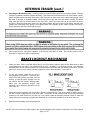
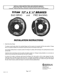
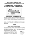
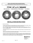
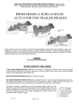
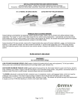
INSTALLATION INSTRUCTION AND SERVICE MANUAL Actuator/Trailer Dealer - Please provide these instructions to the consumer. Consumer - Read and follow these instructions. Keep them with the trailer for future reference. TITAN AERO 7500 ACTUATOR FOR TRAILER BRAKES INTRODUCTION TO SURGE BRAKING Surge braking is accomplished by replacing a trailer's standard tongue coupler with an actuator and adding hydraulic brake assemblies. The "surge" or "push" of the trailer toward the tow vehicle during deceleration automatically synchronizes these trailer brakes with the tow vehicle brakes. As the trailer pushes against the vehicle, the actuator telescopes together and applies force to its master cylinder, supplying hydraulic pressure to the trailer's brakes. Surge actuators of this type provide a service life of approximately five years with proper installation, usage, and maintenance. However, a well cared-for actuator can often exceed this estimate. To get the most benefit from your TITAN surge actuator, follow the instructions given in this manual and use common sense in caring for the TITAN AERO 7500 actuator and your entire trailer brake system. RATED CAPACITY AND USAGE 7,500 POUNDS MAXIMUM GROSS LOAD (weight of trailer fully loaded with all cargo and equipment). To find your trailer's Gross Load, use a commercial vehicle scale at a truck weigh station, grain elevator, etc. 700 POUNDS MAXIMUM TONGUE LOAD (weight applied downwards by the fully loaded trailer's coupler onto the tow vehicle's hitch). Measure your trailer's Tongue Load with the tongue in the horizontal towing position, using either a commercial scale or a bathroom scale if the load is small enough. Upwards tongue loads are not permissible. The AERO-7500 actuator is intended for use on recreational, marine, and agricultural occasional-use trailers, which are towed by passenger cars or pickups. Use ONLY with a two inch (2") diameter tow ball. The actual in-service rating is limited to that of the ball and hitch being used or the trailer manufacturer's G.V.W.R. shown on the certification label, whichever is lower. Page 1 of 13 #45030 05-07 INSTALLATION 1. The AERO 7500 Actuator is completely assembled and ready to bolt or weld into place onto straight three inch wide trailer tongues. Welding will make repair or replacement difficult but may be preferred. If the actuator must be painted for aesthetic reasons, then TITAN recommends painting ONLY the outer case and disassembling the unit prior to painting. Application of heavy coats of paint may interfere with component operation. If the actuator is welded on, then be sure to weld in a well ventilated area. Confirm the coupler and breakaway mechanisms work properly before operation. Store actuators indoors and in their original shipping carton until the time of installation. 2. Bolt the actuator to the tongue using 1/2 inch by 4 inch grade 5 bolts, nuts, and lock washers. The top two holes match standard coupler mounting holes on three inch wide trailer tongues, as shown in Figure 1. The third hole is recommended for all applications, but MUST be used for trailers with a Gross Load greater than 3500 pounds. Light weight tongues require spacer tubes inside for reinforcement such as a 3/4 inch outside diameter by eleven gauge piece of tubing. Using a torque wrench, tighten bolts to eighty (80) foot-pounds torque. 3. Since the AERO-7500 mounts flush to the top of the trailer tongue, the brake lines are best routed inside the trailer tongue and frame. One way to simplify attachment of the actuator is to turn several coils in the tubing at the actuator end. These coils can then be located inside the end of the tongue and will stretch the few inches necessary to allow the unit to be connected, and will spring back as the unit is bolted in place. A short length of flexible brake tubing is another option. DO NOT crush or kink the tubing as you mount the actuator. 4. Install the hydraulic brakes and brake lines on the trailer as described in the installation manual supplied with the brakes. TITAN recommends 3/16 inch brazed double wall tubing per S.A.E. J527 for use with all our actuator and brake products. Use forty-five degree (45°) double-flare tube ends per S.A.E. J533. DO NOT remove or modify the orifice connector <9> at the rear of your actuator's master cylinder. It connects directly to the brake tubing and ensures proper fluid flow characteristics. 5. After installation of the actuator, brake, and brake lines as described above, proceed immediately to the "BRAKE FLUID FILLING AND BLEEDING" instructions. * NOTE: <#> is the reference number shown in the assembly diagram of the actuator located at the end of this manual Page 2 of 13 INSTALLATION (cont.) Brake Fluid Filling and Bleeding 6. Fill the system with DOT 3-4 heavy-duty brake fluid. The braking system may be bled manually or with a vacuum or pressure type brake bleeding system. Both types of brake bleeding equipment should be available at your local automotive jobber. Follow manufacturer's instructions. 6a. After completing the “Installation” instructions, remove the master cylinder cap and fill the reservoir to threequarters full with DOT-3 brake fluid. DO NOT allow brake fluid to contact painted surfaces since it will damage the finish. Wipe up any spills immediately and wash the area with water. 6b. If you choose to manually bleed the system, an assistant makes the job easier. Please note the diagram in figure 2 (on the next page). Disconnect the trailer from the tow vehicle and hook the safety chains (NOT the actuator breakaway cable) together to form a loop. The loop should be centered below the actuator’s coupler as shown in Figure 2. 6c. Place a sturdy board such as a 2 x 4 into the safety chain loop below the coupler. The board should be four feet long or more so it will extend well above the actuator. Position the board to press against the front end of the actuator’s coupler and use it to force the coupler case into the actuator’s outer housing. This pumps the brake fluid into the trailer braking system. Manually pull the coupler case back to fully extended position and repeat the process. 6d. When the air bubbling stops inside the master cylinder, install a bleeder hose on the bleeder screw of the first wheel cylinder or disc brake caliper to be bled. Be sure to use the bleeder screw on top of the caliper. Start with the rear axle on tandem axle trailers. Submerge the other end of the hose in a glass container of brake fluid so that air bubbles can be observed. Open the bleeder screw one turn before pushing the coupler case in. When the coupler is pushed completely in, the bleeder screw should be closed to prevent air from being pulled back into the system. Air trapped in the brake lines will greatly reduce your braking efficiency. Repeat this process until no more bubbles are released with each stroke. Be sure to close the bleeder screw securely. 6e. Repeat the bleeding operation at each wheel cylinder or caliper. During the bleeding process, replenish the brake fluid so the level does not fall below half full level in the master cylinder reservoir. When bleeding is complete, fill the reservoir to within 3/8” of the top. Install the filler cap securely. * NOTE: <#> is the reference number shown in the assembly diagram of the actuator located at the end of this manual Page 3 of 13 TESTING TITAN SURGE BRAKE SYSTEMS Hydraulic surge actuator systems provide automatic and smooth trailer braking without special application by the tow vehicle driver. While this is extremely convenient it can sometimes be difficult to determine if the surge setup is functioning properly. The following steps provide a quick field-test to confirm that the trailer brake system is operational. 1. Move the trailer to flat, level ground, pulling FORWARD several feet before parking. This forward motion will ensure trailers equipped with free-backing brakes are in their normal operating mode. Disconnect the 'trailer from the tow vehicle and jack the trailer's tongue until it is horizontal. 2. Hook the trailer's safety chains (NOT the actuator's breakaway cable/chain) together to form a loop, which is centered below the actuator's coupler as shown in Figure 2. 3. Place a sturdy board, such as a 2 inch by 4 inch piece of lumber, into the chain loop below the coupler. The board should be 4 feet or longer so it will extend several feet above the actuator. Keep the end of the board a few inches off the ground, and position it to press against the front end of the actuator's coupler. 4. Stand in front of the trailer and face the rear. Apply force to the top end of the board to use it as a lever. Press back towards the rear of the trailer. The board will begin moving the coupler case (inner slide) into the actuator’s outer housing. 5. Keep pressing the top of the board to stroke the actuator and its internal master cylinder. If the trailer brake system is operational, the brakes will apply and keep the trailer from rolling away from you. Properly adjusted uniservo or duo-servo type brakes will prevent you from moving the trailer back more than a few inches. Freebacking type brakes will initially provide rolling resistance, but continued force on the board will switch them into free-backing mode, and you’ll be able to move the trailer backwards. 6. If you have uni-servo or duo-servo brakes, and stroking the actuator (as described previously) causes the trailer to roll away from you freely or with only minimal resistance, the brakes are NOT applying properly. If you have free-backing brakes, and stroking the actuator (as described previously) causes the trailer to roll away without initial resistance, the brakes are NOT applying properly. The brake system MUST be evaluated to determine the cause of the problem, and corrective action MUST be taken before the trailer is used. Use this procedure each time you tow your trailer to check your surge brake system operation. * NOTE: <#> is the reference number shown in the assembly diagram of the actuator located at the end of this manual Page 4 of 13 HITCHING TRAILER 1. Confirm the towing hitch and ball have a rating equal to or greater than the trailer G.V.W.R. and are properly. At and securely attached to the tow vehicle. The hitch MUST be installed so the trailer tongue is level (horizontal) when coupled to the tow vehicle. The AERO 7500 MUST be used ONLY with a 2” diameter tow ball. 2. To attach the coupler to the tow vehicle, lift the actuator handle fully, approximately thirty degrees (30°), to allow the ball latch to rotate to its open position. The handle will remain up to indicate that it is not yet attached to a ball. Lower the coupler onto the tow ball until the handle snaps to its closed position. Confirm that the ball is located and held securely in the coupler socket, and that the handle is fully down (horizontal). DO NOT force the handle to the closed position, otherwise damage may result. If the handle does not snap down, check that the ball is located fully in the coupler socket, and that the coupler components and spring move freely and are not damaged.. 3. Check that the actuator's coupler is securely latched onto the tow ball by extending the trailer's tongue jack to the ground. Use it to lift the trailer tongue and tow vehicle hitch two to four inches. The coupler and ball should... remain engaged. DO NOT tow the trailer unless the coupler is latched onto the ball securely. Retract the trailer I tongue jack before towing. 4. With the handle in the fully horizontal position, insert the quick release pin <43> through the back holes in the handle to further secure the coupler mechanism. 5. To uncouple the trailer, first block the wheels to keep the trailer from rolling. Lift the actuator handle fully to allow the ball latch to rotate. Lift the trailer tongue off the tow ball using a tongue jack if necessary. If your handle and jack are too far apart to operate at the same time, use your jack to raise the tongue just enough to put a SLIGHT upwards pull on the tow ball. Then lift the actuator handle and it will remain in the up position, allowing you to continue jacking your coupler off the ball. 6. As shown in Figure 3 (page 6), your tow vehicle’s hitch provides a safety chain hole or ring on each side. Consult your trailer manufacturer for proper safety chain recommendations. Attach your trailer’s safety chains securely to these connection points, being sure to cross the chains UNDER the trailer tongue. Safety chains MUST be used. This will prevent the trailer tongue from dropping to the road if the coupler separates from the tow vehicle’s hitch. If your tow vehicle’s hitch does not provide safety chain connection points, have appropriate ones added by a reputable hitch installer. * NOTE: <#> is the reference number shown in the assembly diagram of the actuator located at the end of this manual Page 5 of 13 HITCHING TRAILER (cont.) 7. Attach the actuator's break-away chain S-hook securely to one of the tow vehicle hitch's safety chain connection points (see Figure 3). Confirm that the trailer's safety chains are adjusted relative to the actuator's breakaway chain as noted above. DO NOT loop the breakaway chain around a bracket and hook it back onto itself. 8. Before towing, check that the break-away lever and cable are properly positioned as shown in Figure 4. The barrel stop on the break-away cable should be within 1/8 inch of the break-away lever. If the barrel stop is not visible or is located elsewhere, the actuator MUST be disassembled to determine the cause of the problem. Note that the break-away lever must be rotated fully to the rear with the break-away catch pin securely located under the break-away spring. The break-away catch pin will be in the lever's upper-most notch. 9. If the break-away lever and cable are not located correctly as described above, due to either the cable being pulled during use or by accident, it MUST be reset prior to the trailer being moved . * NOTE: <#> is the reference number shown in the assembly diagram of the actuator located at the end of this manual Page 6 of 13 HITCHING TRAILER (cont.) 10. Resetting the Breakaway Lever: Carefully loosen the brake line fitting going into the master cylinder. After the pressure is gradually released, retighten the fitting. Then remove the two bolts at the front of the master cylinder, which hold down the break-away catch spring <38>. With the two bolts removed, the break-away spring can be set aside. If the lever is ratcheted forward, use locking pliers to grip the lever and rotate it forward. The breakaway catch pin <39> can now be lifted from the outer case. Let the lever fully return to its rest position as shown in Figure 4. Place the break-away catch pin in the space between the lever's upper notch and the actuator case. Replace the break-away catch spring in its original position and retighten the two master cylinder bolts using a torque wrench to 108-132 inch-pounds of torque. 11. Sway control devices that restrict operation of the actuator CAN NOT be used. The actuator must be free to telescope in response to braking requirements. BRAKE LOCKOUT MECHANISM 1. When your Aero 7500 is used with disc brakes or non free backing brakes, there are two alternatives to allow normal backing of your trailer. Our solenoid back up valve < 4748800 > is a convenient choice. It is electrically activated when the tow vehicle is shifted into reverse and prevents brake fluid from flowing to the trailer. There is also a lock out lever which can be manually engaged to prevent brake activation. See Figure 5. 2. To use your lockout, check that no force is being applied to the actuator. To achieve this, position the towing vehicle and trailer on a flat surface, or with the trailer downhill from the tow vehicle. Set the vehicle's parking brake. Make sure the actuator's coupler case assembly <3> is pulled fully forward out of the outer case <2>. 3. Rotate the lockout assembly <40> (as shown in Figure 5) forward and up. Then push it back so that the hook on the lock out lever engages the top of the outer case. The actuator is now locked out and will not apply noticeable pressure to the trailer brakes as you back up. If you cannot rotate the assembly forward enough to reach the notch, make sure the actuator's coupler case assembly <3> is pulled fully forward out of the outer case <2>. 4. Back the trailer smoothly to the desired position. * NOTE: <#> is the reference number shown in the assembly diagram of the actuator located at the end of this manual Page 7 of 13 BRAKE LOCKOUT MECHANISM (cont.) 5. After backing, the brake lockout will automatically release and swing down the first time the trailer is pulled forward. The actuator is then again ready for normal forward trailering. MAINTENANCE 1. Before each towing, perform the following steps: - Check that the brake fluid reservoir is three-quarters full of DOT 3-4 brake fluid. Check for leaks and repair as required. - Examine the actuator for wear, bent parts, corroded/seized parts, or other damage. Have the affected components replaced with genuine TITAN service parts. Check to determine that the actuator mounting bolts (where applicable) are tightened to eighty (80) foot-pounds torque using a torque wrench. - Test the actuator and brake function as described in the “TESTING TITAN SURGE BRAKE SYSTEMS” section of this manual. Actuator travel over one inch indicates that the brakes need adjustment (or that the actuator has been structurally damaged). Actuator travel is the distance the coupler case assembly <2> moves relative to the outer case <1> during braking. Adjust the brakes following the instructions given in the brake installation manual. In general, back off adjusters ten clicks from locked drum rotation. Adjust freebacking brakes by rotating in the forward direction only. Failure to adjust brakes will result in loss of braking. 2. A film of grease on the hitch ball will extend coupler and ball life while eliminating squeaking. renew film each time trailer is used. Wipe clean and 3. Before towing, examine the actuator for bent parts or wear. Replace parts as necessary. Check to determine that mounting bolts are tight and welds not cracked. 4. There are no adjustments on the actuator. 5. Actuator travel (over one inch) shown by front roller path indicates a need to adjust the brakes. Adjust per instructions found in brake installation manual. In general, back-off adjusters 10 clicks from locked rotation. Adjust Free-Backing brakes by rotating in forward direction only. Failure to adjust may result in loss of braking. 6. Before storage or after extended use, TITAN recommends applying motor oil to the coupler components, lockout mechanism, and the three internal rollers to keep them moving freely and to prevent corrosion. * NOTE: <#> is the reference number shown in the assembly diagram of the actuator located at the end of this manual Page 8 of 13 AERO 7500 ASSEMBLY 1. Over time, you may need to disassemble your TITAN Aero 7500 for service or to replace components. Use the following steps to put the actuator back together, checking this manual's assembly diagram and parts list for reference. 2. Set the coupler case <2> on its left side so that its bottom is facing you. Set the ball catch casting <32> on its flat side with the spring pocket facing up. Place the ball latch torsion spring <33> in the pocket with the bent spring leg below the casting hole, and pointing up. Slide the casting and spring into the coupler behind the ball socket, lining up the holes. Check that the spring leg is located in the notch of the strut welded to the coupler. Push a 1/2 inch diameter damper pin <5> through the coupler case, spring, and casting. Check to see that the sub-assembly is operating properly by rotating the ball latch casting against the spring pressure. The casting should return to the closed position when released. 3. Set the coupler up-side down. Fix the small end of the damper <4> to the coupler case <3> with the 1/2" damper pin <5>. 4. Fit the lockout lever torsion spring <41> over the ball latch pin <5> on the right side, with the coupler case facing you. The long leg of the spring points to the center of the coupler case, and the short leg faces out. See Figure 6. Place the lockout lever <40> over the ball latch pin so that the short leg of the ball latch torsion spring <41> is hooked in the kidney shaped hole of the lockout lever. The lockout lever <40> should want to rotate down by both the force of gravity and the lockout torsion spring <41 >. Using your hands, hold the lockout lever <40> to the side of the coupler case assembly <3> and slide the assembly into the outer case. Lay the front roller <24> in the rear of the coupler case assembly <3> and allow it to roll forward into position. Locate the torsion handle spring <37> as shown in Figure 7, and temporarily lock it into position using the 1/4 inch diameter handle groove pin <35> (to avoid later inconvenience, do not neglect this step). Do not attach the retaining ring to the pin at this time. Insert a 1/2 inch diameter bolt <25> through the front hole in the outer case, through the coupler case assembly, and through the front roller. Secure the ½ inch bolt <25>, with a flat washer <27> and a ½ inch lock nut. 5. Rotate the actuator again so that it is laying up-side down. Place a block (roughly the size of a 2 inch by 4 inch section of lumber) under both ends of actuator to ease assembly. Slide the ½ inch bolt <25> through the second side hole from the front of the outer case, into the coupler case, and into one of the sintered iron rollers <23>. Note the beveled side of the rollers should face out towards the outer case sides. Position the roller separator <29> and slide the ½ inch bolt <25> though the holes of the separator. The separator needs to be positioned so the middle portion of the "U" is on the bottom, flush with the inner coupler. Continue sliding the ½ inch bolt <25> through the second rear roller, and finally through the outer case. Secure it with a ½ inch washer <27> and a ½ inch lock nut <26>. * NOTE: <#> is the reference number shown in the assembly diagram of the actuator located at the end of this manual Page 9 of 13 AERO 7500 ASSEMBLY (cont.) 6. The master cylinder <6> and pushrod assembly components <13> can now be assembled. Apply a light coat of brake fluid to the small opening of the rubber boot on the front of the master cylinder. This will ease assembly and reduce the chance of damaging the boot. The spring guide washer <18> can be identified by the attached 1/8 inch steel break-away cable and break-away lever. THIS PUSHROD ASSEMBLY SHOULD NEVER BE DISASSEMBLED OR ADJUSTED. Press the pushrod assembly into the rubber boot of the master cylinder. See the assembly diagram at the end of the manual. Place the plated master cylinder cover plate <7> in the actuator outer case with the four holes in alignment and the threaded flange for the filler cap up through the opening in the outer case. Lay the master cylinder gasket <8> over the cover plate. Pull the inner coupler <3> forward to full extension. Thread the break-away cable and lever through the outer case, from the inside-out. Lower the master cylinder and bracket into the outer case. The front of the pushrod assembly passes through the hole in the inner coupler. 7. Slip the 1/4 inch lock washers <12> over the 1/4 inch bolts <11>. With the assembly still upside down, lift the rear of the outer case slightly, and from the outside screw the bolts through the two rear-most master cylinder holes in the outer case. The 1/4 inch bolts will ensure the correct position of both the master cylinder cover and the gasket. 8. Rotate the damper <4> back down towards the rear of the actuator. Secure it with the last ½ inch bolt <25>, ½ inch washer <27> and a ½ inch lock nut <26>, by passing the bolt through the damper tube and outer case holes. 9. Turn the assembly over, right side up. Check that the master cylinder gasket is still correctly aligned to the forward two bolt holes. Place the break-away catch pin <39> in the space between the break-away lever's upper notch and the actuator case. Position the break-away catch spring <38> on top of the outer case over the bolt holes, with its tab pointing forwards. Make sure the spring's edges trap the break-away catch pin. Set the cable as described in the "HITCHING TRAILER" section of this manual. Secure the components with two 1/4 inch bolts and 1/4 inch lock washers. Tighten all four 1/4 inch master cylinder bolts to 108-132 inch-pounds torque, to ensure a positive master cylinder seal. 10. For the handle <31> assembly, place the handle torsion spring under the strut of the inner coupler. See Figure 7. Lower the handle into place being sure that the handle torsion spring legs are trapped above the permanently fixed pin in the handle. Rotate the ball latch casting forward by pulling it on the under side of the actuator. This will allow the handle to fall into its final position. Secure the handle with the 1/4 inch diameter groove pin and 1/4 inch retaining ring. Be sure that the pin passes through both handle spring loops. 11. Check the filler cap diaphragm and o-ring for damage. Screw the filler cap and gasket into the master cylinder cover. The filler cap only needs to be finger tight. 12. The actuator should now be fully assembled and ready for installation as described in this manual. * NOTE: <#> is the reference number shown in the assembly diagram of the actuator located at the end of this manual Page 10 of 13 AERO 7500 ACTUATOR PARTS DIAGRAM Page 11 of 13 AERO 7500 ACTUATOR PARTS LIST (Reference Parts Diagram on page 11) * * * * * * * Ref# 2 3 4 5 6A 6B 7 8 9A 9B 10 11 12 13 14 15 16 17 18 19 20 21 22 23 24 25 26 27 29 31 32 33 34 35 36 37 38 39 40 41 42 43 44 45 Part# 4500700 4518100183 4502000 4511400 2336100042 4714200042 4518200 4524400 1209800 4750300 4480701 4624200 0794000 4502700 2338400 2338500 2338600 1740600 4518300 4501300 1055500 4597100 4599500 4518400 4518500 2341300 4835400 4511200 4524900 4501100 4500900 4520000 4811500 4518600 4518700 4521500 4501400 4597200 4600100183 4600000 4745500 4706400 1502600 4748800 Description Outer Case, plated Coupler Case Assembly, plated Damper 1/2" Damper Pin/Ball Latch Pin Master Cylinder, drum brake Master Cylinder, disc brake Cover, Master Cylinder Gasket, Master Cylinder Orifice Connector, .015", drum brake Orifice Connector, .125", disc brake Filler cap with diaphragm Bolt, 1/4" x .875" 20 NC Lockwasher, 1/4" standard Pushrod & Breakaway Cable Assembly Push Rod Washer, push rod Spring Lock Nut, 5/16" - 18NC Spring Guide Breakaway Cable S - Hook Breakaway Lever Roll Pin, 3/16" x 1/2" Rear Roller, Sintered Iron Front Roller Bolt, 1/2" x 3 3/4" NF 1/2" - 20 NF Jam Nut Washer, 1/2" Roller Separator Handle Ball Latch, cast Spring, ball latch Bolt, 5/16" x 3" Grade 8 NC Groove Pin, 1/4" Retaining Ring, 1/4" Spring, handle Breakaway Catch Spring Breakaway Catch Pin Lockout Lever Lockout Torsion Spring Label, disc brake actuator Quick Release Pin & Lanyard Master Cylinder Repair Kit Solenoid Back Up Valve * designates --------Recommended Tools 7/16” wrench Snap Ring Pliers Torque Wrench Locking pliers Page 12 of 13 Qty 1 1 1 2 1 1 1 1 1 1 1 4 4 1 1 1 1 2 1 1 1 1 1 2 1 3 3 2 1 1 1 1 1 1 1 1 1 1 1 1 1 1 1 1 LIMITED WARRANTY Limited Warranty Titan Tire Corporation (TITAN) warrants its products to be free from defects in material and workmanship for one year from date of delivery to the original purchaser when properly installed, used and maintained by the purchaser. This warranty does not apply to damage or loss caused by any or all of the following circumstances or conditions: Freight damage. Parts, accessories, materials or components not obtained former approved in writing by TITAN. Misapplication, misuse and failure to follow the directions or observe cautions and warnings on installation, operation, application, inspection or maintenance specified in any TITAN quotations, acknowledgements, sales literature, specification sheet or installation instructions and service manual (“applicable literature”) If any TITAN products are found upon TITAN’S examination to have been defective when supplied, TITAN will either: credit the purchaser’s account for the purchase price of the TITAN product; or repair the product. TITAN has sole discretion in choosing which option to provide. For this LIMITED WARRANTY to apply, TITAN must receive notice of the alleged defect within 30 days of either the discovery of the alleged defect or the expiration of the warranty period, whichever is earlier. Any claim not made with in this period shall conclusively be deemed waived. If requested by TITAN, purchaser shall return the alleged defective product to TITAN for examination at Titan’s direction and expense. TITAN will not pay for expenses incurred in returning a product to TITAN without TITAN’S prior written authority. TITAN shall not be liable for any other expenses purchaser incurs to remedy any defect. Purchasers waive subrogation on all claims under any insurance. Limitation of Liability It is expressly agreed that the liability of TITAN is limited and TITAN does not function as an insurer. THE REMEDIES SET FORTH IN THIS WARRANTY SHALL CONSTITUTE THE EXCLUSIVE REMEDIES AVAILABLE TO THE PURCHASER OR USER AND ARE IN LIEU OF ALL OTHER REMEIDIES, EXPRESS OR IMPLIED. THE LIABILITY OF TITAN, WHETHER IN CONTRACT, IN TORT, UNDER ANY WARRANTY OR OTHERWISE, SHALL NOT EXCEED THE PURCHASE PRICE OF THE PARTICULAR PRODUCT MANUFACTURED, SOLD OR SUPPLIED BY TITAN. To Obtain Technical Assistance To enable TITAN to respond to a request for assistance or evaluation of customer or user operation difficulty, please provide at a minimum the following information by calling 1-800-872-2327 or within Iowa 1-515-265-9200: Model number, serial number and all other data on the specific component which appears to be involved in the difficulty. The date and from whom you purchased your TITAN product. State your difficulty, being sure to mention at least the following: Application, Nature of load involved, and Weight of the load. Field Service If field service at the request of the purchaser is rendered and the difficulty is found not to be with TITAN’S product, the purchaser shall pay the time and expense (at the prevailing rate at the time of service) of the seller’s field representative(s). Charges for service, labor and other expenses that have been incurred by the purchaser, its customer or agent without prior written authorization of TITAN will not be accepted. TITAN EXTENDS NO WARRANTY, EXPRESS OR IMPLIED, ON PRODUCTS NOT MANUFACTURED BY TITAN OR TO TITAN’S DESIGN SPECIFICATION, INCLUDING BUT NOT LIMITED TO SUCH ITEMS AS NON-TITAN TIRES, BRAKES, ACTUATORS, BEARINGS, HOSE AND TUBING, PURCHASER’S RECOURSE SHALL BE LIMITED TO ANY WARRANTY OF THE PERSPECTIVE MANUFACTURERS. THIS WARRANTY EXCLUDES ALL IMPLIED WARRANTIES OF MERCHANTABILITY OR FITNESS FOR A PARTICULAR PURPOSE OR ANY PURPOSE. THIS WARRANTY DOES NOT COVER NOR EXTEND TO INCIDENTAL OR CONSEQUENTIAL DAMAGE. Some states do not allow the exclusion or limitation of incidental or consequential damages, so the above limitation or exclusion may not apply to you. No representative has authority to make any representation, promise or agreement except as stated in this Limited Warranty. TITAN reserves the right to make design and other changes upon its products without any obligation to install the same on any previously sold or delivered products. THERE ARE NO WARRANTIES WHICH EXTEND BEYOND THOSE DESCRIBED ABOVE. EFFECTIVE JANUARY 1, 1998 THIS WARRANTY SUPERSEDES ALL PRIOR WARRRANTIES, WRITTEN OR IMPLIED. Page 13 of 13