1
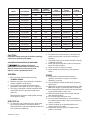
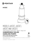
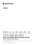
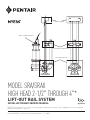
Top Rail Support Bail Assembly and Chain Intermediate Guide Bracket Lift-Out Rail System MODEL SRA/SRAX HIGH HEAD 2-1/2" THROUGH 4"* LIFT-OUT RAIL SYSTEM INSTALLATION AND SERVICE MANUAL FM Approved NOTE! To the installer: Please make sure you provide this manual to the owner of the equipment or to the responsible party who maintains the system. Part # 23833A546 | © 2012 Pentair Pump Group, Inc. | 11/08/12 Model Part Number Pump Discharge System Discharge SRA23HH-LE 25135F053 N/A N/A 25068D001 25069D012 N/A SRA23HH 25135F052 2.5 3 25068D001 25069D012 23497A103 SRA33HH-LE 25135F031 N/A N/A 25068D003 25069D015 N/A SRA33HH 25135F030 3 3 25068D003 25069D015 23497A103 SRA44HH-LE 25135F074 N/A N/A 25068D002 25069D014 N/A SRA44HH 25135F070 4 4 25068D002 25069D014 23497A101 SRA46HH 25135F072 4 6 25068D002 25069D014 25046A101 SRAX23HH-LE 25135F063 N/A N/A 25068D001 25069D013 N/A SRAX23HH 25135F062 2.5 3 25068D001 25069D013 23497A103 SRAX33HH-LE 25135F079 N/A N/A 25068D003 25069D017 N/A SRAX33HH 25135F078 3 3 25068D003 25069D017 23497A103 SRAX44HH-LE 25135F077 N/A N/A 25068D002 25069D016 N/A SRAX44HH 25135F075 4 4 25068D002 25069D016 23497A101 SRAX46HH 25135F076 4 6 25068D002 25069D016 25046A101 SRAX48HH 25135F082 4 8 Elbow Size CAUTION! CALIFORNIA PROPOSITION 65 WARNING: This product and related accessories contain chemicals known to the State of California to cause cancer, birth defects or other reproductive harm. GENERAL PUMPS 11. Pump builds up heat and pressure during operation, allow time for pump to cool before handling or servicing. 12. Only qualified personnel should install, operate or repair pump. 13.Keep clear of suction and discharge openings. DO NOT insert fingers in pump with power connected. 14.Do not pump hazardous material not recommended for pump (flammable, caustic, etc.). 15.Make sure lifting handles are securely fastened each time before lifting. 16.Do not lift pump by the power cord. 17.Do not exceed manufacturer’s recommendation for maximum performance, as this could cause the motor to overheat. 18.Secure the pump in its operating position so it cannot tip over, fall or slide. 19.Keep hands and feet away from impeller when power is connected. 1. Most accidents can be avoided by using COMMON SENSE. 2. Read the operation and maintenance instruction manual supplied with the pump. 3. Do not wear loose clothing that can become entangled in the impeller or other moving parts. 4. This pump is designed to handle materials which could cause illness or disease through direct exposure. Wear adequate protective clothing when working on the pump or piping. ELECTRICAL 5. To reduce the risk of electrical shock, pump must be properly grounded in accordance with the National Electric Code and all applicable state and local codes and ordinances. 23833A546 11/08/12 RTF 6. To reduce risk of electrical shock, disconnect the pump from the power source before handling or servicing. 7. Any wiring to be done on pumps should be done by a qualified electrician. 8. Never operate a pump with a power cord that has frayed or brittle insulation. 9. Never let cords or plugs lay in water. 10. Never handle connected power cords with wet hands. Read these safety warnings first before installing, servicing, or operating any pump. Base Flange Elbow Part Number Part Number Part Number 2 20.Submersible grinder pumps are not approved for use in swimming pools, recreational water installations, decorative fountains or any installation where human contact with the pumped fluid is common. 21.Do not operate pump without safety devices in place. 22.For hazardous locations, use pumps that are listed and classified for such locations. IMPORTANT! F. E. Myers is not responsible for losses, injury or death resulting from a failure to observe these safety precautions, misuse or abuse of pumps or equipment. GENERAL INFORMATION: General Construction: The base and pump guide plate on all the models are made of ASTM A536 ductile iron (see Fig. 1). The mounting flange on all of the models is made of ASTM A48 Class 30 cast iron. The locating pins and all fasteners are made of 300 series stainless steel. Gaskets are constructed of neoprene rubber material. The elbows are constructed of ASTM A48 Class 125 cast iron. The hazardous location/nonsparking models have 260 yellow brass sleeved onto the locating pins and have a cast brass mounting plate to meet the non-sparking requirements. Lift-Out Chain: Myers offers lift-out chain packages for each pump we manufacture. Packages vary depending on the pump design and requirements. Each lift-out chain package is designed to mount to the top of the pump and allow the pump to be safely hoisted up the guide rail. Rail Support Brackets: The SRA lift-outs are designed to use 2" standard pipe for guide rails. A top rail support bracket is available to be mounted to the hatch frame. Intermediate brackets are available for deep basins. It is recommended that if the rail length is over 21' that an intermediate bracket be installed. After every additional 20' of rail, another intermediate bracket should be used for proper rail support. Basin Covers: Myers has several types of basin covers available for use with either fiberglass or concrete basins. Basin hatch type covers are available in either steel or aluminum construction. The basin cover frame is designed to allow for mounting of rail support brackets. Basin Bottom: All cement pipe basins must have a smooth level troweled bottom for level mounting of discharge casting. Junction Boxes: If a junction box is used in a hazardous location, it must be a hazardous location approved type with hazardous location cord connectors. Wires from the junction box must pass through a hazardous location seal connector. Level Sensing Controls: Intrinsically safe type float controls are recommended for all applications and required for hazardous location/non-sparking service. An intrinsically safe control panel relay will limit the current and voltage to the level controls. A Myers control panel can be supplied with this type circuitry. The float level controls maintain the basin sewage water level by controlling pump turn-on and turn-off levels. 1. The lower turn-off control should be set so that the pump stops at approximately the top of the pump. Consult the factory for any settings below this point. 2. The upper turn-on control should be set above the lower turn-off control. The exact height between the two controls is determined by the number of pump starts desired and the depth of basin. A maximum of 10 starts per hour should not be exceeded. 3. The override control is set at a specified height above the upper turn-on control. 4. The alarm control is set about 6" – 12" above the override control. 5. No control should be set above the inlet invert. Valves: It is recommended that all check valves and shut-off valves be mounted outside the sump in a valve box. (See typical drawing detail, Fig. 1.) Shut-off valves should be of the water works approved type with resilient rubber disk seat. CAUTION: After the pump is installed and sewage has entered the basin there is danger. Sewage water gives off methane and hydrogen sulfide gases, which are poisonous. Never enter a wetwell unless proper confined space entry procedures are followed. INSTALLING RAIL SYSTEM PARTS (Fig. 3) Mounting Cover, Discharge Base and Rails 1. Set concrete cover with hatch opening in position. 2. Bolt top rail support plates (Fig. 6) to hatch frame. The plate has slots so the two plates in a duplex system can be adjusted to obtain required centerto-center distance between pumps. 3. Lower the base or base/elbow assembly into the basin. 4. Position the base elbow assembly by dropping a plumb line from center of pipe supports, located on top rail support plate, to center of tapered pins protruding from the top of the base elbow assembly. Level the elbow flange in two directions, 3 23833A546 11/08/12 90° to each other. Shims may be required under the base in order to obtain this level condition. Mark the position of the base hold down bolts through the holes in the base. 5. Move the base aside to allow drilling of the concrete for 3/4" expansion bolts, 2-1/2" long. Move the base over the bolt holes and recheck with level and plumb line. Install expansion bolts. 6. Cut the pipe guide rails to the proper length and install them between the pipe supports at the top of the basin and pins on the base. Guide rails are Schedule 40, galvanized or stainless steel. 7. Install discharge pipe as required by the particular job specifications. 5. Re-check rails; they must be straight and plumb. Move intermediate guide bracket if necessary to perfectly align rails. After alignment is secured, tighten nuts on U-bolt. 6. If a second intermediate guide bracket is used, the above procedure is followed for installation. Attaching Mounting Plate to Pump 1. Attach the mounting plate with the supplied bolts. (See Parts List, page 5.) The mounting plate should be turned so that the two locating pins are horizontal when attached to the pump discharge. 2. Mount the guide plate to the mounting plate using the two set screws provided. IMPORTANT: DISCHARGE PIPE AND GUIDE RAILS MUST BE PARALLEL IF INTERMEDIATE GUIDE BRACKET IS USED. Installing Pump and Mounting Plate 1. Attach the lifting chain to the pump. This is done by installing two eye bolts, or by installing the lifting bail (Fig. 4) provided with the lifting chain package. 8. If the top rail support plate cannot be attached to the hatch cover frame, a special rail bracket (Fig. 7) can be furnished for mounting directly to a pipe cemented in the basin wall. This bracket is set and aligned with discharge base the same as described for the rail guide plate attached to the frame. INSTALLING INTERMEDIATE GUIDE BRACKET (Fig. 5) Guide Rail Length IGB Required 21' or less 0 21' – 40' 1 Over 40' 2 2. A hook is located on the top rail support (Fig. 3) to hold the upper end of the chain when not in use. 3. Position pump so the guide rails are located in the slots of the guide plate. Slowly lower the pump down the guide rails to the base. The locating pins (horizontal pins on mounting plate) should come to seat in the inclined surface of the arms. 1. Remove guide rails (Fig. 3), and cut a piece from each one. These pipes must be exactly the same length and of a length that will permit installing the intermediate guide bracket in the desired location. 2. Place the cut pieces of pipe over the guide rail pins located in the base. 3. Set the intermediate guide bracket in position with tapered guides into pipes. Put U-bolt around discharge pipe and tighten lightly. 4. Measure from joint on tapered plug on intermediate guide bracket to joint of tapered plug on top rail support and cut two rails to this length. Put rails in place and tighten screws in top rail support. Holes are slotted to adjust for any error in rail pipe length. 23833A546 11/08/12 WARNING! Do not exceed working load limit of chains and other lifting devices. Do not use chains or lifting devices where failure could result in loss of life. Examine chains and lifting devices for deformation or damage before and after each lift. CAUTION: No persons should be in the sump basin when pump is lowered into position! Air Venting: Air tends to trap in the pump volute when water raises in the sump or when the pump is lowered into water after service. To vent off this air, a small hole is drilled into the pump volute. Be sure this vent hole is clean after any service work on pump. Air venting is not a problem after initial start. 4 SRA/SRAX HIGH HEAD LIFT-OUT RAIL SYSTEM PARTS LIST 9A Fig. 1 Ref No. Description No. SRA/ Req’d SRAX23HH-LE 25068D001 SRA/ SRAX23HH SRA/ SRAX33HH-LE SRA/ SRAX33HH 25068D001 25068D003 25068D003 1 Base L/O; CI Head Grinder 1 2 Plate; Mounting 1 3 Pin, Locating 2 4 Pin, Plate, Guide to Plate, Mounting 1 5 Plate, Guide 1 7 Stud 4 05659A103 05659A103 25069D012-standard 25069D013-hazardous SRA/ SRAX34HH SRA/ SRAX44HH-LE SRA/ SRAX44HH SRA/ SRAX46HH 25068D002 25068D002 25068D002 25069D015-standard 25069D017-hazardous 25069D014-standard 25069D016-hazardous 25073A002-standard 25074A000-hazardous 25073A001 25073A001 25073A001 SRA/ SRAX48HH 25073A002-standard 25074A000-hazardous 25073A001 25072C000-standard 25072C001-hazardous 25073A001 25073A001 25073A001 25072C000-standard 25072C001-hazardous RTF RTF 05659A103 05659A103 05659A103* 05659A103* 05659A103* 05231A081 05231A081 05863A019 05863A019 05863A019 9 Gasket, Elbow Side 1 05231A081 05231A081 9A Gasket, Pump Side 1 05231A077 05231A077 10 Elbow, Pipe Flanged 1 - 23497A103 - 23497A103 - 23497A101 25046A101 11 Nut, Hex 4 19109A082 19109A082 19109A082 19109A082 19109A082* 19109A082* 19109A082* 12 Screw, Cap Hex 4 19105A033 19105A033 19105A033 19105A033 19105A038* 19105A038* 19105A038* 13 Screw, Set Hdls Hex 2 06024A010 06024A010 06024A010 06024A010 06024A010 06024A010 06024A010 * (double the No. Required) 5 23833A546 11/08/12 TYPICAL INSTALLATION FOR DUPLEX Discharge Pipe and Outside Valve Pit Concrete Basin - All Pump Types Pipe Elbow Float Mtg. Bracket Pipe Tee Service Pole Option Check Valve Gate Valve Flashing Alarm Light Weatherproof Control Box Power Supply Conduit Cord Seal Connectors for Power and Control Cords (not shown) Hinged Access Door Alum. or Steel Top Rail Support (bolts to cover frame) Outside Valve Pit Lifting Chain Gate Valve Opt. Junction Box Must be used if control box is offset from basin Inlet Pipe (size as req’d) Below Frost Level Check Valve Discharge Piping - can be galv. steel or ductile iron 2" Pipe Guide Rails must be plumb Discharge/Rail Support Casting Bottom of basin must have smooth troweled surface for mtg. support casting Fig. 2 23833A546 11/08/12 6 NOTE: Metric Dimensions in [mm] INSTALLATION FOR RAIL SYSTEM 115/8 [295] 111/2 [292] 53/4 [146] 10 [254] 10 [254] Plate Mounting 5 [127] 9 7 /8 [22] 91/2 [241] 45/8 [117] Cover Frame Top Rail Support Fig. 6 Guide Rails (by others) 2" Pipe Sch. 40 Chain Assembly Fig. 4 Intermediate Guide Bracket (as req’d) Fig. 5 14 /8 [359] 1 Discharge Pipe (by others) A 5 Plate, Guide Pin, Guide 6 Screw, Set 7 8 Disch. B 81/2 [216] Pin, Locating 2 Screw, Cap 3 Elbow Bottom of basin must have smooth troweled surface Base 1 Elbow Size 2.5 x 3 3x3 4x4 6x4 * Standard parts are cast iron. Hazardous location parts are non-sparking brass. 4 Gasket 111/2 [292] 4A Gasket “A” 7 (178) 7 (178) 8 (203) 9-1/2 (241) Bolt to basin bottom with 3/4" expansion bolt - 21/2" long min. “B” 14 (356) 14 (356) 15 (381) 16-1/2 (419) Fig. 3 7 23833A546 11/08/12 BAIL ASSEMBLY AND CHAIN Pumps WHV Pumps and 3, 5, 7-1/2 HP Grinders R and V Pumps 1 2 3RH, 3V and WG/WGH Pumps WG75HH, WG100H and WG150H Pumps 3MW Pumps Chain Package CP-5 CP-5SST CP-10 CP-10SST CP-15 CP-15SST CP-20 CP-20SST CP-75-3 CP-75SST-3 Package Part No. 25193A050 25193A051 25193A010 25193A011 25193A015 25193A016 25193A020 25193A021 25193A110 25193A111 1 2 Ring Part Bail Lift Part No. No. 23532A001 23531A002* 23532A002 23532A001 25371B000 23532A002 23532A001 25371B004 23532A002 23532A001 25371B001 23532A002 23532A001 07599726200* 23532A002 *Note: Uses a separate piece of chain to substitute for the bail lift. Fig. 4 INTERMEDIATE GUIDE BRACKET U-Bolt IGB-2-3 IGB-2-4 IGB-2-6 Fig. 5 23833A546 11/08/12 8 Part No. 24966D009 24966D010 24966D011 TOP RAIL SUPPORT Fig. 6 Fig. 7 9 23833A546 11/08/12 TYPICAL DIMENSIONS FOR BASIN HATCH WHEN MOUNTING IN CONCRETE Duplex D17 D14 D19 D22 D30 D31 D21 Basin Dia. D30 Fig. 8 D24 Duplex Pumps WG30/WG50 WG30H/WG50H/WG75H WG75HH/WG100H/WG150H 3V/3VX 3RH/3RHX Basin Dia. Pump System Discharge Discharge 60 2.5 60 3 4RH/4RHX 4RH/4RHX-M2 60 4 4VH/4VHX 4VHS_4VHSX-1PH 4VHS_4VHSX-3PH 4RC/4RCX-M2 60 4 4R/4RX 4V/4VX 60 4 4VHA/4VHAX 4RC/4RCX 4VC/4VCX 72 4 4VE/4VEX 4VL/4VLX 72 4 23833A546 11/08/12 D19 D21 D22 D14 D17 D24 D30 D31 3 24 42 14 10 11.5 7 11 6 3 4 4 6 8 4 6 24 24 28 28 RTF 30 30 42 42 48 48 RTF 48 48 14 14 12 12 RTF 12 12 10 10 10 10 RTF 10 10 11.5 11.5 11.5 11.5 RTF 11.5 11.5 7 7 1.63 1.63 RTF 1.63 1.63 11 13 13 16 RTF 13 16 6 8 8 11 RTF 8 11 8 RTF RTF RTF RTF RTF RTF RTF RTF 4 6 8 4 6 8 4 6 8 28 28 RTF 36 36 RTF 36 36 RTF 48 48 RTF 48 48 RTF 54 54 RTF 12 12 RTF 18 18 RTF 18 18 RTF 10 10 RTF 10 10 RTF 10 10 RTF 11.5 11.5 RTF 11.5 11.5 RTF 11.5 11.5 RTF 5.69 5.69 RTF 7.63 7.63 RTF 7.63 7.63 RTF 13 16 RTF 13 16 RTF 13 16 RTF 8 11 RTF 8 11 RTF 8 11 RTF 10 TYPICAL DIMENSIONS FOR BASIN HATCH WHEN MOUNTING IN CONCRETE Simplex D19 D22 D17 D14 Basin Dia. D21 D24 Fig. 8 Simplex Basin Dia. D4/Pump Disc. System Discharge D19 D21 D22 D14 D17 D24 D30 D31 48 2.5 3 24 18 14 10 11.5 7 - - 48 3 4RH/4RHX 4RH/4RHX-M2 48 4 4VH/4VHX 4VHS_4VHSX-1PH 4VHS_4VHSX-3PH 4RC/4RCX-M2 3 4 4 6 8 4 24 24 28 28 RTF 30 18 18 24 24 RTF 24 14 14 10 10 RTF 10 10 10 10 10 RTF 10 11.5 11.5 11.5 11.5 RTF 11.5 7 7 0.38 0.38 RTF 0.38 - - 48 4 6 30 24 10 10 11.5 0.38 - - 4R/4RX 4V/4VX 48 4 4VHA/4VHAX 4RC/4RCX 4VC/4VCX 4VE/4VEX 60 4 8 4 6 8 4 6 RTF 28 28 RTF 36 36 RTF 20 20 RTF 24 24 RTF 12 12 RTF 15 15 RTF 10 10 RTF 10 10 RTF 11.5 11.5 RTF 11.5 11.5 RTF 5.69 5.69 RTF 4.63 4.63 - - 8 RTF RTF RTF RTF RTF RTF - - 4VL/4VLX 60 4 6 8 36 36 RTF 26 26 RTF 15 15 RTF 10 10 RTF 11.5 11.5 RTF 4.63 4.63 RTF - - Pumps WG30/WG50 WG30H/WG50H/WG75H WG75HH/WG100H/WG150H 3V/3VX 3RH/3RHX 4 Fig. 9 Valve Box Dia. 48 48 D 11 13 Valve Box Dimensions 90˚ Elbow Tee Valve Size (2 Req’d) (1 Req’d) 3 3x3 3x3x3 3 4x3 4x4x4 A&B Hatch 24 x 30 24 x 36 C Hatch Offset 15 16 11 23833A546 11/08/12 STANDARD LIMITED WARRANTY Pentair Myers® warrants its products against defects in material and workmanship for a period of 12 months from the date of shipment from Pentair Myers or 18 months from the manufacturing date, whichever occurs first – provided that such products are used in compliance with the requirements of the Pentair Myers catalog and technical manuals for use in pumping raw sewage, municipal wastewater or similar, abrasive-free, noncorrosive liquids. During the warranty period and subject to the conditions set forth, Pentair Myers, at its discretion, will repair or replace to the original user, the parts that prove defective in materials and workmanship. Pentair Myers reserves the right to change or improve its products or any portions thereof without being obligated to provide such a change or improvement for prior sold and/or shipped units. Start-up reports and electrical schematics may be required to support warranty claims. Submit at the time of startup through the Pentair Myers website: http://forms.pentairliterature.com/startupform/startupform.asp?type=m. Warranty is effective only if Pentair Myers authorized control panels are used. All seal fail and heat sensing devices must be hooked up, functional and monitored or this warranty will be void. Pentair Myers will cover only the lower seal and labor thereof for all dual seal pumps. Under no circumstance will Pentair Myers be responsible for the cost of field labor, travel expenses, rented equipment, removal/reinstallation costs or freight expenses to and from the factory or an authorized Pentair Myers service facility. This limited warranty will not apply: (a) to defects or malfunctions resulting from failure to properly install, operate or maintain the unit in accordance with the printed instructions provided; (b) to failures resulting from abuse, accident or negligence; (c) to normal maintenance services and parts used in connection with such service; (d) to units that are not installed in accordance with applicable local codes, ordinances and good trade practices; (e) if the unit is moved from its original installation location; (f) if unit is used for purposes other than for what it is designed and manufactured; (g) to any unit that has been repaired or altered by anyone other than Pentair Myers or an authorized Pentair Myers service provider; (h) to any unit that has been repaired using non factory specified/OEM parts. Warranty Exclusions: Pentair MYERS MAKES NO EXPRESS OR IMPLIED WARRANTIES THAT EXTEND BEYOND THE DESCRIPTION ON THE FACE HEREOF. Pentair MYERS SPECIFICALLY DISCLAIMS THE IMPLIED WARRANTIES OF MERCHANTABILITY AND FITNESS FOR ANY PARTICULAR PURPOSE. Liability Limitation: IN NO EVENT SHALL Pentair MYERS BE LIABLE OR RESPONSIBLE FOR CONSEQUENTIAL, INCIDENTAL OR SPECIAL DAMAGES RESULTING FROM OR RELATED IN ANY MANNER TO ANY Pentair MYERS PRODUCT OR PARTS THEREOF. PERSONAL INJURY AND/OR PROPERTY DAMAGE MAY RESULT FROM IMPROPER INSTALLATION. Pentair MYERS DISCLAIMS ALL LIABILITY, INCLUDING LIABILITY UNDER THIS WARRANTY, FOR IMPROPER INSTALLATION. Pentair MYERS RECOMMENDS INSTALLATION BY PROFESSIONALS. Some states do not permit some or all of the above warranty limitations or the exclusion or limitation of incidental or consequential damages and therefore such limitations may not apply to you. No warranties or representations at any time made by any representatives of Pentair Myers shall vary or expand the provision hereof. 1101 MYERS PARKWAY 490 Pinebush Road, Unit #4 ASHLAND, OHIO, USA 44805 CAMBRIDGE, ONTARIO, CANADA N1T 0A5 419-289-1144800-363-PUMP WWW.FEMYERS.COM Warranty Rev. 12/13