1
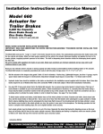
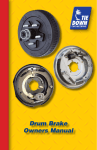
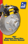
Eliminator Vented
Disc Brake
Owners Manual
Eliminator Vented Disc Brakes Exclusive Features
“Whenever possible, the tendency is to use an aluminum alloy in order to reduce
weight. These alloys are much lighter and are also much better heat conductors:
220W/m.˚K for aluminum compared to 44 W/m.˚K for cast iron”. That’s 5X faster!
*Haynes Automotive Disc Brake Manual
Bi-metal Piston
Bi-metal piston combines a stainless steel outer jacket with an anodized aluminum
inner sleeve to shed braking heat 5X faster than one piece stainless pistons. The
stainless steel outer jacket is specifically designed for road salt and salt water
conditions. U.S. Patent #7,028,813
Oversized Rubber Boot
Rubber boot is 50% thicker by design and provides for positive piston withdrawal.
Stainless Steel Bleeder Valves
Type 304 stainless steel with teflon coating for easy bleeding.
Stainless Steel Slider Pins
Stainless steel provides corrosion resistance for smoother brake operation. The hex
head design allows fast removal for easy servicing.
Vented Rotor
Eliminator rotors are vented to provide faster cooling and are available in E-coat,
GalvX coatings and Stainless Steel.
Aluminum Caliper
Aluminum sheds heat 5X faster than traditional cast iron, resulting in cooler braking
even in the worst conditions. E-coat finish protects the caliper from salt buildup in
harsh environments.
Lifetime Ceramic/Stainless Steel Brake Pads
No Dust, No Rust. Lifetime Warranty Automotive quality ceramic brake pads with
stainless steel backing plates.
Slim Design
Slim caliper design allows for short axle overhangs and aids in faster cooling.
Bronze Bushing
Oil impregnated bronze bushings last longer, slide smoother and will NOT corrode.
Vented Rotor Disc Brakes, w/Aluminum Caliper
Read your trailer manufacturer’s operating manual and follow the towing vehicle’s
guidelines for towing capability, hitch requirements and other towing information.
Congratulations on your decision to have Tie Down Engineering vented rotor disc brakes
with aluminum caliper installed on your trailer. Disc brakes have many advantages over
drum brakes. These include:
• Greater fade resistance
• Self cleaning
• Self adjusting
• Less maintenance
• Greater stopping power
• Easy visual inspection without removing any parts
Tie Down Engineering vented rotor disc brakes with aluminum calipers have many exclusive features not found on automotive type brakes modified for trailer use. Please
see our web site at tiedown.com for further information on features and benefits.
Vented rotor disc brakes are designed to activate when the vehicle’s brakes are
applied. As the vehicle stops or slows, the momentum of the trailer pushes forward
developing pressure in the actuator (master cylinder), used to apply pressure to the
brakes.
Operating Information
Read and understand the towing information for your trailer and actuator.
Check your trailer frequently for any leaks in the hydraulic system, which includes the
actuator, brake lines and brakes.
The brake rotors are made of steel and will show surface rust on the braking surface
when not used for a week or more. Normal use will wipe the rust off of the rotor surface. If the trailer is used in salt water, it is recommended that you rinse off the brakes
with fresh water after each use to reduce the effects of saltwater corrosion.
Your trailer should tow easily. Disc brakes operate at a higher temperature than drum
brakes. This is normal and is very similar to the way disc brakes operate on your vehicle. If for any reason your trailer does not tow easily or wants to veer to one side, stop
and investigate immediately and solve the problem.
Towing a trailer (even a trailer with brakes) puts an added load on the tow vehicle’s
handling and braking capabilities. Do not follow to closely; you will need extra distance
to maneuver and to stop.
Towing downhill puts added stress on both the tow vehicle and the trailer. Slow down
before you start on an incline and maintain a controlled downhill speed with repeated
application of brakes followed by a cooling period when brakes are not applied. It is
very important to start off with a slow speed and maintain it rather than trying to slow
down from a higher speed. Should you feel the brakes on the trailer or tow vehicle are
running hot or showing signs of fade, stop immediately on the side of the road and
allow the brakes to cool before resuming your trip.
2
Vented Rotor Disc Brakes, w/Aluminum Caliper
Should you feel the tow vehicle and trailer brakes are not working as they should;
have the tow vehicle and trailer inspected. Make sure your trailer’s GVW is within the
tow vehicles capacity. If your trailer has multiple axles, verify that the GVW of the trailer
does not exceed the capacity of the brakes, which is 3750 lbs on 10-inch (5 lug) brakes
and 6000 lbs on 12-inch (6 lug) brakes, per axle. Some states require brakes on all axles.
Check with your state laws and the state laws of where you will be using your trailer.
After long trips or downhill towing, your brakes could be very hot and it is a good idea
to let them cool down before submerging in cold water. The change in temperature of
very hot brakes submerged in water creates additional stress on the parts and could
cause damage to your brakes.
Pads must be replaced when the friction material is 3/32” or less. Original Tie Down
Engineering brake pads have a GalvX coated backing plate that aids in corrosion resistance. Replacement pads can also be purchased at most auto parts stores. Use NAPA
#TS-7192-M or IBN # 289 and MXD289 (1990 Chevrolet Cavalier front brakes).
Use DOT 3 brake fluid only. DO NOT USE SILICONE BASED BRAKE FLUID.
When backing a trailer with disc brakes, you must have a lockout lever or preferably
an electrically operated solenoid to stop brake pressure to the disc brakes. The solenoid
is mounted at the rear of the actuator, between the master cylinder and brake line. It
has a wire connected to your back up lights to stop or redirect the fluid to keep the
brakes form operating.
Replace Brake Pads
1. Elevate the trailer using the manufacturers instructions. Always use jack stands for support. Do not depend on a jack to support the trailer. Block wheels to keep trailer from rolling.
2. Remove the tire/wheel assembly. Inspect the rotor surface. Check for excessive wear or grooves that may affect braking. Original “Cap Style” rotor thickness is .939” with a minimum thickness of .85” or 21.6 mm. Original “Integral” rotor thickness is .75” with a minimum thickness of .67” or 17 mm.
3. Inspect brake pads. Minimum thickness is 3/32”. Pads should be replaced if below this width.
4. Remove the caliper by unscrewing the slider pins from the mounting bracket. Be careful to hold the caliper in place so that it does not fall and pull on the brake hose. The inside pad is spring loaded in the caliper piston. Pry this pad out gently with a flat blade screwdriver. The outside pad is held in place with two metal tabs. Use a large pair of pliers to straighten the tabs to remove the outside pad.
5. Clean the rotor with a brake cleaning spray. Replace brake pads in reverse order. The tabs should only be bent enough to hold the pad in place. Do not bend tab to far or the pad will not seat correctly. Outside pad should be able to “wiggle” after tab is bent.
6. Clean threads oN slider bolts and mounting plate and apply a coating of Loctite
or similar brand of thread lock. Tighten bolts to 40 ft lbs. DO NOT REASSEMBLE WITHOUT APPLYING LOCTITE® TO THE SLIDER PIN THREADS AND THE BACKING PLATE. SLIDER PINS COULD BACK OUT AND CAUSE PERMANENT DAMAGE TO YOUR BRAKES AND TRAILER.
Removing Hub/Rotor
Bleeder Valve
1. If your axle has an integral Vented
style rotor, hub and rotor is Slider Pin
Caliper
one piece, and will come off as one.
Brake Line Out
2. If you have a cap style rotor, Mounting
the rotor will be removed Plate
after the wheel and caliper is removed. The hub will come off separate.
Spindle/Alxe
3. Elevate the trailer using the manufacturers instructions. Always use jack for support. Nut/Bolt
Do not depend on a jack to Brake
support the trailer. Block Flange
wheels to keep trailer from rolling.
Intergal Style Rotor
4. Remove the tire/wheel assembly.
5. Remove the caliper by unscrewing the slider pins from the mounting bracket. Be careful to hold the caliper in place so that it does not fall and pull on the brake hose. Support the caliper so that it does not “hang” from the brake line.
6. Remove the grease cap from the hub by prying around the edge of the cap.
7. Bend the locking tang washer to the “free” position. If spindle is equipped with a
cotter key, straighten cotter key to remove.
8. Remove the spindle nut in a counter clockwise direction and remove the
spindle washer.
9. Remove the hub from the spindle. Be careful not to allow bearings to fall out
of the hub.
10. Clean bearing and cup surfaces, repack with lithium marine grade grease.
11. Place hub on spindle in reverse order as listed above. Rotate the hub while
tightening the spindle nut to approximately 50 ft lbs. This translates into full hand pressure with a 12” long set of pliers or 12” long wrench.
12. Loosen the spindle nut to remove the torque, do not rotate hub.
13. Finger tighten the spindle nut until snug, backing out only to line up the locking tang washer.
14. Bend the locking tang tab in place.
15. Replace rotor. Clean threads of slider bolts & mounting bracket and apply a
fresh coating of Loctite® to the pins as well as the mounting bracket. Tighten pins to 40 ft lbs. DO NOT REASSEMBLE WITHOUT APPLYING LOCTITE® TO THE SLIDER PIN THREADS AND THE BACKING PLATE. SLIDER PINS COULD BACK OUT AND CAUSE PERMANENT DAMAGE TO YOUR BRAKES AND TRAILER.
16. Replace cap. Install tire/wheel assembly, tighten wheel nuts to Trailer
manufacturer specifications. Test wheel for excessive tightness or excessive play. readjust in necessary.
17. Road test vehicle in a safe place before traveling on main roads in traffic.
4
Installation/Replacement Instructions for
Vented Disc Brakes
1.
On a bare axle attach mounting plate to the brake flanges on the axle. Preferred position is at “12:00” high or to the back side. Exact positioning will be determined by the brake flange. Use 7/16” x 1-1/4” zinc hex bolts, lock nuts/washers and torque to 40 lbs. Note: brake mounting plates can have 2 or 4 holes for attaching to the axle.
2. If installation is on a completed trailer, remove tire/wheel. This would be a good time to repack wheel bearings and inspect the bearing and seals if it has not been done recently.
3. Install hub (use existing instruction on installing hubs).
Step 1
Step 3
4. Place cap style rotor over hub. Make sure the hub face is clean with a smooth
surface or:
4a. If installing a integral or “one piece hub rotor”, install rear bearing and seal. Grease bearings, install front bearings (use existing instructions on installing hubs on page
Step 4
Cap Style Rotor
5
Step 4a
Integral Rotor
Step 5
Step 6
5. Place caliper over rotor and mounting plate. A bleeder valve must be in the up position (see below). Check both calipers for this position. Some calipers have
two valves others have only one.
6. Apply a coating of Loctite® to threads on the mounting plate. Insert slider pins thru backside of rotor into mounting plate. Use a 7/16” hex socket and tighten both pins to 40 ft. lbs. Check for binding, make sure rotor spins freely.
NOTE: Slider pins have a lock-thread coating. If pins do not have loctite® or if the pins
are removed after step 6, the threads must be cleaned and a new coat of “permanent”
Loctite® must be applied. Clean and apply Loctite® to threads on the mounting plate. Be
careful not to get Loctite® on slider pins or bushings.
7. Connect brakes lines and bleed brakes before using.
IMPORTANT:
When bleeding calipers, always use the top most bleeder valve to allow air to
escape from the caliper piston.
Always bleed through the upper
most bleeder valve.
6
Parts List for Eliminator Vented Disc Brakes
#
1
2
2
3
3
4
4
4
5
5
6
6
6
7
7
8
8
8
1
7
Eliminator Rotors
8.15” Vented Rotor - E-coat
9.6” Vented Rotor - E-coat
9.6” Vented Rotor - GalvX
9.6” Vented Turbo Lube/Vortex Rotor - E-coat
9.6” Vented Turbo Lube/Vortex Rotor - GalvX
10” Vented Cap Rotor - E-coat
10” Vented Cap Rotor - GalvX
10” Vented Cap Rotor - Stainless Steel
12” Vented Rotor - E-coat
12” Vented Rotor - GalvX
12” Vented Cap Rotor - E-coat
12” Vented Cap Rotor - GalvX
12” Vented Cap Rotor - Stainless Steel
12” Vented Turbo Lube/Vortex Rotor - E-coat
12” Vented Turbo Lube/Vortex Rotor - GalvX
13” Vented Cap Rotor - E-coat
13” Vented Cap Rotor - GalvX
13” Vented Cap Rotor - Stainless Steel
2
Part #
46902P
46845P
46845X
46845TLP
46845TLX
46246P
46246X
46885
46895P
46895X
46247P
46247X
46887
46895TLP
46895TLX
46890P
46890X
46889
3
4
6
6
7
8
8
#
1
2
3
4
5
6
7
8
9
9
10
11
11
11
12
13
14
15
16
17
Brake Part Descriptions
Part #
Caliper Assembly (8.15” rotor)
46901A
Caliper Assembly (9.6”, 10” & 12” rotors)
46304S
Caliper Assembly - Stainless Steel (9.6”, 10” & 12” rotors) 46804A
Caliper Assembly (13” cap rotor)
46802A
Caliper Assembly - Stainless Steel (13” cap rotor)
46803A
Stainless Steel Bleeder Valve
11246SS
Brake Line Fitting
11242
Stainless Steel Slider Pins
12114
Ceramic/Stainless Steel Brake Pads
11334/11335
Organic/GalvX Brake Pads
11330/11331
Adjustable Banjo Assembly
11341
10A Brass Banjo Fitting
11337
10B Stainless Steel Banjo Bolt
11338
10C Copper Crush Washer
11339
Turbo Lube Cap Assembly for 1250-1750# rotors
48399A
Turbo Lube Cap Assembly for 3000# rotors
48395A
11A Turbo Lube Cap for 1250-1750# rotors
48399
11A Turbo Lube Cap for 3000# rotors
48395
11B O-Ring
17476
11C Oil Filling Plug
48395-1
Vortex Lube Cap for 1250-1750# rotors
48357A
Vortex Lube Cap for 3000# rotors
48355B
Mounting Bracket (8.15” Rotor)
44686G
Mounting Bracket (9.6” Rotor)
44676G
Mounting Bracket (9.6” Rotor, Special Order)
44684G
Mounting Bracket (10” Cap Rotor)
44480G
Mounting Bracket (12” Rotor)
44478X
Mounting Bracket (13” Cap Rotor)
44473
Replacement Kits:
Organic Brake Pad Kit (boxed kit for 1 axle)
Ceramic Brake Pad Kit (boxed kit for 1 axle)
Caliper Rebuild Kit
Caliper Rebuild Kit for 46802A & 46803A
9
81148
81149
46304RB
46802RB
1
2
3
4
5
6
7
8
9
10
10A
11
10B
10C
11A
11B
12
11C
14
15
13
16
17
TIE DOWN ENGINEERING
255 Villanova Drive SW, Atlanta, GA 30336
(404) 344-0000 • Fax (404) 349-0401
© 2011 TIE DOWN ENGINEERING, ALL RIGHTS RESERVED
Instruction Manual #08075
050511,C1184
Eliminator Vented
Disc Brake
Owners Manual
Installation Instructions and Service Manual
Model 66/660*
Actuator for
Trailer Brakes
6,600 lbs Capacity
Drum Brake Ready or
Disc Brake Ready
US Patent No. 6,375,211
*Model 660 - Manufactured
after March 2012
MODEL 66 ACTUATOR INSTALLATION INSTRUCTIONS
IMPORTANT: READ AND UNDERSTAND THE ENTIRE INSTRUCTION/ASSEMBLY PROCEDURE BEFORE INSTALLING YOUR
BRAKES AND ACTUATOR.
The Model 66/660 works by the “surge” or “push” of the trailer toward the tow vehicle. This automatically synchronizes the trailer brakes
with the tow vehicle axle brakes. When the trailer pushes against the tow vehicle, the actuator telescopes together and applies the force
to the master cylinder, supplying hydraulic pressure to the brakes. The built in dampening shock absorber retards the telescoping shock
against the hitch ball.
Be sure to comply with regulations for brakes in your state. Brake laws sometimes are minimum standards and you may wish to add
additional brakes to your trailer.
Read your tow vehicles owner’s manual on towing capacity and other towing recommendations before installing brakes or this actuator.
The Model 66/660 Actuator is completely assembled and ready to bolt into place (Tongue sizes: 3”x 3”, 3”x 4” & 3”x 5”).
1. Bolt the actuator to the tongue-using grade 5 bolts 1/2 inch in diameter, 4 inches long. Lightweight tongues, less than 11 gauge, require spacer tubes inside the tongue for reinforcement. Attachment strength should equal or exceed than 1-1/2 times trailer G.V.W.R.
2. Hydraulic brake lines should be installed on the trailer as described in the installation manual supplied with the brakes. Note: Some disc brakes require the use of flexible brake lines at the connection POINT on the brake caliper. Follow brake manufacturer instructions.
3.
Use only DOT-3 heavy-duty brake fluid in the Model 66 actuator. Use a pressure type brake bleeder to bleed brakes. (This type of brake bleeder is available at your local automotive jobber.) Follow manufacturer’s directions. Or, manually bleed the brakes using a heavy-duty flat blade screwdriver inserted in the hole provided on top of the actuator near the front. Insert the screwdriver and use a pumping action to activate the master cylinder in order to bleed the brakes. See page 7 for more details.
To bleed master cylinder and brakes, install bleeder hose on first wheel cylinder to be bled; if tandem axle trailer, bleed closest axle
first, and the closest brake on that axle first. Use a loose end of hose from the bleeder valve submerged in a glass container of brake
fluid to observe bubbling (hose must be submerged into clean brake fluid to keep air from traveling back into the brake cylinder). Loosen
the bleeder screw located in the wheel cylinder one turn, the system is now open to the atmosphere. The bleeding operation for that brake is complete when bubbling stops. Be sure to tighten bleeder screw securely.
Instruction #08162
TIE DOWN ENGINEERING • 255 Villanova Drive SW • Atlanta, GA 30336
www.tiedown.com (404) 344-0000 Fax (404) 349-0401
061812,C1250
Each wheel cylinder must be bleed until all air is out of the lines. Replenish the brake fluid during the bleeding process so the level
does not fall below half full level in the master cylinder reservoir. When bleeding and testing is completed, make sure master cylinder
is filled to 3/8” below the top of the reservoir and filler cap is securely in place.
4. Check with your state motor vehicle department for laws concerning minimum trailer brake requirements. Some states may require brakes on all axles.
5. Road test trailer a short distance to activate the actuator several times. Check fluid level again. Remember, low brake fluid levels
will result in hitch ball knocking.
6. When testing is completed, make sure master cylinder is filled to 3/8” below the top of the reservoir and filler cap is securely in place. Road test again to make sure brakes work properly.
RATED CAPACITY: Maximum Actuator Capacity: 6600 lbs. Gross Load, 660 lbs. Maximum Tongue Load
The actual in-service rating is limited to that of the ball and hitch being used or the trailer manufacturer’s G.V.W.R. shown on the certification
label, whichever is lower (Note: G.V.W.R. is the Gross Vehicle Weight Rating which includes the trailer and the load weight as a Total Gross Weight).
HITCHING TRAILER
1. The vehicle, towing hitch and ball must have a rating equal to or greater than trailer G.V.W.R..
2.
Model 66/660 will accept 2” trailer hitch balls only. Trailer balls larger than 2.00” or out of round will not fit the coupler or may result in
coupler failure. Balls smaller than 1.970” can cause shock loading and sudden disconnection. Make certain ball latch is in correct
position to retain the hitch ball. Push latch until safety latch engages plate below latch. Insert safety pin into forward hole as a
safety lock for the hitch ball coupler prior to towing. Do not tow trailer if coupler is damaged.
3. Connect safety cables or chains using crossed pattern under tongue, or follow trailer manufacturer’s directions.
4. Connect actuator breakaway cable S-hook to the tow vehicle only. Do not connect S-hook to the safety cables or chains.
5. The breakaway system is designed to only operate after the trailer detaches from the tow vehicle and the safety chains have failed. The breakaway is not a parking brake. Do not use as such.
6. If the breakaway is accidentally applied while un-hitching, insert a flat bladed screwdriver into the spring clip on the side of the
actuator and pry sideways pressure to release, see page 7.
7. Any control devices that restrict operation of the actuator cannot be used. This includes certain sway control devices. The actuator must be free to telescope in response to braking requirements.
8. Equalizing or weight distributing hitches may be used, allow six to eight inches free chain length.
DANGER: Tongue weight beyond rating limits will interfere with performance of actuator, and braking system, and the tow vehicle.
9.
The actuator is designed for use with Free-Backing trailer brakes. To block braking action, (in order to back up) with other types of brakes, use an electric solenoid. For trailer movement when brakes are not required, place the safety pin in the hole on the side of the actuator housing to block movement of the actuator. DANGER: Failure to remove pin will also prevent forward braking. Pin must
be in the lower, forward hole as a safety lock for the hitch ball coupler latch when towing at all times.
MAINTENANCE
1. Always check the brake fluid reservoir before using trailer. Make sure it is at least half full. If not, re-fill to 3/8 inch below the top of
the reservoir with DOT 3 brake fluid. Check for leaks and repair as required. Never reuse brake fluid.
2. To extend coupler and ball life, coat both with a thin coating of grease. This will also eliminate squeaking. Wipe clean and renew
film each time trailer is used.
3. Examine the actuator for bent parts or wear each time the trailer is used. Replace parts as necessary.
4. There are no user adjustments on the actuator.
5.
Actuator travel (shown by coupler roller path) over one inch indicates a need to adjust the brakes or add fluid to the reservoir or a need to bleed the brakes and check connections for leaks. Adjust per instructions found in brake installation manual. In general, back-off adjusters on drum brakes from locked position, as required. Adjust Free-Backing brakes by rotating in forward direction only. Failure to adjust may result in loss of braking. Disc brakes do not require adjustment, check for pad wear.
Page 2
WARNING
Actuator and brakes should always be flushed with fresh water after using trailer in corrosive conditions. This includes salt water,
fertilizers and other corrosive materials. Before storing trailer remove brakes and clean thoroughly. It is also wise to repack the bearings at
the same time. Failure to properly and adequately maintain the actuator could cause serious damage, injury or death.
WARNING
The breakaway system is not designed to operate if the trailer does not separate completely from the tow vehicle, or if the tongue goes
under the rear of the tow vehicle.
WARNING
In the event that the breakaway system is used, check all system components (cable, S-hooks, etc.) for proper working order. Replace any
damaged parts with genuine Tie Down parts only.
WARNING
When re-setting the break a way system keep hands and fingers clear as you re-set the mechanism, hydraulic pressure held in the system
may cause the assembly to snap back suddenly.
WARNING
AVOID sharp turns, which can cause the actuator to bind or jackknife against the tow vehicle or cause a bend in the tongue. Either can
damage the actuator causing brake failure. AVOID towing trailer across large bumps or dips that may over stress the connection between
the trailer and tow vehicle, as this could result in damage to the actuator.
WARNING
DO NOT REUSE BRAKE FLUID. Always use fresh DOT 3 fluid from a fresh container. Failure to maintain proper levels of fluid in the reservoir
will cause brake failure.
WARNING
Failure to install the hitch pin before towing can result in accidental opening of the coupler hitch latch which can lead to the trailer coming
off of the hitch ball causing serious damage, injury or death. If pin will not fit into the front lower hole, the coupler is not attached properly.
Re-set coupler on hitch ball.
WARNING
A minimum of 5% tongue weight and a maximum 10% tongue weight of the trailer G.V.W.R. must be located on the hitch ball. The Trailer
tongue should be parallel to the ground. Too much weight can cause premature brake actuation and loss of control of the towing vehicle.
To little tongue weight can cause the trailer to fishtail, resulting in loss of control of the tow vehicle and trailer (total trailer weight G.V.W.R.
includes weight of the trailer plus load).
WARNING
A loose fit between the coupler and hitch ball can cause the actuator and hitch ball to separate, causing serious damage, injury or death.
Check coupler every time prior to towing and at each stop on long trips. Always make certain that coupler latch safety pin is securely
installed into coupler latch.
WARNING
Brake laws sometimes are minimum standards and you may wish to add additional brakes to your trailer. Read your tow
vehicles owner’s manual on towing capacity and other towing recommendations before installing brakes or this actuator.
WARNING
Never allow the coupler latch safety pin to remain in the reverse lockout position hole.
After reverse maneuvering, always insert coupler latch safety pin back into coupler latch.
FAILURE TO REMOVE SAFETY PIN FROM REVERSE LOCK OUT POSITION HOLE WILL PREVENT FORWARD
MOVEMENT BREAKING WHICH CAN RESULT IN SERIOUS PROPERTY DAMAGE, INJURY OR DEATH.
Page 3
9
Model 660* Disc Brake
Parts Detail
4X 12
14
5
4X 15
*Model 660 - Manufactured after March 2012
6,600 lbs Capacity
Disc Brake Ready
W/Solenoid Installed
2
4
6X 13
10
11
2X 7
1B
18
2X 6
1A
2X 8
17
3
16
ITEM NO. QTY. PART NUMBER
DESCRIPTION
1A
1
70461C
MODEL 66 COUPLER
1B
1
70461M
MASTER CYLINDER ASSY
2
1
70462-1
2012 MODEL 66 FORMED ACTUATOR HOUSING
3
1
70462-2
2012 MODEL 66 ACTUATOR HOUSING BRIDGE PLATE
4
1
70462-3
2012 MODEL 66 FRONT COVER PLATE
5
1
70462-4
2012 MODEL 66 REAR COVER PLATE
6
2
47245
ROLLER FOR 17018 6600LB ACTUATOR
7
2
47246
1/2-20NF x 4" L BOLT
8
2
10661
NUTLOCK REVERSE 1/2-20 ZINC
9
1
70470-4
MODEL 66 & LP70 MOLDED MASTER CYLINDER CAP
10
1
70470-3
MODEL 66 & LP70 MASTER CYLINDER PAPER GASKET
11
1
11286
VALVE SOLENOID 2WNC OPTIONAL BACK FLOW
12
4
10518
BOLT HHCS 1/4-20 x 3/4 GR 5 - ZINC
13
6
10548
10-32 HEX WASHER HEAD THREAD ROLLING SCREW - ZINC
14
1
48844
SAFETY CABLE SPRING
15
4
10554
1/4" SPRING LOCK WASHER - ZINC
16
1
50301
6600# SAFETY PIN & CABLE
17
1
10503
SCREW, 1/4-20 x 1/2" SELF TAP
18
1
50317
66, 70 & 80 E-STOP CABLE ASSEMBLY
Page 4
9
Model 660* Drum Brake
Parts Detail
4X 11
6X 12
13
5
4X 14
*Model 660 - Manufactured after March 2012
6,600 lbs Capacity
Drum Brake Ready
2
4
10
1B
2X 7
6 2X
8 2X
17
1A
15
3
16
ITEM NO. QTY. PART NUMBER
DESCRIPTION
A
1
1
70461C
MODEL 66 COUPLER
1B
1
70461DM
MASTER CYLINDER ASSY
2
1
70462-1
2012 MODEL 66 FORMED ACTUATOR HOUSING
3
1
70462-2
2012 MODEL 66 ACTUATOR HOUSING BRIDGE PLATE
4
1
70462-3
2012 MODEL 66 FRONT COVER PLATE
5
1
70462-4
2012 MODEL 66 REAR COVER PLATE
6
2
47245
ROLLER FOR 17018 6600LB ACTUATOR
7
2
47246
1/2-20NF x 4" L BOLT
8
2
10661
NUTLOCK REVERSE 1/2-20 ZINC
9
1
70470-4
MODEL 66 & LP70 MOLDED MASTER CYLINDER CAP
10
1
70470-3
MODEL 66 & LP70 MASTER CYLINDER PAPER GASKET
11
4
10518
BOLT HHCS 1/4-20 x 3/4 GR 5 - ZINC
12
6
10548
10-32 HEX WASHER HEAD THREAD ROLLING SCREW - ZINC
13
1
48844
SAFETY CABLE SPRING
14
4
10554
1/4" SPRING LOCK WASHER - ZINC
15
1
50301
6600# SAFETY PIN & CABLE
16
1
10503
SCREW, 1/4-20 x 1/2" SELF TAP
17
1
50317
66, 70 & 80 E-STOP CABLE ASSEMBLY
Page 5
TIE DOWN ENGINEERING LIMITED WARRANTY
Limited Warranty TIE DOWN ENGINEERING Inc (“TIE DOWN”) warrants its products to be free from defects in material and
workmanship for one year from date of delivery to the original purchaser when properly installed, used and maintained by the purchaser.
This warranty does not apply to damage or loss caused by any or all of the following circumstances or conditions:
• Damage caused during installation.
• Parts, accessories, materials or components used with or replacing any TIE DOWN braking system not obtained from or approved in writing by TIE DOWN.
• Misapplication, misuse and failure to follow the directions or observe cautions and warnings on installation, operation, application, inspection or
maintenance specified in any TIE DOWN quotation, acknowledgement, sales literature, specification sheet or installation instruction and service manual (“applicable literature”).
• Use of product in any other application other than those described in TIE DOWN’s product information materials.
If any TIE DOWN products are found upon TIE DOWN’s examination to have been defective when supplied, TIE DOWN will either: credit the purchaser’s
account for the purchase price of the TIE DOWN product; replace the TIE DOWN product; or repair the product. TIE DOWN has sole discretion in choosing
which option to provide. For this LIMITED WARRANTY to apply, TIE DOWN must receive notice of the alleged defect within 30 days of either the discovery
of the alleged defect or the expiration of the warranty period, whichever is earlier. Any claim not made within this period shall
conclusively be deemed waived.
If requested by TIE DOWN, purchaser shall return the alleged defective product to TIE DOWN for examination at purchasers expense. TIE DOWN will not
pay for expenses incurred in returning a product to TIE DOWN without TIE DOWN’s prior written authority. TIE DOWN shall not be liable for any other
expenses purchaser incurs to remedy any defect. Purchasers waive subjugations on all claims under any insurance.
Limitation of Liability: It is expressly agreed that the liability of TIE DOWN is limited and TIE DOWN does not function as an insurer. THE REMEDIES SET
FORTH IN THIS WARRANTY SHALL CONSTITUTE THE EXCLUSIVE REMEDIES AVAILABLE TO THE PURCHASER OR USER AND ARE IN LIEU OF ALL OTHER
REMEDIES, EXPRESS OR IMPLIED. THE LIABILITY OF TIE DOWN, WHETHER IN CONTRACT, IN TORT, UNDER ANY WARRANTY OR OTHERWISE, SHALL NOT
EXCEED THE PURCHASE PRICE OF THE PARTICULAR PRODUCT MANUFACTURED, SOLD OR SUPPLIED BY TIE DOWN.
To Obtain Technical Assistance: To enable TIE DOWN to respond to a request for assistance or evaluation of customer or user operating difficulty, please
provide at a minimum the following information by calling 1-800-241-1806:
• Model number, serial number and all other data on the specific component which appears to be involved in the difficulty.
• The date and from whom you purchased your TIE DOWN product.
• State your difficulty, being sure to mention at least the following: Application, Nature of load involved, and Weight of the load.
Field Service If field service at the request of the purchaser is rendered and the difficulty is found not to be with TIE DOWN’s product, the purchaser shall
pay the time and expense (at the prevailing rate at the time of service) of seller’s field representative(s). Charges for service, labor and other expenses
that have been incurred by the purchaser, its customer or agent without prior written authorization of TIE DOWN will not be accepted.
TIE DOWN EXTENDS NO WARRANTY, EXPRESS OR IMPLIED, ON PRODUCTS NOT MANUFACTURED BY TIE DOWN OR TO TIE DOWN’S DESIGN SPECIFICATION,
INCLUDING BUT NOT LIMITED TO SUCH ITEMS AS NON-TIE DOWN TIRES, BRAKES, ACTUATORS, BEARINGS, HOSE AND TUBING. PURCHASER’S RECOURSE
SHALL BE LIMITED TO ANY WARRANTY OF THE RESPECTIVE MANUFACTURERS.
THIS WARRANTY EXCLUDES ALL IMPLIED WARRANTIES OF MERCHANTABILITY OR FITNESS FOR A PARTICULAR PURPOSE OR ANY PURPOSE.
THIS WARRANTY DOES NOT COVER NOR EXTEND TO INCIDENTAL OR CONSEQUENTIAL DAMAGE. Some states do not allow the exclusion or limitation of
incidental or consequential damages, so the above limitation or exclusion may not apply to you. This warranty gives you specific legal rights, and you may
also have other rights which vary from state to state.
No representative has authority to make any representation, promise or agreement except as stated in this Limited Warranty. TIE DOWN reserves the
right to make design and other changes upon its products without any obligation to install the same on any previously sold or delivered products.
DUE TO THE WIDE VARIATION IN USES TO WHICH TIE DOWN PRODUCTS (WHEELS, HUBS, BRAKES, ETC.) ARE SUBJECTED BY USERS, WE ARE UNABLE TO
SPECIFY CARRYING CAPACITIES OR SPEEDS FOR A PARTICULAR APPLICATION. THEREFORE, THE MANUFACTURER MUST TEST HIS EQUIPMENT UNDER THE
MOST SEVERE CONDITIONS TO DETERMINE THAT TIE DOWN
PRODUCTS ARE SUITABLE.
THERE ARE NO WARRANTIES WHICH EXTEND BEYOND THOSE DESCRIBED ABOVE. EFFECTIVE JANUARY 2001 THIS WARRANTY SUPERSEDES ALL PRIOR
WARRANTIES, WRITTEN OR IMPLIED.
Page 6
TIE DOWN ENGINEERING • 255 Villanova Drive SW • Atlanta, GA 30336
www.tiedown.com (404) 344-0000 Fax (404) 349-0401
Instructions for
Bleeding Tie Downs
Model 660, 700 &
800 Actuators
Place Screwdriver
Tip Here
2A
1A
Correct
Front of Bracket
Incorrect
DO NOT USE SLOT
1B
2B
Bleeding
Access
To pump master cylinder, insert a flat tip screwdriver into the round hole near the front of the actuator cover
(See 1A). The screwdriver should be at the lowest angle possible to the actuator so that it slides in front of the
e-stop bracket (See 1B). Screwdriver tip MUST BE IN FRONT of the e-stop bracket and NOT in the slot on the
e-stop bracket (See 2A). Push the screwdriver forward and back to pump the master cylinder. (See 2B).
Normal Operation
Emergency Stop Position
WARNING: If button stop cable is showing
DO NOT TOW TRAILER
Release emergency stop cable by prying
spring out with a flat blade screw driver.
Page 7
TIE DOWN ENGINEERING • 255 Villanova Drive SW • Atlanta, GA 30336
www.tiedown.com (404) 344-0000 Fax (404) 349-0401
061812,C366
Button Stop
Drill Hole Pattern for the Model 66/660, 70/700 & 80/800
Standard Housing Actuators
June 18, 2012
Model 66/660
Actuators
(2 bolts only)
• Model 66/660 requires 2 - 1/2” x 4” Grade 5 bolts
with lock washers (not included)
• Model 70/700 & 80/800 Actuators requires 3 -1/2”x 4” Grade 5
bolts with lock washers (not included)
• All TIE DOWN ENGINEERING standard actuators have the same
hole pattern for consistent hole placement
TIE DOWN ENGINEERING • 255 Villanova Drive SW • Atlanta, GA 30336
www.tiedown.com (404) 344-0000 Fax (404) 349-0401
071812,C809
Page 8
Single Axle Brake Line Kit (#80326)
This brake line kit is designed to be used to replace existing brake lines or installed on a trailer that has not had brakes before.
Read all of the instructions first and familiarize yourself with the parts and layout before starting the installation. Make sure
your actuator is in good working condition, and that it is the proper model for your drum or disc brakes.
1. If you are adding an actuator to your trailer, remove your coupler from your trailer and bolt the brake actuator coupler in its
place. Actuators are designed for drum or disc brake applications. Make sure you have the correct actuator for your brake type.
Serious problems can arise with incorrect matching of brake type and actuator.
2. Place one end of the flex hose into the rear of the master cylinder. Route the flex hose down the tongue and to the left side
(facing forward) of the trailer frame. The other end should be placed and on the side of the frame just above the center of the
axle line. The flex hose included in this kit should fit most applications of utility and marine trailers. If the hose is to long, DO
NOT CUT ANY BRAKE LINE, THE FITTINGS CANNOT BE REATTACHED. Instead, coil the flex hose at or near the axle line and
secure the loop with a cable tie. Secure the hose to the trailer tongue and frame with the C-clamps and self-taping screws
provided. Optional method: If the trailer tongue is a 3x3 or larger square or rectangular tube, you can drill a 5/8” hole 4" or 5"
behind the master cylinder. Route the flex hose inside the trailer tongue and thru this hole. (NOTE: For ease of working, while
fishing the tubing thru this hole, you may wish to unbolt and remove the brake actuator). Now route the remaining tubing down
the left side of the trailer frame, to a point near the brake axle. Secure the main line tubing with the C-clamps and self-tapping
screws provided.
NEVER CUT ANY BRAKE LINE TUBING!! It cannot be patched or flared, and comply with D.O.T. approved systems. Use
only factory completed hose sections.
3. In the rear of the brake coupler master cylinder, you will find a 3/16” female brake fitting, which connects from the threads
in the master cylinder to the 3/16" inverted flare connection required for the trailer brake system. Connect the end of the flex
hose and tighten to about 3 ft pounds.
4. Next, install a three-way brass adapter fitting to the end of the flex hose at the axle line. Attach the three-way fitting to the
side of the trailer frame using the stainless “T” bracket provided. Attach to the frame using the self-tapping screws or a cable
tie provided.
5. Connect a 24” flex hose to the middle position on the “T” fitting. Plug the end or third hole in the “T” fitting with the brass
3/8” plug provided. Connect the other 24” flexible hose to the left brake (closest to your main brake line). Connect the 76” flex
hose to the right side brake. Determine a position on the axle where the three flex hoses come together allowing free
movement at the axle or brake. Connect the three hoses to a “T” fitting. Attach the “T” fitting to the axle using the “T” bracket
provided with the self-taping screws or a cable tie.
6. Tighten all connections to about 3 ft pounds using a 3/8” open end wrench.
7. Secure the flex hoses to the frame and axle using the C-clamps and cable ties provided.
8. Fill your actuator with DOT 3 brake fluid and follow your actuator/brake’s instructions on bleeding the system. Check all
connections for leaks. Tighten as required.
9. After completing the installation, bleed the brakes using instructions from your actuator and test the brakes in an area
where you will not upset normal traffic flow. Recheck all connections for leaks. Check again after the first 25 miles.
Instruction Sheet #08056
TIE DOWN ENGINEERING • 5901 Wheaton Drive • Atlanta GA, 30336
www.tiedown.com • (404) 344-0000 • Fax (404) 349-0401
082207,A613
Note: All Tie Down Brakes and Actuators use DOT3 brake fluid.
Use of any other brake fluid may damage seals and voids the warranty.
Single Axle Brake Line Kit- Parts List #80326
24" Flex Hose (2)
Union "T" (2)
76" Flex Hose
240" Flex Hose
Union "T" Plug (1)
Cable Ties (5)
Cable Clamps (4)
Self Taping Screws (8)
"T" Clamp (2)
Assembly Diagram
Brake
Plug
Union "T"
24" Flex
Hose
Actuator
24" Flex Hose
76" Flex Hose
Note: All Tie Down Brakes and Actuators use
DOT3 brake fluid. Use of any other brake fluid may
damage seals and voids the warranty.
Brake
TIE DOWN ENGINEERING • 5901 Wheaton Drive • Atlanta GA, 30336
www.tiedown.com • (404) 344-0000 • Fax (404) 349-0401
111005,A613
Union "T"
240" Flex Hose