1
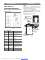
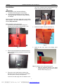
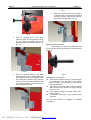
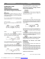
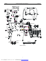
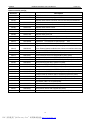
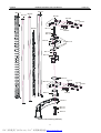
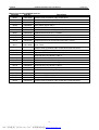
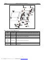
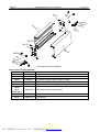
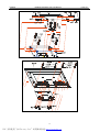
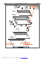
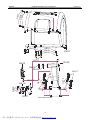
LAUNCH
KWB-408 Installation and Parts Manual
Table of Contents
Safety Precautions ......................................................................................................................................................... 1
Main Structure ................................................................................................................................................................ 2
Main structure spare parts ......................................................................................................................................... 2
Figure........................................................................................................................................................................... 2
Installation....................................................................................................................................................................... 3
Transport...................................................................................................................................................................... 3
Unpacking................................................................................................................................................................... 3
Positioning.................................................................................................................................................................... 3
Installation.................................................................................................................................................................... 4
Calibration and Adjustment........................................................................................................................................... 6
Self-calibration Program of the Balancer ..................................................................................................................... 6
Self-Testing Program (Testing Position Sensors and Indicators) ................................................................................. 6
Adjustment for Sensors and Inside Parameters........................................................................................................... 6
Parts List ......................................................................................................................................................................... 8
KWB-408 Main Wiring Diagrams................................................................................................................................. 22
PDF 文件使用 "pdfFactory Pro" 试用版本创建 www.fineprint.cn
LAUNCH
KWB-408 Installation and Parts Manual
Safety Precautions
Tools
To ensure the smooth installation and adjustment, please
get the following tools ready:
An adjustable wrench, a set of box wrenches, a pair of
scissors, a set of screwdrivers and a digital multi-meter
(measuring voltage).
Warning
l
l
l
l
This manual is an integral part of the product. Please
read it carefully.
Keep the manual for later use when maintaining the
machine.
This machine can only be used for the designed
purpose. Never use it for any other purpose.
The manufacturer is not responsible for any damage
incurred by improper use or use for the purposes other
than the intended one.
Before installing and adjusting the equipment, pay
attention to the following:
l
l
l
l
l
l
l
l
l
l
l
l
l
l
l
Safety Precautions
Read the two manuals carefully and thoroughly. Any
modifications to any components or parts, or use the
equipment for other purposes without either obtaining
permission from the manufacturer or observing the
instructions of the manuals may lead to direct or
indirect damage to the machine.
The installation and adjusting personnel should have
basic electrical knowledge.
Do not put KWB-408 in a place with extreme
temperature or moisture, or near the heating system,
water tap, air-humidifier or furnace.
Keep the machine from dust, ammonia, alcohol,
thinner or spray type binder.
KWB-408 should be installed on the even and stable
ground.
Avoid putting KWB-408 close to objects that may
cause vibration such as the air compressor.
KWB-408 should use individual power supply socket.
Do not plug other power supply wire into this socket.
The socket must be grounded safely. If the socket
does not have ground wire, please connect the ground
wire first.
Avoid any trample on power supply wire.
Keep 60cm distance between the back panel and the
wall for good ventilation. Enough room should be left
on both sides of KWB-408 for convenient operation.
Do not demount or refit the machine by yourself.
Avoid any impact with the rotary shaft.
Sundries should not be placed on the working desk.
During the normal operation, if abnormal noise, fog or
other noticeable phenomena occur, please turn off the
power switch and unplug the machine. Then, contact
relevant service personnel.
Enough space should be kept in front of the power
supply socket so that the plug can be quickly
disconnected in case of emergency.
Check the parts list carefully before installation. Please
contact the dealer or LAUNCH immediately if you have
any questions.
1
PDF 文件使用 "pdfFactory Pro" 试用版本创建 www.fineprint.cn
LAUNCH
KWB-408 Installation and Parts Manual
Main Structure
Figure
Main Structure
1. Measure scale — for automatic measurement of the
installation distance of the wheel and rim diameter, and the
accurate position of the sticking balance block.
2. Control panel — for man-machine dialogue.
3. Hanging handle-- For hanging conical casing, the wheel
width scale and other spare parts.
4. Counterweight groove —holder of the counterweight lead
block
5. Balance shaft — for supporting the wheel.
6. Wheel protection guard
Main structure spare parts are as
shown in Fig 1:
Wheel protection
guard
Control panel
Counterweight groove
Fig 1
Main structure parts list
Serial No.
ERP No.
Balance shaft
103200313
Description
KWB-408
supper-big
conical casing,45
103200316
KWB-408
casing,45
103200315
KWB-408 medium conical
casing,45
Ft04
103200297
KWB-408 small conical
casing,45
Ft06
103990018
Balance lead weight, 100g
Ft07
110040030
(417302) wheel balance
weight special pliers 10"
Ft08
104010485
KWB-408 quick locknut
104010311
KWB-408,
ABS
Ft01
Ft02
Ft03
Ft11
big
Measure scale
conical
Hanging handle
Fig 2
width
scale,
2
PDF 文件使用 "pdfFactory Pro" 试用版本创建 www.fineprint.cn
LAUNCH
KWB-408 Installation and Parts Manual
Installation
Installation
Transport
It is advisable to transport the machine with a forklift
(Fig. 4)
l Pay attention to the barycenter of the machine. Do not
tilt the machine much during the moving.
l Do not drive the forklift too fast.
l Keep the location of the machine on the forklift as low
as possible.
l Do not overturn it during the moving (pay attention to
the position of the barycenter).
Fig. 5
Attention:
Special anti-rust oil applied on the precise parts may attract
dust. Clean it when necessary.
Positioning
The installation position must satisfy the
requirement of safe work.
l
l
Fig.4
l
Unpacking
l
l
l
Open the packing box according to the Instruction on it.
Remove the packing materials (Fig. 5) and check
whether the machine is damaged during the
transportation. Confirm whether the main unit,
accessory parts, and relative materials are all
included.
Keep packing materials away from children. If the
packing materials may cause pollution, please dispose
them properly.
Remove accessories and spare parts supplied with the
machine and place them on a safe place. Then,
remove the cabinet fixed on bottom plate of packing
box and place them at a safe place.
l
l
The machine should be installed close to the main
power supply.
The machine should be installed on the even concrete
floor or other floors with hard surfaces. Adjust the
anchor bolts till KWB-408 is level and stable (Fig.6). In
order to fasten the machine reliably, use one M12×35
fastening bolt to fasten the machine on the floor tightly.
Otherwise, it will cause vibration and noise.
Enough spaces should be kept for operation and
maintenance. The space should be not less than 1m at
front and sides and 0.6m at rear to satisfy normal
operation of the machine.
If the machine is installed outdoors, the protective
shelter is necessary.
Keep the machine away from flammable gases.
Fig.6
Note:
¨ In order to use the machine safely and reasonably,
LAUNCH suggests installing the machine at least 0.6m
away from the wall.
3
PDF 文件使用 "pdfFactory Pro" 试用版本创建 www.fineprint.cn
LAUNCH
KWB-408 Installation and Parts Manual
rear of the computer board correspondingly (Fig.9).
Mount the rear cover of the control board.
Installation
l
l
Installation
Attention:
Please place, move, and store KWB-408 in
accordance with safety signs on the package
Never lift the rotary shaft when moving, installing or
operating KWB-408. Otherwise, the rotary shaft may
be damaged.
Make sure that the machine is stable and in good condition
after installation. Then install KWB-408 according to the
following Setup Instruction.
Step 1: Installation of the control panel
1. Take out the post board from the accessory box.
Unscrew the four screws on the board (Fig. 7) and
remove the rear cover of the board.
Fig.9
4.
Install the rear panel of the post board (Fig. 10).
Fig. 10
Fig. 7
2.
5.
Install the rear cover board of the display panel
(Fig.11).
Place the post pads between the cabinet and the post
panel, and then install the post panel on the rear of the
cabinet (Fig. 8).
Fig. 11
Step 2: Installation of the wheel protection guard
1. Install the supporting bracket of the wheel
protection guard on the rear part of the wheel
balancer cabinet body. (Fig. 12).
Fig. 8
3.
Take out the control panel from the accessory box.
Remove the rear cover of the panel (Fig. 8) and install
the control panel on the top of the post board.
Insert the two cable plugs into the interfaces on the
4
PDF 文件使用 "pdfFactory Pro" 试用版本创建 www.fineprint.cn
LAUNCH
KWB-408 Installation and Parts Manual
Installation
Fig.14
4.
Install the on-position switch. Insert the plug of
on-position switch on the supporting bracket of
the wheel protection guard into the connector
of the wheel balancer cabinet. (Fig. 15)
Fig. 12
2.
Insert the protective pipe of the wheel
protection guard into the supporting casing.
(Fig. 13). Fasten the protective pipe on the
supporting shaft by the washer and snap ring.
(Fig. 13)
Fig. 15
Step 3: Lead screw assembly
Please see (Fig. 16): Also you can remove the lead
screw, and then connect the flange pan to universal detent
(optional).
Fig.13
3.
Fig. 16
Install the extension spring of the wheel
protection guard. (Fig. 14) Firstly, please hook
the hanging pin of the wheel protection guard
with one end of the extension spring, and then
hook the pull screw on the supporting bracket
of the wheel protection guard with the other
end of the extension spring.
Step 4: Switch on the machine
l Check whether the power supply is in accordance with
the requirements of the data plate on the machine
before connection. All connection of circuit must be
done by professional.
l The socket of the power supply must be installed
within the reach of the operator. The height should be
set at 0.6—1.7m.
l If the supplied voltage is not stable, please use a
voltage regulator.
l The machine must have a good cabinet ground
connection.
Now you have finished the installation of KWB-408
successfully.
5
PDF 文件使用 "pdfFactory Pro" 试用版本创建 www.fineprint.cn
LAUNCH
KWB-408 Installation and Parts Manual
Calibration and Adjustment
after the balancer shutdown. The wheel balance operation
can be performed after above operating procedures.
Calibration and
Adjustment
Self-Testing Program (Testing Position
Sensors and Indicators)
Self-calibration Program of the Balancer
Press
key, from left to right, the indicators flash
one by one, and the control panel will display the
information as shown in Fig 20.
Attention:
The self-calibration program should be run after the
equipment’s first installation or if the measurement accuracy
of the equipment is uncertain, to ensure the measurement
accuracy of the balancer.
Turn on the power supply switch of the balancer, install a
wheel with medium size (13″--15″), input the data of the
Fig 20
The position sensor can be tested at that moment. Rotate
the wheel manually and slowly, indicator ALUI starts flashing,
and “0” will appear on the right screen when “0” position on
the main-shaft passes across the photoelectric sensor as
shown in Fig 21.
wheel rim and press
key at the same
time. The control panel will display the information as shown
in Fig 17.
Fig 21
Fig 17
Release
Once the wheel turns by one circle, the [0] will appear on
right screen one time. When the wheel rotates to the
reverse direction, the indicator ALUS will start flashing.
key, put down the wheel
Press
key, a number will be displayed on the right
screen, which is the distance between the inner side wall of
the wheel rim and the balancer cabinet. When moving the
measure scale, this number is changed, too.
protection guard, and press
key to rotate the
main-shaft. The control panel will display the information as
shown in Fig 18 when the main-shaft stops rotating.
Press
key, a number will be displayed on the left
screen, which is the diameter of the wheel rim. When
swaying the measure scale, this number is changed, too.
Fig 18
Adjustment for Sensors and Inside
Parameters
Put up the wheel protection guard, and attach 100g (3.5oz)
counterweight on the outside of the wheel rim. Put down the
Sensor Adjustment
Level sensor adjustment (Calibrate it after adjustment each
time, and then check it).
When the data at the inner side is larger, please move the
level sensor to the right. Release the nut at the inner side
first, and then screw the nut at the outside clockwise; when
the data at the inner side is smaller, please move the level
sensor to the left. Release the nut at the outside first, and
then screw the nut at the inner side counterclockwise.
wheel protection guard again, and press
key to
re-rotate the main-shaft. The control panel will display the
information as shown in Fig 19 when the main-shaft stops
rotating.
Adjustment for Inside Parameters
Fig 19
The self-calibration is finished, and the self-calibration data
is stored in computer memory, which cannot be lost even
Press
6
PDF 文件使用 "pdfFactory Pro" 试用版本创建 www.fineprint.cn
key, the control panel will display
LAUNCH
KWB-408 Installation and Parts Manual
the information as shown in Fig 22.
Fig 22
Press
key, the screen will be blackened, and
then press
key to enter the adjustment for inside
parameters; press
key to switch the inside
parameters: AnP, 1.-1, PHA and Pro, etc.
1. Adjustment for gram number error
When the displayed data is smaller than the actual
data, please adjust AnP higher (about two times of the
error value); adjust it smaller contrarily.
2. Keep 1.-1 between 0—5.
3. Phase error adjustment:
Rotate the wheel until all five indicators at the inner
side of the display panel are on. Observe whether the
counterweight is at the bottom of the wheel rim or not.
If it is, the phase value of PHA should not be changed;
otherwise, the phase value of PHA should be
increased or decreased.
4. Pro should be set to OFF.
Press
key to adjust the parameters.
7
PDF 文件使用 "pdfFactory Pro" 试用版本创建 www.fineprint.cn
Calibration and Adjustment
LAUNCH
KWB-408 Installation and Parts Manual
Parts List
This list is only for the reference of the maintenance
personnel. The manufacturer will not be held responsible for
any use other than the designed purpose.
In case of any damage of components and parts, please
contact your dealer or LAUNCH for replacement.
8
PDF 文件使用 "pdfFactory Pro" 试用版本创建 www.fineprint.cn
Parts List
LAUNCH
KWB-408 Installation and Parts Manual
Mm02
Mm 1 7
Mm 16
Mm 15
Parts List
Mm 01
Mm 0 7
Mm 1
9
Mm
Mm 22 0
1
Mm 18
Mm 0 8
Mm 14
Mm 2 2
Mm 2 3
Mm 2 4
M
m1
Mm 9
20
M
Mm 0 9
Mm 2
Mm 10
Mm 1
9
Mm
2
Mm 2 0
1
5
Mm 1
Mm 9
2
Mm 20
1
Mm 2 7
Mm 2 6
Mm 2 7
Mm 2 6
M m 03
Mm 28
Mm2 7
M m 28
Mm 11
Mm 2 6
M m28
m2 1
Mm 27
Mm 28
Mm 26
Mm04
Mm 29
M m 31
Mm 3 0
Mm 3 2
Mm 0 6
M m 13
Mm 1 7
M m1 7
Mm 16
Mm 15
Mm 05
Mm 16
Mm 1 5
Mm 12
Balancer Assembly
9
PDF 文件使用 "pdfFactory Pro" 试用版本创建 www.fineprint.cn
LAUNCH
KWB-408 Installation and Parts Manual
Parts List
Balancer assembly parts list
ERP No.
Serial No.
Mm01
104010520
Description
KWB-408 wheel balancer wheel protection guard
Mm02
206010276
KWB-408 wheel balancer display panel assembly
KWB-408 wheel balancer main-shaft, motor and cast steel parts assemblies
Mm03
Mm04
104010518
KWB-408 wheel balancer top cover
Mm05
206010336
KWB-408 wheel balancer measure scale assembly
Mm06
103201973
KWB-408 wheel balancer cabinet
Mm07
206010334
KWB-408 wheel balancer main board box assembly
Mm08
103201720
KWB-408 display panel post rear cover board
Mm09
103201706
KWB-408 display panel post
Mm10
206010280
KWB-408 wheel balancer power supply box assembly
Mm11
104010481
KWB-408 hanging handle
Mm12
102130018
Transformer 110V-60Hz ±9V or 220V-50Hz ±9V
Mm13
102100110
Ship shape switch, 32*25*33mm,R210-C5L-BR,16A/250VAC
Mm14
102020313
High-power dissipation resistance (insert plug-in), 4.2Ω,400W,±5%,Diameter:
47mm; Distance between installation holes: 300mm, with surface screw thread.
Mm15
103040012
Plain washer, GB97.1-85-4.0 (Nickel plated)
Mm16
103040011
Spring washer,GB/T93-1987,4.0(White zinc plated)
Mm17
103010077
Cross recessed pan head screw,GB818-85,M4*8 (Nickel plated)
Mm18
103020161
Hexagon socket cap head bolt, GB/T70-2000,M10*35 (Black zinc plated)
Mm19
103010077
Cross recessed pan head screw,GB818-85,M4*8 (Nickel plated)
Mm20
103040011
Spring washer,GB/T93-1987,4.0(White zinc plated)
Mm21
103040096
Plain washer, GB/T97.1-1985,10(White zinc plated)
Mm22
103040100
Spring washer, GB/T93-1976,10 (White zinc plated)
Mm23
103020147
Hexagon socket cap head bolt, GB/T5783-1986,M10*20(White zinc plated)
Mm24
103020079
Hexagon head bolt GB/T5781-1986 M12*35 (White zinc plated)
Mm25
103020161
Hexagon socket cap head bolt, GB/T70-2000,M10*35 (Black zinc plated)
Mm26
103010056
Cross recessed pan head screw, GB818-85,M4*12 (Black zinc plated)
Mm27
103040011
Spring washer, GB/T93-1987,4.0(White zinc plated)
Mm28
103040012
Plain washer, GB97.1-85-4.0 (Nickel plated)
Mm29
103201726
KWB-408 cabinet cover board
Mm30
103040012
Plain washer, GB97.1-85-4.0 (Nickel plated)
Mm31
103040011
Spring washer, GB/T93-1987,4.0(White zinc plated)
Mm32
103010077
Cross recessed pan head screw,GB818-85,M4*8 (Nickel plated)
10
PDF 文件使用 "pdfFactory Pro" 试用版本创建 www.fineprint.cn
30W
LAUNCH
KWB-408 Installation and Parts Manual
Parts List
Me 07
M e1 1
M e 09
M e 10
M e 06
Me05
M e02
M e01
M e1 2
M e 08
M e0 4
M e0 3
Me 13
M e1 4
M e 16
Me15
Me 17
M e1 8
M e1 9
M e05
Me20
M e 02
M e 01
M e 04
M e 03
A_2
M e2 1
Me22
Me 23
M e 24
M e 25
Measure Scale Assembly (KWB-408)
11
PDF 文件使用 "pdfFactory Pro" 试用版本创建 www.fineprint.cn
LAUNCH
KWB-408 Installation and Parts Manual
Parts List
Measure scale assembly (KWB-408) parts list
Serial No.
ERP No.
Description
Me01
103010380 Hexagon socket cap head bolt, GB/T70-1985, M4*24
Me02
103010570
Hexagon socket cap head nut, GB/T70-1985, M4
Me03
103030039
Hexagon nut, GB41-86-M6 (Black zinc plated)
Me04
103040027
Spring washer, GB/T93-1987, 6
Me05
103040063
Plain washer, GB/T97.1-1985,6 (White zinc plated)
Me06
103230197
KWB-408 measure scale rear support base
Me07
103230192
KWB-408 measure scale tie rod, L=526mm
Me08
104020069
KWB-408 scale, L=416mm
Me09
103201983
KWB-408 measure scale chrome-plate smooth shaft, L=540mm
Me10
103201983
KWB-408 measure scale chrome-plate smooth shaft, L=540mm
Me11
103110089
KWB-408 Tension spring, wire diameter: 0.8mm; outer diameter: 20mm*; total
length: 730mm
Me12
103010210
Hexagon socket cap head bolt, GB/T70-1985, M5*25 (White zinc plated)
Me13
103040099
Plain washer, GB/T97.1-1985,5 (White zinc plated)
Me14
103040073
Big washer GB/T96-1985,5 (White zinc plated)
Me15
103050006
Shaft using spring ring GB/T894.1-1986 15
Me16
103230196
KWB-408 measure scale slide base
Me17
103201984
KWB-408 measure scale slide bushing
Me18
103230198
KWB-408 measure scale linear bearing, inner D=8mm*outer D=15mm*L=24mm
Me19
103050012
Shaft using spring ring GB/T894.1-1986 24
Me20
103230195
KWB-408 measure scale front support base
Me21
104070064
KWB-408 measure scale fixing bushing, nylon
Me22
104010517
KWB-408 measure scale handle, ABS
Me23
103040099
Plain washer, GB/T97.1-1985,5 (White zinc plated)
Me24
103040027
Spring washer, GB/T93-1987, 6
Me25
103020160
Hexagon socket cap head bolt, GB/T70-1985, M5*14 (White zinc plated)
12
PDF 文件使用 "pdfFactory Pro" 试用版本创建 www.fineprint.cn
LAUNCH
KWB-408 Installation and Parts Manual
Parts List
Power Supply Box Assembly (KWB-408)
Power supply box assembly (KWB-408) parts list
Serial No.
ERP No.
Description
Pb01
103010087 Cross recessed countersunk head screw GB819.85, M4*10(White zinc plated)
Pb02
103010553
Cross recessed pan head screw, GB818-85,M4*12 (White zinc plated)
Pb03
103040011
Spring washer, GB/T93-1987,4.0 (White zinc plated)
Pb04
103040012
Plain washer, GB97.1-85-4.0 (Nickel plated)
Pb05
103201712
Right fixing plate
Pb06
Pb07
Pb08
Pb10
103230152
KWB-408 wheel balancer power supply box
Pb09
102160358
Hexagon head plastic clip button, height: 18mm,up Ф3mm,down Ф8mm
Pb11
103201712
Left fixing plate
13
PDF 文件使用 "pdfFactory Pro" 试用版本创建 www.fineprint.cn
LAUNCH
KWB-408 Installation and Parts Manual
Mb
Mb
Parts List
Mb
06
01
Mb
Mb 0 02
Mb 0 3
4
07
Mb
05
Mb 08
Mb 10
Mb
Mb 01
09
Mb
Mb 11
M 04
M bb 0 3
02
Main Board Box Assembly (KWB-408)
Main board box assembly (KWB-408)
Serial No.
ERP No.
Description
Mb01
103010087 Cross recessed countersunk head screw GB819.85, M4*10(White zinc plated)
Mb02
103010553 Cross recessed pan head screw, GB818-85,M4*12 (White zinc plated)
Mb03
103040011
Spring washer, GB/T93-1987,4.0 (White zinc plated)
Mb04
103040012
Plain washer, GB97.1-85-4.0 (Nickel plated)
Mb05
103201712
Right fixing plate
Mb06
Mb07
Mb09 Mb10
103230194
KWB-408 wheel balancer main board box
Mb08
102160358
Hexagon head plastic clip button, height: 18mm,up Ф3mm,down Ф8mm
Mb11
103201712
Left fixing plate
14
PDF 文件使用 "pdfFactory Pro" 试用版本创建 www.fineprint.cn
LAUNCH
KWB-408 Installation and Parts Manual
Display Panel Assembly 1
Display Panel Assembly 2
15
PDF 文件使用 "pdfFactory Pro" 试用版本创建 www.fineprint.cn
Parts List
LAUNCH
KWB-408 Installation and Parts Manual
Display Panel Assembly 3
16
PDF 文件使用 "pdfFactory Pro" 试用版本创建 www.fineprint.cn
Parts List
LAUNCH
KWB-408 Installation and Parts Manual
Display panel assembly parts list
Serial No.
ERP No.
Dp01
103201725
Parts List
Description
KWB-408 display panel mount rear cover
Dp02
103040012
Plain washer, GB97.1-85-4.0 (Nickel plated)
Dp03
103040011
Spring washer, GB/T93-1987,4.0 (White zinc plated)
Dp04
103010056
Cross recessed pan head screw, GB818-85,M4*12 (Black zinc plated)
Dp05
103201723
KWB-408 display panel wire clip
Dp06
103201724
KWB-408 display panel casing mount
Dp07
104010486
KWB-408 display panel bottom casing, ABS
Dp08
103010063
Cross recessed pan head screw,GB819-85,M3*6 (White zinc plated)
Dp09
103040009
Spring washer, GB/T93-1987, 3.0 (Nickel plated)
Dp10
103040016
Plain washer, GB97.1-1985-3.0, silver color (Nickel plated)
Dp11
103201722
KWB-408 display panel inner scale-board
Dp12
103010045
Cross recessed pan head tapping screw, GB845-85,ST3*12(Brunofix)
Dp13
205010328
KWB-412 wheel balancer display circuit board
Dp14
103201721
KWB-408 film support plate
Dp15
107040085
KWB-408 display panel film
Dp16
104010482
KWB-408 display panel surface shell, ABS
Dp17
103040012
Plain washer, GB97.1-85-4.0 (Nickel plated)
Dp18
103040011
Spring washer, GB/T93-1987,4.0 (White zinc plated)
Dp19
103010056
Cross recessed pan head tapping screw,M4*12
17
PDF 文件使用 "pdfFactory Pro" 试用版本创建 www.fineprint.cn
KWB-408 Installation and Parts Manual
Parts List
Ob 0
7
O b0
O b0 8
9
LAUNCH
Ob 10
Ob 07
Ob 08
Ob 09
Ob 01
Ob 11
O b 02
Ob 03
O b 05
Ob 06
Ob 12
Ob 13
14
Ob 17
14
b
Ob
O
Ob 15
Ob 16
O b 13
Ob 12
O b 04
Turnover Case Assembly
18
PDF 文件使用 "pdfFactory Pro" 试用版本创建 www.fineprint.cn
LAUNCH
KWB-408 Installation and Parts Manual
Turnover case assembly parts list
Serial No.
ERP No.
Ob01
104010520
Parts List
Description
KWB-408 wheel balancer wheel protection guard
103201980
KWB-408 wheel protection guard turnover bracket
Ob03
103110090
KWB-408 wheel protection guard extension spring, wire D= 4mm* outer
D=29mm*total L=134mm
Ob04
102100121
Stroke switch, ME-8104
Ob05
103050044
Ob06
103050052
Spring ring, GB/T894.2-1986 30
KWB-408 wheel protection guard big washer, φ37
Ob07
103010056
Cross recessed pan head screw, GB818-85, M4*12 (Black zinc plated)
Ob08
103040011
Spring washer, GB/T93-1987, 4.0 (White zinc plated)
Ob09
103040012
Plain washer, GB/T97.1-1985,6 (Nickel plated)
Ob10
103030061
Hexagon nut (Zinc plated), GB/T6170-1986 M8
Ob11
103010260
Hexagon stud head screw, GB/T70-1985 M8*20
Ob12
103020056
Hexagon bolt, GB/T5783-1986 M10*30 (Brunofix)
Ob13
103040100
Spring washer, GB/T93-1976, 10 (plated)
Ob14
103040096
Plain washer, GB/T97.1-1985, 10 (White zinc plated)
Ob15
103010380
Hexagon stud head screw, GB/T70-1985 M4*20
Ob16
103010570
Hexagon stud head screw, GB/T70-1985 M4*30
Ob17
103040012
Plain washer, GB/T97.1-1985,6 (Nickel plated)
Ob02
19
PDF 文件使用 "pdfFactory Pro" 试用版本创建 www.fineprint.cn
Ms0 7
Ms0 5
Ms0 6
Ms38
Ms 10 Ms09 Ms08
Ms37
M s27
M s25
Cast Steel Parts, Motor and Shaft Assemblies
Ms28
M s29
Ms30
Ms1 3
PDF 文件使用 "pdfFactory Pro" 试用版本创建 www.fineprint.cn
Ms0 2
Ms0 3
Ms31
M s22
M s2 4
Ms23
M s26
M s22
M s24
Ms23
Ms36
Ms12
Ms 11
M s17
Ms16
M s34
M s21
M s35
M s21
M s33
M s33
M s21
20
Ms01
Ms0 2
Ms0 3
Ms0 4
Ms15
M s21
M s20
M s19
M s14
M s18
M s32
M s1 9
M s19
M s32
Ms3 1
M s33
Ms19
Ms32
Ms21
Ms0 1
Ms0 2
Ms0 3
Ms0 4
Ms21
Ms32
Ms19
Ms33
Parts List
KWB-408 Installation and Parts Manual
LAUNCH
M s3 6
LAUNCH
KWB-408 Installation and Parts Manual
Parts List
Cast steel parts, motor and shaft assemblies parts list
Serial No.
ERP No.
Description
Ms01
103020079
Hexagon head bolt GB/T5781-1986 M12*35 (White zinc plated)
Ms02
103040044
Spring washer (Zinc plated), GB/T93-1987 12
Ms03
103040112
Plain washer (Zinc plated), GB/T97.1-1985,12
Ms04
104130256
KWB-408 cast steel part cushion, ф30*3mm,
Ms05
103201699
KWB-408 wheel balancer cast steel parts
Ms06
103201700
KWB-408 motor fixing plate
Ms07
102990092
KWB-408 motor (110V,60HZ,1360r/min)0.37KW,MY7124/B14
Ms08
103010551
Hexagon socket cap screw M6*28
Ms09
103040027
Spring washer, GB/T93-1987 6
Ms10
103040063
Plain washer, GB/T97.1-1985,6 (White zinc plated)
Ms11
103010552
Hexagon socket cap screw M5*18
Ms12
103040003
Spring washer GB/T93-1987 5
Ms13
103040099
Plain washer, GB/T97.1-1985,5 (White zinc plated)
Ms14
103030009
Hexagon nut GB/T6170-1986 M4 (White zinc plated)
Ms15
103040012
Plain washer, GB97.1-85-4.0 (Nickel plated)
Ms16
103040011
Spring washer, GB/T93-1987,4.0 (White zinc plated)
Ms17
103010087
Cross recessed countersunk head screw,GB/T819-1985,M4*10 (White zinc
plated)
Ms18
103020161
Hexagon socket cap bolt, GB/T70-2000,M10*35 (Black zinc plated)
Ms19
103040096
Plain washer, GB/T97.1-1985,10 (White zinc plated)
Ms20
103040100
Spring washer, GB/T93-1976,10 (White zinc plated)
Ms21
103030062
Hexagon nut, GB/T6170-1986,M10 (White zinc plated)
Ms22
103010035
Cross recessed pan head screw, GB818-85,M3*10 (Nickel plated)
Ms23
103040016
Plain washer, GB/T97.1-1985,3,silver color, (Nickel plated)
Ms24
103040009
Spring washer, GB/T93-1987,3.0, (Nickel plated)
Ms25
103030010
Nut, GB6170-86-M3 (White zinc plated)
Fixing plate 2
Ms26
Ms27
z205010327
KWB-412 wheel balancer raster board PCA
Fixing plate 1
Ms28
Ms29
206010335
KWB-408 wheel balancer main-shaft assembly
Ms30
103200304
KWB-408 thread bar (invented)
Ms31
102170042
KWB-408 piezoelectric pottery sensor set
Ms32
103040084
Outer gear lock washer,GB/T862.1-1987,10 (White zinc plated)
Ms33
101010058
KWB-408 sensor washer Q235
Ms34
103260061
KWB-408 sleeve screw
Ms35
103020052
KWB-408 sensor bolt
Ms36
X103110087
Ms37
104070065
KWB-408 main shaft spring fixing washer, nylon
Ms38
103050053
KWB-408 Main shaft hole using spring ring, Ф125
KWB-408 main compressed spring, 65Mn (invented)
21
PDF 文件使用 "pdfFactory Pro" 试用版本创建 www.fineprint.cn
LAUNCH
KWB-408 Installation and Parts Manual
KWB-408 Main Wiring Diagrams
Main-board box interface diagram:
Power supply box interface diagram:
22
PDF 文件使用 "pdfFactory Pro" 试用版本创建 www.fineprint.cn
Circuit Diagram
LAUNCH
KWB-408 Installation and Parts Manual
Circuit Diagram
Cables connected to main-board box interface diagram:
Wirings from DB9 of main-board to main-shaft sensor:
Color of Core cable
DB9 Male
Signal
Green
1Pin
Level Sensor
(Positive)
Yellow
2Pin
Level Sensor
(Negative)
Black
3Pin
Vertical Sensor
(Negative)
Red
4Pin
Vertical Sensor
(Positive)
23
PDF 文件使用 "pdfFactory Pro" 试用版本创建 www.fineprint.cn
LAUNCH
KWB-408 Installation and Parts Manual
Circuit Diagram
The diagram of interfaces at main-board box inside to the display and key-presses:
The diagram of the raster connector inside the main-board box:
M-Se nso r
(fem a le )
9
5
1
6
1
M-Se nso r
1Pin
2/3Pin
4Pin
3
24
PDF 文件使用 "pdfFactory Pro" 试用版本创建 www.fineprint.cn
LAUNCH
KWB-408 Installation and Parts Manual
Circuit Diagram
The diagram of power supply connector inside the main-board box:
1
M-Po we r
1Pin
2Pin
3Pin
4Pin
5Pin
5
The diagram of raster connector inside the main-board box:
25
PDF 文件使用 "pdfFactory Pro" 试用版本创建 www.fineprint.cn
LAUNCH
KWB-408 Installation and Parts Manual
Power supply board to external components wiring diagram:
26
PDF 文件使用 "pdfFactory Pro" 试用版本创建 www.fineprint.cn
Circuit Diagram