1
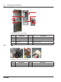
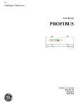
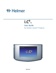
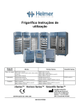
Refrigerator Operation Manual i.Series™ and Horizon Series™ Blood Bank Models • i.Series: iB111 (Version B); iB120, iB125, iB245, iB256 (Version C) • Horizon Series: HB111 (Version B); HB120, HB125, HB245, HB256 (Version C) Laboratory Models • i.Series: iLR111 (Version B); iLR120, iLR125, iLR245, iLR256 (Version C) • Horizon Series: HLR111 (Version B); HLR120, HLR125, HLR245, HLR256 (Version C) Pharmacy Models • i.Series: iPR111 (Version B); iPR120, iPR125, iPR245, iPR256 (Version C) • Horizon Series: HPR111 (Version B); HPR120, HPR125, HPR245, HPR256 (Version C) Model S/N HELMER SCIENTIFIC 14400 Bergen Boulevard Noblesville, IN 46060 USA Phone +1 (317) 773-9073 USA and Canada (800) 743-5637 0086 ISO 13485:2003 CERTIFIED 360126-1/D i Contents Section I: General Information. . . . . . . . . . . . . . . . . . . . . . . . . . . . . . . . . . . . . . 1 1 About this Manual . . . . . . . . . . . . . . . . . . . . . . . . . . . . . . . . . . . . . . . . . . . . . . . . . . . . . . . . 3 2Safety . . . . . . . . . . . . . . . . . . . . . . . . . . . . . . . . . . . . . . . . . . . . . . . . . . . . . . . . . . . . . . . . . . 4 2.1 2.2 Labels . . . . . . . . . . . . . . . . . . . . . . . . . . . . . . . . . . . . . . . . . . . . . . . . . . . . . . . . . . . . . . . . . . . . . . . . . . 4 Avoiding injury. . . . . . . . . . . . . . . . . . . . . . . . . . . . . . . . . . . . . . . . . . . . . . . . . . . . . . . . . . . . . . . . . . . . 4 3Installation . . . . . . . . . . . . . . . . . . . . . . . . . . . . . . . . . . . . . . . . . . . . . . . . . . . . . . . . . . . . . . 5 3.1 3.2 Location requirements. . . . . . . . . . . . . . . . . . . . . . . . . . . . . . . . . . . . . . . . . . . . . . . . . . . . . . . . . . . . . . 5 Preparing the temperature probes. . . . . . . . . . . . . . . . . . . . . . . . . . . . . . . . . . . . . . . . . . . . . . . . . . . . . 5 4 Compliance and Energy Conservation . . . . . . . . . . . . . . . . . . . . . . . . . . . . . . . . . . . . . . . 7 Section II: i.Series™ Models. . . . . . . . . . . . . . . . . . . . . . . . . . . . . . . . . . . . . . . . 9 5Components. . . . . . . . . . . . . . . . . . . . . . . . . . . . . . . . . . . . . . . . . . . . . . . . . . . . . . . . . . . . 11 5.1 5.2 5.3 Front and chamber. . . . . . . . . . . . . . . . . . . . . . . . . . . . . . . . . . . . . . . . . . . . . . . . . . . . . . . . . . . . . . . . 11 Rear. . . . . . . . . . . . . . . . . . . . . . . . . . . . . . . . . . . . . . . . . . . . . . . . . . . . . . . . . . . . . . . . . . . . . . . . . . . 12 Top. . . . . . . . . . . . . . . . . . . . . . . . . . . . . . . . . . . . . . . . . . . . . . . . . . . . . . . . . . . . . . . . . . . . . . . . . . . . 12 6 General Operation. . . . . . . . . . . . . . . . . . . . . . . . . . . . . . . . . . . . . . . . . . . . . . . . . . . . . . . 13 6.1 6.2 6.3 6.4 6.5 6.6 6.7 6.8 6.9 6.10 Power on. . . . . . . . . . . . . . . . . . . . . . . . . . . . . . . . . . . . . . . . . . . . . . . . . . . . . . . . . . . . . . . . . . . . . . . 13 Storing items in the refrigerator. . . . . . . . . . . . . . . . . . . . . . . . . . . . . . . . . . . . . . . . . . . . . . . . . . . . . . 13 Locking and unlocking the doors. . . . . . . . . . . . . . . . . . . . . . . . . . . . . . . . . . . . . . . . . . . . . . . . . . . . . 13 Using access control. . . . . . . . . . . . . . . . . . . . . . . . . . . . . . . . . . . . . . . . . . . . . . . . . . . . . . . . . . . . . . 13 Moving drawers, shelves, and baskets . . . . . . . . . . . . . . . . . . . . . . . . . . . . . . . . . . . . . . . . . . . . . . . . 14 Changing temperature setpoints. . . . . . . . . . . . . . . . . . . . . . . . . . . . . . . . . . . . . . . . . . . . . . . . . . . . . 14 Understanding normal operation. . . . . . . . . . . . . . . . . . . . . . . . . . . . . . . . . . . . . . . . . . . . . . . . . . . . . 14 Identifying active visual alarms . . . . . . . . . . . . . . . . . . . . . . . . . . . . . . . . . . . . . . . . . . . . . . . . . . . . . . 15 Controlling the sound for audible alarms. . . . . . . . . . . . . . . . . . . . . . . . . . . . . . . . . . . . . . . . . . . . . . . 15 Turning the light on and off . . . . . . . . . . . . . . . . . . . . . . . . . . . . . . . . . . . . . . . . . . . . . . . . . . . . . . . . . 15 7 Maintenance Schedule . . . . . . . . . . . . . . . . . . . . . . . . . . . . . . . . . . . . . . . . . . . . . . . . . . . 16 8 Technical Specifications. . . . . . . . . . . . . . . . . . . . . . . . . . . . . . . . . . . . . . . . . . . . . . . . . . 17 Section III: Horizon Series™ Models. . . . . . . . . . . . . . . . . . . . . . . . . . . . . . . . 19 9Components. . . . . . . . . . . . . . . . . . . . . . . . . . . . . . . . . . . . . . . . . . . . . . . . . . . . . . . . . . . . 21 9.1 9.2 9.3 Front and chamber. . . . . . . . . . . . . . . . . . . . . . . . . . . . . . . . . . . . . . . . . . . . . . . . . . . . . . . . . . . . . . . . 21 Rear. . . . . . . . . . . . . . . . . . . . . . . . . . . . . . . . . . . . . . . . . . . . . . . . . . . . . . . . . . . . . . . . . . . . . . . . . . . 22 Top. . . . . . . . . . . . . . . . . . . . . . . . . . . . . . . . . . . . . . . . . . . . . . . . . . . . . . . . . . . . . . . . . . . . . . . . . . . . 22 360126-1/D ii Refrigerator Operation Manual 10 General Operation. . . . . . . . . . . . . . . . . . . . . . . . . . . . . . . . . . . . . . . . . . . . . . . . . . . . . . . 23 10.1 10.2 10.3 10.4 10.5 10.6 10.7 10.8 10.9 10.10 Power on. . . . . . . . . . . . . . . . . . . . . . . . . . . . . . . . . . . . . . . . . . . . . . . . . . . . . . . . . . . . . . . . . . . . . . . 23 Storing items in the refrigerator. . . . . . . . . . . . . . . . . . . . . . . . . . . . . . . . . . . . . . . . . . . . . . . . . . . . . . 23 Locking and unlocking the doors. . . . . . . . . . . . . . . . . . . . . . . . . . . . . . . . . . . . . . . . . . . . . . . . . . . . . 23 Using access control. . . . . . . . . . . . . . . . . . . . . . . . . . . . . . . . . . . . . . . . . . . . . . . . . . . . . . . . . . . . . . 23 Moving drawers, shelves, and baskets . . . . . . . . . . . . . . . . . . . . . . . . . . . . . . . . . . . . . . . . . . . . . . . . 23 Changing temperature controller setpoints . . . . . . . . . . . . . . . . . . . . . . . . . . . . . . . . . . . . . . . . . . . . . 24 Changing temperature alarm setpoints. . . . . . . . . . . . . . . . . . . . . . . . . . . . . . . . . . . . . . . . . . . . . . . . 25 Identifying active visual alarms . . . . . . . . . . . . . . . . . . . . . . . . . . . . . . . . . . . . . . . . . . . . . . . . . . . . . . 25 Controlling the sound for audible alarms. . . . . . . . . . . . . . . . . . . . . . . . . . . . . . . . . . . . . . . . . . . . . . . 26 Turning the light on and off . . . . . . . . . . . . . . . . . . . . . . . . . . . . . . . . . . . . . . . . . . . . . . . . . . . . . . . . . 26 11 Maintenance Schedule . . . . . . . . . . . . . . . . . . . . . . . . . . . . . . . . . . . . . . . . . . . . . . . . . . . 27 12 Technical Specifications. . . . . . . . . . . . . . . . . . . . . . . . . . . . . . . . . . . . . . . . . . . . . . . . . . 28 360126-1/D Section I: General Information Section I: General Information 360126-1/D 1 2 Refrigerator Operation Manual This page left blank intentionally. 360126-1/D General Information: About this Manual 1 About this Manual 3 This chapter explains the symbols and conventions used in this manual, copyright information about this document, and trademark information for products supplied by Helmer. 1.1 Intended audience This manual is intended for use by end users of the refrigerator, and is to be used in conjunction with the i.C³™ User Guide, Refrigerator Service Manual, Chart Recorder Operation Manual, and Horizon Access Control Keypad User Guide, available on the CD shipped with the refrigerator. 1.2 Symbols and conventions 1.2.1Cautions A Caution is used to call attention to a condition or possible situation that could damage or destroy the equipment or the operator’s work. ! Caution Temperature probes are fragile. Handle them with care. 1.2.2Notes Notes contain additional information about a topic. Notes are used to provide information about how a topic relates to another topic, or background information about a design characteristic. Note 1.2.3 Spare parts are available for purchase through Helmer. Model references Generic references are used throughout this manual to group models that contain similar features. For example, “125 models” refers to all models of that size (iB125, HB125, iLR125, HLR125, iPR125, HPR125). This manual covers all upright refrigerators, which may be identified singly, by their size, or by their respective “Series.” Model Group i.Series Horizon Series Blood Bank iB111, iB120, iB125, iB245, iB256 HB111, HB120, HB125, HB245, HB256 Laboratory iLR111, iLR120, iLR125, iLR245, iLR256 HLR111, HLR120, HLR125, HLR245, HLR256 Pharmacy iPR111, iPR120, iPR125, iPR245, iPR256 HPR111, HPR120, HPR125, HPR245, HPR256 EC 1.3 REP Emergo Europe Molenstraat 15 2513 BH The Hague, Netherlands Copyright and trademark information Helmer®, i.Series®, i.C³™, Horizon Series™, and Rel.i™ are registered trademarks or trademarks of Helmer, Inc. in the United States of America. Copyright © 2013 Helmer, Inc. All other trademarks and registered trademarks are the property of their respective owners. 360126-1/D 4 Refrigerator Operation Manual 2Safety This chapter describes general safety information for operating the refrigerator. The Refrigerator Service Manual includes additional safety information for maintaining and cleaning the refrigerator. Your organization may provide additional safety information. 2.1Labels Caution, risk of danger Caution, hot surface Caution, unlock all casters 2.2 Caution, shock hazard Earth ground terminal Protective earth ground terminal Avoiding injury ► ► ► ► ► Review safety instructions before installing, using, or maintaining the equipment. Before performing procedures, review any specific safety instructions. Do not open multiple, loaded drawers at the same time. Before moving unit, ensure casters are free of debris. Do not move a unit whose load exceeds 900 lbs/408 kg (single door units) or 1350 lbs/612 kg (doubledoor units). ► Avoid removing electrical service panels and access panels unless so instructed. ► Use supplied power cords only. ► Notify appropriate safety personnel when handling or disposing of materials that are infectious, toxic, pathological, radioactive, or otherwise biologically or environmentally harmful. ! Caution 360126-1/D Decontaminate parts prior to sending for service or repair. Items not decontaminated appropriately will not be accepted. Documentation stating contents are not contaminated and are safe to handle must accompany returns. Contact Helmer or your distributor for decontamination instructions and a Return Authorization Number. General Information: Installation 3Installation 3.1 5 Location requirements ► ► ► ► Has a grounded outlet meeting the electrical requirements as listed on the product specification label Is clear of direct sunlight, high temperature sources, heating vents, and air conditioning vents Has a minimum of 8 inches (203 mm) above, and a minimum of 3 inches (76 mm) behind Meets the limits specified for ambient temperature and relative humidity Placement ! Caution ► Do not use the water evaporation tray, located on the rear of the refrigerator, as a handle. The tray may be hot. ► To prevent tipping, ensure the casters are unlocked, leveling feet (if installed) are lifted, and the doors are closed before moving the refrigerator. 1 Ensure all casters are unlocked and doors are closed. 2 Roll refrigerator into place and lock casters. 3 Ensure refrigerator is level. Note Helmer recommends the use of leveling feet. Operating conditions This refrigerator is designed for indoor use only. Altitude (maximum): 2000 m Ambient temperature range: 15 °C to 32 °C Relative humidity (maximum for ambient temperature): 80% for temperatures up to 31 °C, decreasing linearly to 50% at 40 °C Temperature control range: 2 °C to 10 °C 3.2 Preparing the temperature probes Temperature probes monitor chamber temperature. Number and location of probes varies by model. In addition to using standard probes installed by Helmer, external probes may be introduced through existing top ports and immersed in existing probe bottles. Probes can also be inserted through a side access port (availability varies by model). For each probe bottle, obtain: ► Approximately 4 oz (120 ml) of product simulation solution. Solution is a 10:1 ratio of water to glycerin. Left: Probe bottle with temperature and chart recorder probes. Middle: Access port on top of refrigerator. Right: Access port on side of refrigerator. The number and location of ports varies by model. 360126-1/D 6 Refrigerator Operation Manual To fill a temperature probe bottle ! Caution 1 2 3 4 ► Clean bottle first, as required. ► Temperature probes are fragile; handle with care. Remove all probes from bottle. Remove bottle from bracket and fill with approximately 4 oz (120 ml) of product simulation solution. Cap tightly to minimize evaporation. Place bottle in bracket and replace probes, immersing at least 2 inches (50 mm) in solution. 360126-1/D General Information: Compliance and Energy Conservation 4 Compliance and Energy Conservation Energy conservation and regulatory compliance This device complies with the requirements of directive 93/42/EEC concerning Medical Devices, as amended by 2007/47/EC. This product is certified to applicable UL and CSA standards by a NRTL. 0086 Insulation Type: 2 Pollution Degree: 2 (for use in USA and Canada only) Sound level is less than 70 dB(A). WEEE compliance The WEEE (waste electrical and electronic equipment) symbol (right) indicates compliance with European Union Directive WEEE 2002/96/EC and applicable provisions. The directive sets requirements for the labeling and disposal of certain products in affected countries. When disposing of this product in countries affected by this directive: ► Do not dispose of this product as unsorted municipal waste. ► Collect this product separately. ► Use the collection and return systems available locally. For more information on the return, recovery, or recycling of this product, contact your local distributor. 360126-1/D 7 8 Refrigerator Operation Manual This page left blank intentionally. 360126-1/D Section II: i.Series™ Models Section II: i.Series™ Models 360126-1/D 9 10 Refrigerator Operation Manual This page left blank intentionally. 360126-1/D i.Series™ Models: Components 5Components 5.1 11 Front and chamber I J A B C D E F G H Chamber and front features (iLR120 model shown). Label A B C D E F 5.1.1 Description Door lock i.C³ control USB port Upper probe bottle Unit cooler with fan guard Label G H I J Not shown Description Lower probe bottle (excluding 111 models) Caster Standard for adjusting storage components Drawer/basket slide Chart recorder (standard on blood bank models, optional on laboratory and pharmacy models) Shelf Access Control option A Access Control lock cartridge (iB120 model shown). Label Description A Access Control cartridge assembly (includes manual override key) 360126-1/D 12 Refrigerator Operation Manual 5.2Rear A G B H I J C D E K F L M Rear features (iB111 model shown). Label A B C D E F G Description Condenser grill Drain line Product specification label Power cord Condensate evaporator Water evaporation tray Remote alarm interface Label H I J K L M Description RJ-45 Ethernet port USB port RS-232 COM port (optional) Backup battery switch Main power switch Circuit breakers (230 V models) 5.3Top A B C D Top features (i.Series model shown). Label A B Description Condenser Compressor 360126-1/D Label Description C Monitor backup battery D Access port (number and location vary by model) i.Series™ Models: General Operation 6 General Operation 6.1 Power on Note 13 Allow the refrigerator to come to room temperature before power on. When the power is connected for the first time, the refrigerator runs frequently to achieve normal operating temperature. This may cause an alarm to sound. When normal operating temperature is reached, the refrigerator runs normally and automatically clears the alarm. The refrigerator a rechargeable backup battery that is switched off for shipping. Switch the battery ON to provide power to the monitoring system in the event of main power failure. ! Caution Do not remove the cover from the condensate evaporator tray. 1 Plug the power cord into a grounded outlet that meets the electrical requirements that appear on the product specification label. 2 Switch the AC ON/OFF switch ON. The touchscreen lights up. For more information, refer to the i.C³ User Guide. Note The i.C³ monitoring and control system will take approximately two minutes to boot up. 3 If an alarm sounds, mute the alarm temporarily by touching the Mute button. 4 Switch the backup battery switch ON. Note 6.2 Active alarms are displayed on the Home screen. If an alarm condition other than High Temperature has occurred, refer to the service manual for troubleshooting procedures. Storing items in the refrigerator ! Caution Follow all chemical handling and disposal requirements and procedures specified by your organization. See Chapter 2 (Safety). Before storing items in the refrigerator, be sure the temperature is correct and stable. After the refrigerator has reached room temperature, allow the chamber temperature to stabilize at the setpoint before storing product. 6.3 Locking and unlocking the doors Lock the doors to prevent unauthorized access to items stored in the refrigerator. The refrigerator is shipped from the factory with two keys. 6.4 Using access control The Access Control option allows user-specific secure access to the refrigerator. The Access Control system consists of a mechanical lock which prevents the refrigerator door from being opened unless a valid user code is entered on the i.C³ Access Control screen. If the Access Control option has been installed and is enabled, refer to the i.C³ User Guide. 360126-1/D 14 6.5 Refrigerator Operation Manual Moving drawers, shelves, and baskets Not all containers are available for all models. The drawers, shelves, or baskets may be removed or replaced as needed. Refer to the service manual for additional information. NOTE 6.6 Do not move a unit whose load exceeds 900 lbs/408 kg (single door units) or 1350 lbs/612 kg (double-door units). Changing temperature setpoints The refrigerator is shipped from the factory with preset temperature setpoints. These setpoints are specific to the refrigerator’s intended use. Instructions for changing the temperature setpoints are outlined within Chapter 11: Alarm Settings, in the i.C³ User Guide. Refer to the i.C³ User Guide for instructions in changing temperature setpoints. 6.7 Understanding normal operation This sub-chapter describes some of the characteristics of the refrigerator during normal operation. 6.7.1 Understanding when the Home screen appears The i.C³ displays the Home screen if the Home button is touched from any other screen. If another screen is displayed and there is no interaction for two minutes, the display returns to the Home screen. The only exceptions are the screens used to enter a password. For more information about the i.C³ Home screen, refer to the i.C³ User Guide. Home screen. 6.7.2 Understanding the temperature graph screensaver Home screen with temperature graph. The temperature graph screen saver displays chamber temperature data for the past 24 hours of operation. When there are no active alarms and the Home screen has not been touched for one minute, the graph appears at the bottom of the screen. The graph clears if the screen is touched or an alarm activates. For more information about the i.C³ temperature graph screensaver, refer to the i.C³ User Guide. 360126-1/D i.Series™ Models: General Operation 6.8 15 Identifying active visual alarms ► If any alarms are active, the Alarm Condition indicator appears, with the type of alarm described below it. ► If multiple alarms are active, they are sequentially displayed for two seconds each, below the Alarm Condition indicator. ► If the alarm is for the chamber temperature, the display of the upper chamber temperature turns red. For more information about the i.C³ alarms, refer to the i.C³ User Guide. Home screen with an active High Temperature alarm. 6.9 Controlling the sound for audible alarms All audible alarms or the muting period on an active audible alarm may be controlled. Muting and disabling audible alarms :15 Mute button. Left: Alarm is not muted. Right: Button shown with 15-minute delay indicator. Audible alarms may be muted temporarily by touching the Mute button until the desired duration is shown. For more information about the i.C³ alarms, refer to the i.C³ User Guide. To mute an active audible alarm ► Touch the Mute button. The alarm is muted for five minutes. If the alarm is still active after five minutes, the audible alarm is resumed. 6.10 Turning the light on and off The Light button for the chamber is located on the monitoring system screen. Light button. 360126-1/D 16 Refrigerator Operation Manual 7 Maintenance Schedule Maintenance tasks should be completed according to the following schedule. Refer to the service manual and the i.C³ User Guide for more detail on the various tasks. Note These are recommended minimum requirements. Regulations for your organization or physical conditions at your organization may require maintenance items to be performed more frequently, or only by designated service personnel. Task Test the high and low temperature alarms. Test the power failure alarm (as required by your organization’s protocols). Test the door alarm (as required by your organization’s protocols). Check the temperature calibration on the monitor and change it if necessary. (Models with chart recorders) Check the backup battery for the chart recorder after an extended power failure and change it if necessary, or change the battery if it has been in service for one year. Refer to the Temperature Chart Recorder Operation and Service Manual. Check the level of the solution in the probe bottles. Refill or replace solution if necessary. Examine the probe bottles and clean or replace them if necessary. Check the chamber lights and replace them if necessary. Clean the condenser grill. Frequency Quarterly Annually As needed Clean the door gaskets, interior, and exterior of the refrigerator. If applicable, test the ground fault circuit interrupter on the internal outlet. Note Cleaning of the condenser grill is required on a quarterly basis. ! Caution ► During a power failure, the rechargeable backup battery provides power to the monitoring system and the power failure alarm. If the backup battery is not functioning, the power failure alarm will not be activated. ► If the rechargeable backup battery does not provide power to the monitoring system during the power failure alarm test, or if the battery has been in service for two years, replace the battery. ! Caution Follow all chemical handling and disposal requirements and procedures specified by your organization. See Chapter 2 (Safety). 360126-1/D i.Series™ Models: Technical Specifications 8 Technical Specifications Power Input voltage and frequency The requirements for a particular refrigerator are specified on the product specification label. The voltage tolerance is ±10% of the nominal voltage. Available options are 115 V 60 Hz; 230 V 50 Hz, and 230 V 60 Hz. Power consumption The power consumption for a particular refrigerator is specified on the product specification label. Power consumption is measured in full load Amperes. Input voltage Model variety 115 V, 60 Hz 111 7.0 A 120 7.5 A 125 7.5 A 245 256 11.5 A 11.5 A 230 V, 50/60 Hz 3.5 A 4.2 A 4.2 A 6.0 A 6.0 A Circuit breakers Circuit breakers are used only on 230 V models. The rating for 111, 120, and 125 models is 6 A. The rating for 245 and 256 models in 7 A. Load capacity for alarm contacts The terminals on the remote alarm interface have the following maximum load capacity: ► 0.5 A at 125 V (AC); 1 A at 250 V (DC) Weight The weight may vary slightly depending on what options are installed. The weights provided are for the following configurations: Model Model variety iB 111 5 drawers 120 and 125 7 drawers 245 and 256 14 drawers iLR 4 shelves 4 full-size shelves 8 full-size shelves iPR 1 full-size shelf and 5 roll-out baskets 1 full-size shelf and 6 roll-out baskets 2 full-size shelves and 12 roll-out baskets Note Blood bank models (iB) feature drawers as the standard storage configuration. Laboratory models (iLR) feature shelves as the standard storage configuration and pharmacy models (iPR) feature baskets as the standard storage configuration. Any combination of drawers, baskets, and shelves may be installed. 360126-1/D 17 18 Refrigerator Operation Manual Model iB iLR iPR Model variety 111 352 lb 160 kg 322 lb 147 kg 357 lb 162 kg 120 531 lb 241 kg 473 lb 215 kg 525 lb 239 kg 125 559 lb 254 kg 484 lb 220 kg 552 lb 251 kg 245 836 lb 380 kg 702 lb 319 kg 824 lb 374 kg 256 890 lb 404 kg 738 lb 335 kg 876 lb 398 kg Drawer weight Note Maximum drawer load is 100 lbs (46 kg). Size All dimensions are for the overall exterior and include features that protrude from the main unit. Model family Dimension Width i.Series Height Depth Note 360126-1/D Model variety 111 24.25 in 120 29.50 in 125 29.50 in 245 59.25 in 256 59.25 in 616 mm 70.50 in 1791 mm 28.25 in 718 mm 750 mm 79.50 in 2020 mm 32.50 in 826 mm 750 mm 79.50 in 2020 mm 38.50 in 978 mm 1505 mm 79.50 in 2020 mm 32.50 in 826 mm 1505 mm 79.50 in 2020 mm 38.50 in 978 mm Add 1.50 inches (39 mm) to the width of all refrigerators equipped with the Access Control option. Section III: Horizon Series™ Models Section III: Horizon Series™ Models 360126-1/D 19 20 Refrigerator Operation Manual This page left blank intentionally. 360126-1/D Horizon Series™ Models: Components 9Components 9.1 Front and chamber A B C D H E F I G Chamber and front refrigerator features (HB120 model shown). Label Description A Horizon temperature monitor and control B Chart recorder (standard on blood bank models, optional on laboratory and pharmacy models) C Door lock D Unit cooler (evaporator) with fan guard E Upper probe bottle 9.1.1 Label F Drawer Description G Caster H I Standard for adjusting storage components Drawer/basket slide Access Control option A B Access Control keypad and lock cartridge (HB120 model shown). Label Description A Access Control keypad (included with Access Control option) Label Description B Access Control cartridge assembly (includes manual override key) 360126-1/D 21 22 Refrigerator Operation Manual 9.2Rear A G B H C D E I F J Rear features (HB111 model shown). Label A B C D E Description Condenser grill Drain line Product specification label Power cord Condensate evaporator Label F G H I J Description Water evaporation tray Remote alarm interface RS-232 COM port Main power switch Circuit breakers (230 V models) 9.3Top A B C D Top features (Horizon Series model shown). Label A B Description Condenser Compressor 360126-1/D Label Description C Backup battery (9 V lithium, non-rechargeable) D Access port (number and location vary by model) Horizon Series™ Models: General Operation 10 General Operation 10.1 Power on Note 23 Allow the refrigerator to come to room temperature before power on. When the power is connected for the first time, the refrigerator runs frequently to achieve normal operating temperature. This may cause an alarm to sound. When normal operating temperature is reached, the refrigerator runs normally and automatically clears the alarm. The refrigerator is shipped with the 9 V battery which is installed backwards. Reverse the battery installation and connect it to provide power to the monitoring system in the event of main power failure. ! Caution Do not remove the cover from the condensate evaporator tray. 1 Plug the power cord into a grounded outlet that meets the electrical requirements that appear on the product specification label. 2 Switch the AC ON/OFF switch ON. 3 If an alarm sounds, mute the alarm by pressing the Down Arrow button. 4 Connect the backup battery. Note 10.2 If an alarm condition other than High Temperature has occurred, refer to the service manual for troubleshooting procedures. Storing items in the refrigerator ! Caution Follow all chemical handling and disposal requirements and procedures specified by your organization. See Chapter 2 (Safety). Before storing items in the refrigerator, be sure the temperature is correct and stable. After the refrigerator has reached room temperature, allow the chamber temperature to stabilize at the setpoint before storing product. 10.3 Locking and unlocking the doors Lock the doors to prevent unauthorized access to items stored in the refrigerator. The refrigerator is shipped from the factory with two keys. 10.4 Using access control The Access Control option allows user-specific secure access to the refrigerator. The Access Control system consists of a mechanical lock which prevents the refrigerator door from being opened unless a valid user code is entered on the Access Control keypad. If the Access Control option has been installed and is enabled, refer to the Horizon Access Control Keypad User Guide. 10.5 Moving drawers, shelves, and baskets Not all containers are available for all models. The drawers, shelves, or baskets may be removed or replaced as needed. Refer to the service manual for additional information. NOTE Do not move a unit whose load exceedes 900 lbs/408 kg (single door units) or 1350 lbs/612 kg (double-door units). 360126-1/D 24 Refrigerator Operation Manual 10.6 Changing temperature controller setpoints The refrigerator is shipped from the factory with preset temperature setpoints. These setpoints are specific to the refrigerator’s intended use. These setpoints may be changed depending on organizational requirements. Note 10.6.1 The Control Offset and Control Hysteresis are factory preset and should not be changed. Monitor temperature offset value If the temperature displayed on the monitor does not match the actual chamber temperature, the setting for the Monitor Offset can be changed so they match. The monitor offset can be changed to a value from -10.0 °C to +10.0 °C. Horizon Series temperature monitor and controller. 10.6.2 Control temperature offset value The Control Offset is used to control chamber temperature. This value is factory preset and should not be changed. 10.6.3Hysteresis This value represents each side of the refrigerator setpoint value, for a combined total band (range). These values should not be changed. Blood bank models The hysteresis for refrigerator model HB (blood bank) is factory preset at 4.0. Laboratory/pharmacy models ► The hysteresis for refrigerator model 111 laboratory/pharmacy is factory preset at 0.8. ► The hysteresis for all other Horizon Series laboratory/pharmacy refrigerator models (HLR and HPR models) referenced in this manual is factory preset at 2.0. 360126-1/D Horizon Series™ Models: General Operation 10.7 Changing temperature alarm setpoints 10.7.1 High alarm setpoint 25 The High Alarm setpoint specifies the activation point of the high temperature alarm. The default setting is +5.5 °C. The setpoint may be changed to a value from -40.0 °C to +40.0 °C. 10.7.2 Low alarm setpoint The Low Temp alarm setpoint specifies the activation point of the Low Temperature Alarm. The default setting is +1.5 °C for blood bank models, and +2.0 °C for pharmacy and laboratory models. 10.7.3 Changing setpoints 1 Press and hold both the Up Arrow and Down Arrow buttons for three seconds. The MONITOR lamp flashes to indicate program mode enable. 2 Press and release the SEL button until the desired setting appears. If this lamp is flashing HIGH TEMP and MONITOR LOW TEMP and MONITOR MONITOR only CONTROL only CONTROL only Note Then this setting is selected High Temp alarm setpoint Low Temp alarm setpoint Monitor Offset Control Offset Control Hysteresis The control lamp flashes when the Control Offset setting is selected. Press and release the SEL button to select the next setting (Control Hysteresis). The control lamp will continue to flash once, after the Control Hysteresis setting has been selected. 3 While pressing and holding the SET button, press and release the Up Arrow or Down Arrow button to change the value for the parameter. 4 When changes are complete, release the SET button. 5 (Optional) To change the value for another setting, repeat steps 2-4. 6 Press and hold both the Up Arrow and Down Arrow buttons for three seconds. The MONITOR lamp stops flashing to indicate an exit from program mode. The new settings are saved. 10.8 Identifying active visual alarms ► ► ► ► ► If the door is continuously open for more than three minutes, the DOOR ALARM lamp lights. If the temperature reaches the high temperature set point, the HIGH TEMP lamp flashes. If the temperature reaches the low temperature set point, the LOW TEMP lamp flashes. If there is an AC power failure, PoFF appears on the display. If the probe circuit is open, Prob appears on the display. 360126-1/D 26 Refrigerator Operation Manual 10.9 Controlling the sound for audible alarms All audible alarms or the muting period on an active audible alarm may be controlled. Muting and disabling audible alarms The sound for all audible alarms may be disabled. Muting audible alarms does not disable the alarm lamps or signals sent through the remote alarm interface. To disable all audible alarms ► Insert the key in the Alarm Disable switch and turn. 10.10 Turning the light on and off The light switch for the chamber is located on the monitoring and control panel. Light switch (circled). 360126-1/D Horizon Series™ Models: Maintenance Schedule 11 Maintenance Schedule 27 Maintenance tasks should be completed according to the following schedule. Refer to the service manual for more detail on the various tasks. Note These are recommended minimum requirements. Regulations for your organization or physical conditions at your organization may require maintenance items to be performed more frequently, or only by designated service personnel. Task Frequency Quarterly Test the high and low temperature alarms. Test the power failure alarm (as required by your organization’s protocols). Test the door alarm (as required by your organization’s protocols) Check the temperature calibration on the monitor and change it if necessary. (Models with chart recorders) Check the backup battery for the chart recorder after an extended power failure and change it if necessary, or change the battery if it has been in service for one year. Refer to the Temperature Chart Recorder Operation and Service Manual. Check the level of the solution in the probe bottles. Refill or replace solution if necessary. Examine the probe bottles and clean or replace them if necessary. Check the chamber lights and replace them if necessary. Clean the condenser grill. Annually As needed Clean the door gaskets, interior, and exterior of the refrigerator. If applicable, test the ground fault circuit interrupter on the internal outlet. Note Cleaning of the condenser grill is required on a quarterly basis. ! Caution ► During a power failure, the backup battery provides power to the monitoring system and the power failure alarm. If the backup battery is not functioning, the power failure alarm will not be activated. ► If the backup battery does not provide power to the monitoring system during the power failure alarm test, or if the battery has been in service for one year, replace the battery. ! Caution Follow all chemical handling and disposal requirements and procedures specified by your organization. See Chapter 2 (Safety). 360126-1/D 28 12 Refrigerator Operation Manual Technical Specifications Power Input voltage and frequency The requirements for a particular refrigerator are specified on the product specification label. The voltage tolerance is ±10% of the nominal voltage. Available options are 115 V 60 Hz; 230 V 50 Hz, and 230 V 60 Hz. Power consumption The power consumption for a particular refrigerator is specified on the product specification label. Power consumption is measured in full load Amperes. Model variety Input voltage 115 V, 60 Hz 111 7.0 A 120 7.5 A 125 7.5 A 245 256 11.5 A 11.5 A 230 V, 50 Hz 3.5 A 4.2 A 4.2 A 6.0 A 6.0 A 230 V, 60 Hz 3.5 A 4.2 A 4.2 A 6.0 A 6.0 A Circuit breakers Circuit breakers are used only on 230 V models. The rating for 111, 120, and 125 models is 6 A. The rating for 245 and 256 models in 7 A. Load capacity for alarm contacts The terminals on the remote alarm interface have the following maximum load capacity: ► 10 A at 250 V (AC); 10 A at 125 V (AC); 5 A at 100 V (DC) Weight The weight may vary slightly depending on what options are installed. The weights provided are for the following configurations: Model Model variety HB 111 5 drawers 120 and 125 7 drawers 245 and 256 14 drawers HLR 4 shelves 4 full-size shelves 8 full-size shelves HPR 1 full-size shelf and 5 roll-out baskets 1 full-size shelf and 6 roll-out baskets 2 full-size shelves and 12 roll-out baskets Note 360126-1/D Blood bank models (HB) feature drawers as the standard storage configuration. Laboratory models (HLR) feature shelves as the standard storage configuration and pharmacy models (HPR) feature baskets as the standard storage configuration. Any combination of drawers, baskets, and shelves may be installed. Horizon Series™ Models: Technical Specifications Model HB HLR HPR 29 Model variety 111 345 lb 157 kg 315 lb 143 kg 350 lb 159 kg 120 528 lb 240 kg 470 lb 214 kg 522 lb 237 kg 125 556 lb 253 kg 481 lb 219 kg 549 lb 250 kg 245 835 lb 379 kg 701 lb 318 kg 823 lb 374 kg 256 880 lb 400 kg 728 lb 331 kg 866 lb 393 kg Drawer weight Note Maximum drawer load is 100 lbs (46 kg). Size All dimensions are for the overall exterior and include features that protrude from the main unit. Model family Dimension Width Horizon Series Height Depth Note Model variety 111 24.25 in 616 mm 70.50 in 1791 mm 28.25 in 718 mm 120 29.50 in 750 mm 78.75 in 2001 mm 32.50 in 826 mm 125 29.50 in 750 mm 78.75 in 2001 mm 38.50 in 978 mm 245 59.25 in 1505 mm 78.75 in 2001 mm 32.50 in 826 mm 256 59.25 in 1505 mm 78.75 in 2001 mm 38.50 in 978 mm Add 1.50 inches (39 mm) to the width of all refrigerators equipped with the Access Control option. END OF MANUAL 360126-1/D HELMER SCIENTIFIC 14400 Bergen Boulevard Noblesville, IN 46060 USA Phone +1 (317) 773-9073 Fax +1 (317) 773-9082 www.helmerinc.com