Transcript
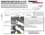
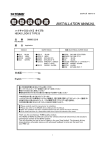
INSTRUCTION
SHEET FOR SET #7.3115
Read this instruction sheet thoroughly before initiating any work!
On rear hub, remove 1-7/16” nut. Remove lower ball joint nut and break loose ball joint only.
Remove 14mm bolts and remove caliper.(4)
Remove 17 & 19mm rear toe link (1) bolts and remove link. BE SURE TO SCRIBE LINES on adjusting bolt
for estimated realignment upon re-assembly.
Remove 17mm nut from lower shock position, slide shock off shaft. Leave shock attached at top.
Remove 19mm bolts, slide upper rear arm (2) down shock and remove.
Remove 19mm bolts and remove upper front arm (3) Remove spindle assembly.
Remove 19mm bolts from rear lower control arm (5). Remove arm.
Using a press, remove bushings from upper front arm (3), upper rear arm (2), rear toe link (1), and two
positions (6,7) on spindle. (HICAS models will not use bushings at positions (9) and (10).
Bushing Removal: The following requires time and patience! For the lower control arm positions and the
one position on the spindle (8), use heat to remove inner metal sleeve. Then, CAREFULLY, use a
hacksaw and cut through the outer metal shell ONLY, this will remove the preload on the shell. Now,
using a punch and hammer, you can remove the shell.
Bushing Installation: Make sure there are no rough edges, apply grease to bushings, sleeves, and ID’s of
arms and spindle. Press in bushings first, then press in sleeves. See parts list for locations.
Installation is reverse of removal. Tighten all bolts to factory specifications.
7
R
1131 VIA CALLEJON, SAN CLEMENTE, CA 92673
C 2003 Energy Suspension. All rights reserved.
May not be reproduced, in any form, or by any means,
Updated
13/DEC/01
BRH
without the written
consent
of Energy
Suspension.
PARTS LIST:
Lower Control Arm (5)
4 - 8310 Control arm bushings
4 - 15.10.155.39 Sleeves (0.750”x0.480”x1.760”)
Other arms (1,2,3)
12 - 8309 Upper & toe link arm bushings
12 - 15.10.518.39 Sleeves (0.875”x0.500”x1.565”)
3
9
2
1
10
8
6
5
090403
4
17395
It is recommended that if you are unfamiliar with this type of work that you refer to a qualified service center specializing in this
type of work. It is also recommended that if you choose to do this work yourself that a factory service manual be obtained for
the proper procedures pertaining to removal, replacement and proper torque specifications for your vehicle. This instruction set
is intended as a guideline for the safe installation of Energy Suspension’s Polyurethane.