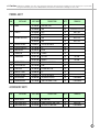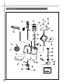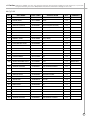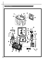
1
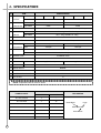
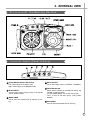
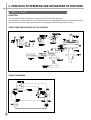
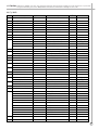
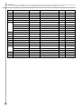
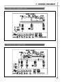
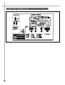
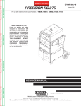
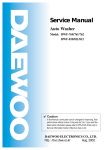
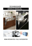
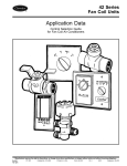
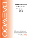
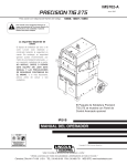
S/M No.:DWM161011
Service Manual
Washing Machine
Model : DW-1050
DW-1051
• Caution:
In this Manual, some parts can be changed for improving,
their performance without notice in the parts list. So, if you
need the latest parts information, please refer to PPL(Parts
Price List) in Service Information Center (http://svc.dwe.co.kr).
Sep. 2001
ASHER AUTO WASHER AUTO WASHER AUTO WASHER AUTO WASHER AUTO WASHER AUTO WASHER AUTO WASHER AUTO WASHER AUTO WASH
TO WASHER AUTO WASHER AUTO WASHER AUTO WASHER AUTO WASHER AUTO WASHER AUTO WASHER AUTO WASHER AUTO WASHER AU
ASHER AUTO WASHER AUTO WASHER AUTO WASHER AUTO WASHER AUTO WASHER AUTO WASHER AUTO WASHER AUTO WASHER AUTO WASH
TO WASHER AUTO WASHER AUTO WASHER AUTO WASHER AUTO WASHER AUTO WASHER AUTO WASHER AUTO WASHER AUTO WASHER AU
ASHER AUTO WASHER AUTO WASHER AUTO WASHER AUTO WASHER AUTO WASHER AUTO WASHER AUTO WASHER AUTO WASHER AUTO WASH
TO WASHER AUTO WASHER AUTO WASHER AUTO WASHER AUTO WASHER AUTO WASHER AUTO WASHER AUTO WASHER AUTO WASHER AU
ASHER AUTO WASHER AUTO WASHER AUTO WASHER AUTO WASHER AUTO WASHER AUTO WASHER AUTO WASHER AUTO WASHER AUTO WASH
WASHING MACHINE
Contents
1. SPECIFICATIONS ..................................................................................................... 2
2. EXTERNAL VIEW ..................................................................................................... 3
3. PRINCIPLES OF OPERATION AND EXPLANATION OF FUNCTIONS ................ 4
4. DIRECTION FOR DISASSEMBLY AND ASSEMBLY ..............................................8
5. TROUBLESHOOTING GUIDE.................................................................................11
6. EXPLODED VIEW AND PARTS LIST.....................................................................16
7. WIRING DIAGRAM ..................................................................................................23
1. SPECIFICATIONS
NO.
ITEM
1 POWER
SOURCE
2 POWER
CONSUMPTION
VOLTAGE
SPECIFICATIONS
AC 110V
AC 220V
WEIGHT
50Hz
PUMP
580W
550W
NON PUMP
530W
500W
PUMP
NET : 35kg, PACKED UP : 37kg
NON PUMP
NET : 34kg, PACKED UP : 36kg
STRONG, NORMAL
HIGH:80l, MEDIUM:70l, LOW:60l
7 REVOLUTION WASH
SPIN
100 rpm
100 rpm
1700 rpm
1400 rpm
WASH
MAX. 15 min., Manual operation
SPIN
MAX. 5 min., Manual operation
9 WASHER TYPE
PULSATOR TYPE
10 SPIN TYPE
CENTRIFUGALLY SEPARATED TYPE
11 MAXIMUM MASS WASH
OF TEXTILE
AC 240V
NET : 884X542X1020, PACKED UP : 898X558X1035 (WXDXH)
6 WATER LEVEL
8 TIMER
AC 220V
60Hz
5 WASHING COURSE
PER MINUTE
AC 110/220V
FREQUENCY
3 DIMENSION
4 MACHINE
AC 127/220V
8.0 kg (DWM-160C)
10.0 kg (DWM-170C)
SPIN
7.0 kg
12 WATER SUPPLY
MANUAL
13 SPIN RINSE
O
14 OUTLET OF DRAIN HOSE
REAR
15 LINT FILTER
O
NOTE : Explanation table for suffix of names.
SUFFIX
POWER SOURCE
2
NON PUMP
PUMP
AC 100V 50/60Hz
J
-
AC 110V 60Hz
T
TP
AC220V 50Hz
N
NP
AC 220V 60Hz
L
LP
AC 240V 50Hz
M
MP
AC 110/220V 50Hz
D
-
AC 127/220V 60Hz
S
-
EXPLANATION
Model Name
Pump
DWM-XXXX N P
Power Source
2. EXTERNAL VIEW
Structure Of The Washing Machine
Control Panel (Panel b Ass’y)
1 LEVER WATER SUPPLY SELECTOR
Left : water supply in the WASH TUB.
Right : water supply in the BASKET SPIN.
2 INLET WATER
Connect inlet hose to supply water in the WASH
TUB or BASKET SPIN.
3 WASH TIMER
Use to select the desired time for washing or rinsing.
4 WASH ACTION
Use to select wash action. (“STRONG”, “NORMAL”)
5 VALVE SELECTOR
Select “WASH, RINSE” for washing and rinsing, and
“DRAIN” to drain the water.
(In case PUMP MODEL turn on the drain pump)
“OFF” to turn off the drain pump. (Only PUMP
MODEL)
6 SPIN TIMER
Used to select the desired time for spinning.
3
3. PRINCIPLES OF OPERATION AND EXPLANATION OF FUNCTIONS
Wash Timer
FUNCTION
The main switch remains ON during the washing time set by turning the timer knob.
At the same time, the internal switch T1 and T2 which provide power to WASH MOTOR alternately at assigned Intervals.
Select switch knob sets the wash type by means of controlling the interval of internal switch contact.
STRUCTURE AND PRINCIPLE OF ACTIVATION
CIRCUIT DIAGRAM
4
Spin Timer
FUNCTION
The spin timer is the switch providing power to the SPIN MOTOR(DRAIN PUMP MOTOR) during the set spin dry
time, and is a spring-type time switch comes on turning and those contact points comes off after the set time.
STRUCTURE AND PRINCIPLE OF ACTIVATION
1) The main shaft turns due to the unwinding force when the spin timer is turned, the spring wound with that force
being delivered through each gear and the spring slowly unwinding at a speed finally controlled by the angle
assembly.
2) The contact point Turns ON and the assembly angle is set in motion which is in the CAM groove in the OFF
state, comes off the groove when the main shaft is turned to wind the spring. The contact point turns OFF,
return to CAM groove when the spring unwind completely.
SAFETY DEVICE FOR BASKET SPIN
The BASKET SPIN is an apparatus which eliminates the water from the laundry through centrifugal separation
generated by rapid revolution(approximately 1,700rpm for 60Hz). Accordingly, there are a DOOR SWITCH to cut
off the power going into the DOOR SPIN is opened and a brake system to stop the rotating BASKET SPIN.
DOOR SWITCH
When the DOOR SPIN is opened during spinning, the DOOR
SWITCH LEVER which sites atopt the DOOR SPIN falls off the
contact, and cuts off the power going into the SPIN MOTOR.
5
BRAKE SYSTEM
When the DOOR SPIN is opened, LINK BRAKE which connect to DOOR SPIN loosens. And then the BRAKE BAND
touches the DRUM COUPLING assembly and stops the BASKET SPIN as it is pulled by the SPRING in the BRAKE FIX
PLATE assembly.
LINK BRAKE
BASKET SPIN
LINK WIRE
BRAKE BAND GAP CONTROL METHOD
The BAND BRAKE works best when the gap between it and
the DRUM COUPLING is about 2mm when the DOOR SPIN
is closed. The BASKET SPIN stops slowly if the gap between
the two is too narrow, the BASKET SPIN revolution is affected
and the PLATE CONTROL WIRE may be adjusted to maintain the BRAKE BAND gap adequately.
BRAKE WIRE
(INNER WIRE)
WASH DECELERATOR ASSEMBLY
The initial deceleration following the activation of the WASH MOTOR takes place through the PULLEY MOTOR
and PULLEY PULSATOR, and the secondary deceleration is done by the gear in the GEAR HOUSING which also
increases their revolution strength. This revolution speed and strength is delivered to the PULSATOR, which is
then able to cause water current that is strong yet soft so that wash loads are not damaged.
MOTOR WASH
About 1,700rpm(60Hz)
1,400rpm(50Hz)
DWM-170C
DWM-160C
PULLEY PULSATOR PULLEY PULSATOR
About 600rpm(60Hz) About 330rpm(60Hz)
600rpm(50Hz)
330rpm(50Hz)
PULSATOR
About 100rpm(60Hz)
100rpm(50Hz)
6
DWM-160C
GEAR HOUSING ASS’Y
The GRAR HOUSING ASSEMBLY is a transmission device which turns the PULSATOR at 3.3:1 (DWM-160C) or
6:1 (DWM-170C) lowered speed through the gear unit assembly which receives power at the GEAR SHAFT UNIT.
STRUCTURE (DWM-160C)
DWM-170C
1) The two sides of the GEAR SHAFT UNIT are supported by the
OILLESS BEARING in the GEAR HOUSING ASSEMBLY.
2) The GEAR UNIT ASSEMBLY is connected to the GEAR
SHAFT 1 and GEAR SHAFT UNIT by the GEAR and GEAR
UNIT respectively.
3) The two sides of GEAR SHAFT 1 are supported by the OIL
SEAL and OILLESS BEARING in the GEAR HOUSING
ASSEMBLY.
STRUCTURE (DWM-170C)
BELLOWS ASS’Y
The wrinkled rubber device on the botton of the BASKET SPIN is
called BELLOWS ASSEMBLY.
It has a waterseal and a oilless metal inside to prevent leakage and so that the BASKET SPIN may work smoothly.
Filter
Much lint may be obtained depending upon the kind of clothes to
be washed and same of the lint may also be suck to the clothes.
To minimize this possibility, a lint filter is provide on the upper part
of the FILTER OVERFLOW to filter the wash water.
Use of the lint filter during every wash is recommend.
CLEANING THE LINT FILTER
1) Remove the FILTER AS from the FILTER OVERFLOW by
pressing it downwards.
2) Turn the FILTER AS inside out, and wash the lint off with water.
3) Return the FILTER AS it was, and fix the FILTER AS to the FILTER OVERFLOW.
7
4. DIRECTION FOR DISASSEMBLY AND ASSEMBLY
Ass’y Panel Back
1. Remove 3 screws on the PANEL B.
2. Remove KNOB, wash timer and spin timer on the
PANEL B.
3. Remove 3 screws and CONTROL LEVER
Basket Spin
4. Remove 4 screws on the COVER BACK.
8
5. Separate LINK BRAKE and ASSEMBLY BRAKE
WIRE.
6. Remove 1 bolt and nut on the upper side of the
DRUM COUPLING AS.
7. Remove the PLATE T on the TUB.
8. Lift up the BASKET SPIN.
Ass’y Base Under
9. Remove 1 screw on the CABINET.
10. Separate HARNESS AS connectors.
9
10
11. Remove a V-BELT from PULLEY MOTOR.
12. Turn over the washing machine.
13. Remove 7 screws on the BASE UNDER ASSY.
14. Remove 3 screws on the BRACKET MOTOR, and
remove the SPIN MOTOR.
15. Remove 3 bolts on the BASE UNDER, and
remove the WASH MOTOR.
16. Remove 1 screw on the FIXTURE PUMP. (In case
of pump model)
5. TROUBLESHOOTING GUIDE
NOTES
Pull out the power plug to repair and make sure that the Washing Machine has been properly
grounded.
Concerning Wash
PROBLEM
CHECK POINT
CAUSE
Is the Power properly connected?
NO
SOLUTION
Reconnect the Power Cord.
YES
Is there a whirring sound from the
Wash Motor when turned on?
YES
NO
Is the Condeser properly connected?
Pulsator
does not
rotate.
Motor does not start due to
opening the Condenser circuit
Reconnect the Condenser.
Power has been cut off by
the Thermal Protector.
Wash restart when Motor
cools.
Improper wiring
Reconnect the wiring
Defective Wash Timer
Replace Wash Timer
Defective Wash Motor
Replace Wash Motor
The wash load is more
than 8.0kg (160C) or
10.0kg (170C)
Reload with proper wash
load.
Defect of mechanical
assembly
Tighten the screws fixed on
the Pulleys.
Worn out V-Belt
Replace V-Belt
Revolution obstructed by
impurities
Remove impurities after
disassembling pulsator.
NO
YES
Is the Motor hot?
(In case there is Thermal Protector)
NO
NO
Is the Wiring good?
(Refer to the Wiring Diagram)
YES
NO
Is the contact of Wash Timer good?
YES
Is the Wash Load appropriate?
NO
YES
NO
Pulsator
does not
rotate
smoothly.
Are the Pulsator and Motor
Pulleys securely assembled?
YES
Does the V-Belt slip?
YES
YES
YES
Are there impurities between the
Pulsator.
NO
11
PROBLEM
CHECK POINT
CAUSE
SOLUTION
YES
Pulsator
does not
rotate
smoothly.
Does the Gear Housing Shaft
rotate properly when the Pulsator
has been disassembled?
NO
NO
Is the wiring of Wash condenser
properly connected?
Pulsator. only
rotates in one
direction.
Worn out the Serration
within the Pulsator.
Replace Pulsator.
Defective Gear Housing
Replace Gear Housing As.
Improper Connection
Reconnect
Improperly Wiring
Reconnect the Wash
Timer.
Defective Wash timer
Replace Wash Timer.
Impurites between Pulsator
and tub
Remove impurities after disassembling Pulsator.
YES
NO
Is the wiring of Wash Timer properly connected?
YES
YES
Are there strange noise from Tub
when the Pulsator rotate?
NO
NO
There is
excessive
noise during
Washing
Pulsator improperly
assembled.
Tighten the Pulsator fixing
screw.
Something is in contact with
the Pulsator Pulley or Motor
Pulley or other rotating parts.
Adjust the parts so that
there are no impurities in
contact with rotating parts
CAUSE
SOLUTION
The contact Door Switch is
open.
Keep the Door Spin closed
during spin.
Concerning Spin
PROBLEM
CHECK POINT
Is the Door Spin open?
NO
The Basket
Spin does
not rotate.
Is there a whirring sound from the
Spin Motor when turned ON?
NO
12
YES
YES
PROBLEM
CHECK POINT
CAUSE
SOLUTION
YES
Brake wire is too long.
The Brake Band is touching
the Drum Coupling Assembly.
Assemble after loosening
LINK BRAKE and adjusting
downward.
NO
BRAKE SPRING is broken.
Replace Brake Spring.
Power has been cut off by
the Thermal Protector
Power restored when motor
cools.
Improper wiring
Reconnect wiring
Defective connection
Replace Door Switch or
reshape the Lever.
Improper wiring
Reconnect the terminal.
Defective Spin Timer
Replace the Spin Timer.
Defective Spin Motor
Replace the Spin Motor.
Basket Spin does not balanced
due to wash load.
Reload the clothes so they
are well balanced
Basket Spin does not balanced
due to wash load.
Reload the clothes and
press down the Safety
Cover into Basket Spin.
Improper structural assembly
Tighten the Bolt Drum
Coupling Assembly.
Basket Spin unbalance
Replace Basket Spin.
The Waterseal or the oilless metal in the Bellows
Assembly worn out.
Replace Bellows Assembly.
NO
YES
Is the Motor hot? (In case there is
Thermal Protector)
NO
The Basket
Spin does
not rotate.
NO
Is the wiring good? (Refer to
Wiring Diagram)
YES
NO
Is the Door Switch Lever properly
placed on the Door Spin?
YES
YES
Is the Door Switch terminal properly connected?
YES
NO
Is the Contact of Spin Timer good?
YES
NO
Is the wash load well balanced?
YES
Are clothes or the Safety Cover
stick out from Basket Spin?
There are
strange
noise and
servere
vibration
during spinning.
NO
YES
YES
Is the assembly between the
Drum Coupling Assembly and
Spin Motor or Basket Spin loose?
NO
Is the Basket Spin itself well balanced?
NO
YES
13
PROBLEM
CHECK POINT
CAUSE
SOLUTION
NO
Is the Bellows Assembly properly
assembled?
There is leakage during
spinning.
Re-assemble
Bellows Assembly.
The Waterseal or the
Oilless Metal in the Bellows
Assembly is worn out.
Replace Bellows
Assembly.
YES
NO
The Brake Band touches the
Drum Coupling when the Door
Spin open.
YES
Basket Spin
does not
stop with the
Door Spin
open
Waterproofing not working
due to defective assembly.
Is the electric connection of the
Door Switch good?
NO
YES
Brake wire is too short.
Replace after loosening
LINK BRAKE and adjusting
upward.
Brake Band is worn out.
Replace Brake Band or
Brake Fix Assembly.
Defective
Door Switch
Replace
Door Switch
The contact of the Door
Switch does not open due
to deformity of the lever of
Door Switch.
Replace Door Switch or
reshape the lever of Door
Switch.
Concerning Drainage (Pump)
PROBLEM
CHECK POINT
Is the height of the drainage area where
the Drain Hose hangs over 1m?
CAUSE
YES
SOLUTION
Hang the Drain Hose lower.
The Drain Hose is too high.
NO
YES
Are there impurities on the Drain
Strainer?
Drainage is
not satisfactory
Impurities are obstructing
drainage.
Remove out impurities on
the drain Strainer
Impurities are obstructing
drainage.
Remove impurities or
replace Valve Housing or
Inlet Joint.
Impurities are blocking the
Drain Hose
Remove impurities
NO
YES
Are there impurities in the Valve
Housing or Inlet Joint?
NO
14
PROBLEM
Draining
does not
function during drain
selecting
CHECK POINT
CAUSE
Is the Drain Selector in the DRAIN
position
YES
The position is fault.
Turn the Drain Selector to
DRAIN.
Defective wiring
Reconnect wiring
Defective Pump motor
Replace Pump Motor
NO
NO
Is the pump Motor wiring properly
connected?
YES
Are the wiring of the Spin Timer
and the Pump Motor good?
Drain does
not function
during
Spinning.
SOLUTION
NO Defective wiring
Reconnect wiring
NO
Is the Spin Timer’s contact good?
Defective Spin Timer
Replace Spin Timer
Defective Pump motor
Replace Pump Motor
YES
Concerning Drainage (Non Pump)
PROBLEM
CHECK POINT
CAUSE
SOLUTION
Impurities are obstructing
drainage.
Remove impurities on the Drain
Strainer
Impurities are obstructing
drainage.
Remove impurities or replace
Valve Housing or Inlet Joint
Impurities are blocking the
Drain Hose
Remove impurities
Mismanupilation
Turn Drain Selector to
WASH/RINSE position
There are impurities
between the Valve Housing
and Valve Bellows.
Remove impurities and
replace Valve Housing.
YES
Are there impurities on the Drain
Strainer?
NO
Drainage is
not satisfactory.
YES
Are there impurities in the Valve
Housing or Inlet Joint?
NO
YES
Is the Drain Selector on the operation Panel at the DRAIN position?
Water keeps
draining during wash
NO
15
6. EXPLODE VIEW AND P ARTS LIST
ASS'Y PANEL BACK
16
✔ Caution: In this Service Manual, some parts can be changed for improving, their performance without notice in the parts list. So, if you need the
latest parts information, please refer to PPL(Parts Price List) in Service information Center(http://svc.dwe.co.kr)
PANNEL ASS'Y
NO.
1
2
3
PART NAME
KNOB
PANEL B
DECORATOR PANEL
PART CODE
DESCRIPTION
QTT'Y
REMARKS
3613403800
DWM-160C, ABS
4.0
3613404000
ABS
4.0
161C/162C/171C/172C
3614239000
HIPS
1.0
160C/170C
3614274300
HIPS
1.0
161C/162C/171C/172C
3611621800
ABS
1.0
161C/171C
3611621810
ABS
1.0
162C/172C
4
SCREW TAPPING
7122401411
T2S TRS 4X14 MFZN
3.0
5
LEVER W.S SELECT
3613702300
PP
1.0
6
HOSE SPRAY
3613201201
PE-LD
1.0
7
TIMER SPIN
3619911200
S-160CA
1.0
8
TIMER WASH
3619911100
S-DT15NT
1.0
OPTION
3619911300
S-K16NT
1.0
OPTION
9
SWITCH DRAIN
3619043700
VP531A-2H,250VAC/15A
1.0
10
LEVER CONTROL
3613701400
POM
2.0
11
LINK VALVE
3617804200
PP BAND W6 L=784
1.0
12
BRACKET PANEL
3610606200
PP
1.0
13
SCREW TAPPING
7122401411
T2S TRS 4X14 MFZN
3.0
14
SWITCH DRAIN
3619045300
VO, SZM-V15-18FA-91
1.0
PUMP MODEL
15
HARNESS DRAIN
3612790600
160CP SW DRAIN L=1100
1.0
PUMP MODEL
ACCESSORY ASS'Y
NO.
PART NAME
PART CODE
DESCRIPTION
QTT'Y
REMARKS
1
COVER SAFETY
3611419900
LDPE(DIA:286)
1.0
2
HOSE DRAIN O AS
3613224310
820MM, HANGER, NON CLAMP
1.0
NON PUMP
3
HOSE DRAIN O AS
3613218800
LD-PE/EVA L=1600 PUMP
1.0
PUMP MODEL
17
Ass’y Tub
18
✔ Caution: In this Service Manual, some parts can be changed for improving, their performance without notice in the parts list. So, if you need the
latest parts information, please refer to PPL(Parts Price List) in Service information Center(http://svc.dwe.co.kr)
ass’y tub
NO.
PART NAME
PART CORD
SPECIFICATION
Q’TY
REMARKS
1
TUB
3618819000
PP
1.0
2
DOOR WASH
3611799600
HIPS
1.0
3
PULSATOR AS
3619706800
DWM-160C
1.0
4
SPECIAL SCREW
3616002901
SUS 304(NON SLOCK)
1.0
5
BASE WATER SUPPLY
3610390900
PP
1.0
6
FILTER OVERFLOW AS
3611903800
WITH FILTER AS
2.0
7
BALANCER AS
3616105800
DWM-160C
1.0
8
SCREW TAPPING
7122401211
T2S TRS 4*12 MFZN
4.0
9
BASKET SPIN
3619103600
PP(J-360A)
1.0
10
BELLOWS
3616402000
NBR
1.0
11
FIXTURE BELLOWS
3612005800
PP
1.0
12
LINK BRAKE
3617804300
PP BAND W6 L=564
1.0
13
SPRING COVER
3615108810
HSW3
1.0
14
DOOR SPIN
3611799500
HIPS
1.0
15
PLATE T
3614525200
PP
1.0
16
COVER INNER
3611419700
PP
1.0
17
RING O
4506H05050
CR
1.0
18
GEAR HOUSING ASS'Y
3617306201
3.3:1
1.0
DWM-160C
3617309100
6:1
1.0
DWM-170C
19
SCREW TAPPING
7122502011
T2S TRS 5X20 MFZN
5.0
20
PULLEY PULSATOR
3618432500
FRPP
1.0
DWM-160C
3618432600
FRPP
1.0
DWM-170C
21
SPECIAL BOLT
3616008400
M6 SIDE-FIXING
1.0
22
PROTECTOR F.B
3618303500
NBR
1.0
23
VALVE CAP
4505F06013
PE-HD
1.0
24
SPRING VALVE
4505C06022
SWC WR 1.0D
1.0
25
ROD VALVE
3618504000
PP
1.0
26
BELLOWS VALVE
4505C06041
NBR
1.0
27
INLET JOINT
3617504100
PP
1.0
28
CASE VALVE
3611131600
PP
1.0
29
COVER S/W AS
4507K44031
15A 220VAC 1006FD
1.0
30
SCREW TAPPING
7122502011
T2S TRS 4X14 MFZN
1.0
19
Ass’y Main
20
✔ Caution: In this Service Manual, some parts can be changed for improving, their performance without notice in the parts list. So, if you need the
latest parts information, please refer to PPL(Parts Price List) in Service information Center(http://svc.dwe.co.kr)
ass’y main
NO.
PART NAME
PART CORD
1
ASSY CABINET
PRCACA6200
2
PLATE UPPER
3614525100
3
SCREW TAPPING
4
COVER BACK
5
SCREW TAPPING
6
SPECIFICATION
Q’TY
REMARKS
DWM-160C 0.6T
1.0
SGCC 0.6T
1.0
7122401011
T2S TRS 4*10 MFZN
4.0
3611419800
SECC 0.4T
1.0
7112400811
T1 TRS 4*8 MFZN
4.0
BASE UNDER
3610390800
PP
1.0
7
SCREW TAPPING
7122401011
T2S TRS 4*10 MFZN
7.0
8
CUSHION SPOT
450M712010
PP
1.0
9
CUSHION MOTOR
450M712020
NR
3.0
10
MOTOR WASH
3618961900
220~240V/50HZ,W1S35VD060
1.0
N(P), M(P)
3618961600
110V/60HZ,W1S35ED060
1.0
T(P)
3618961800
220V/60HZ,W1S35UD060
1.0
L
D,S
3618962000
W1S35GD060
1.0
11
SPECIAL SCREW
3616003100
M5X35 WASHER
3.0
12
PULLEY MOTOR AS
3618431700
PRESS(SGCC1.2T,D31),2.1MM
1.0
50HZ
PULLEY MOTOR AS
3618431600
PRESS(SGCC1.2T,D24),4.3MM
1.0
60HZ
13
WASHER PLAIN
7400108411
PW-1-8.4 MFZN
1.0
14
WASHER SPRING
7401008011
SW-8 MFZN
1.0
15
NUT HEX
7392800011
M8*P1.25 MFZN
1.0
16
BELT V
450M700020
M-32
1.0
DWM-160C
3616590700
M-24
1.0
DWM-170C
AC 220~240V, 50HZ,PLASET
1.0
NP, MP
TP
17
UNIT DRAIN PUMP AS
3618964800
3618964900
AC 110V, 60HZ,PLASET
1.0
18
FIXTURE PUMP
3612005700
PP
1.0
19
SCREW TAPPING
7112402011
T1 TRS 4X20 MFZN
1.0
20
UNIT CAPACITOR
3618948200
9.7/5.2 400/440 CON-4P
1.0
L,N(P),M(P)
3618948600
45.6/25 200/200 CON-4P
1.0
T(P)
21
CAPACITOR WASH
4505E11000
25+25UF
1.0
D, DUAL
4509C11020
200V 20.8UF*2
1.0
S, DUAL
22
CAPACITOR SPIN
4509C11010
MF CAPACITOR 200V 20.8MF
1.0
D,S,DUAL
23
HARNESS CONDENSER
3612706710
CONN A,B
1.0
DUAL
24
CORD POWER AS
3611332100
T VACTFK 2*0.75 2.3M GY
1.0
3611331700
A VACTFK 2*0.75 2.3M GY
3611331310
VCTF 3*0.75 2.3M GY
1.0
1.0
3611331630
H05VV-F 3*0.75 WH
1.0
3611331650
H05VV-F 3*0.75 BK
1.0
3611331110
VCTF 3*0.75 2.3M GY
1.0
3611331810
H05VV-F 3*0.75 2.3M BK
1.0
3611332100
VCTFK 2*0.75 2.3M GY
1.0
3611331930
C SJT 3*18AWG 2.3M GY
1.0
3611331700
A VCTFK 2*0.75 2.3M GY
1.0
3611331700
FH05VV 3*0.75 2.3M BK
1.0
25
COUPLING DRUM AS
3617002100
DWM-160C
1.0
26
SPECIAL BOLT AS
3616008000
6B-1-M8X12
2.0
21
✔ Caution: In this Service Manual, some parts can be changed for improving, their performance without notice in the parts list. So, if you need the
latest parts information, please refer to PPL(Parts Price List) in Service information Center(http://svc.dwe.co.kr)
NO.
22
PART NAME
PART CORD
SPECIFICATION
Q’TY
REMARKS
27
BRAKE FIX PLT AS
4505C54000
2-WAY
1.0
28
BOLT HEX
7341500811
6B-1-5X8 MFZN
3.0
29
SPRING BRAKE
4507K53010
SWC D1.0 ZN8-C
1.0
30
ASS'Y BRAKE WIRE
3619201702
SUS WIRE+PE L260
1.0
31
BOLT HEX
7341501611
6B-1-5X16 HS MFZN
3.0
32
UNIT SPIN MOTOR
3618949601
110V 60HZ W1D35EF001
1.0
T(P)
3618949201
220V 60HZ W1D35UF001
1.0
L
3618949401
220-240V 50HZ W1D35VF001
1.0
N(P), M(P)
3618950101
W1D35FF002 110/220V 50HZ
1.0
D, DUAL
3618950001
W1D35LF002 120/240V 60HZ
1.0
S, DUAL
33
CUSHION MOTOR SPIN
3611556300
PP
3.0
34
BRACKET MOTOR SPIN
3610606100
SPG 1.6T
1.0
35
SCREW TAPPING
7122502511
T2 TRS 5X25 MFZN
3.0
36
SPRING CUSHION
3615112700
SWC D=3.2
1.0
37
STOPPER
4506H14020
PE - HD
1.0
38
STOPPER LOWER
3615200800
PP
1.0
39
RUBBER DAMPING
4506H14030
NBR
1.0
40
HARNESS ASS'Y
3612757300
7510
1.0
PUMP MODEL
3612757220
800C
1.0
N,M,T,L
3612756301
7510
1.0
D,S
41
HARNESS EARTH
3612757810
UL1015 AWG18 490
1.0
42
CABLE CLAMP
3611202610
NYLON66 DA-5N
1.0
43
TAPTITE SCREW
7272400811
TT3 TRS 4*8 MFZN
1.0
7. WIRING DIAGRAM
Single Voltage/Normal
Single Voltage/Pump
23
Dual Voltage/Normal
24
DAEWOO ELECTRONICS CO., LTD.
686, AHYEON-DONG MAPO-GU SEOUL, KOREA
C.P.O. BOX 8003 SEOUL, KOREA
TELEX: DWELEC K28177-8
CABLE: “DAEWOOELEC”
FAX: 82-2-360-7877
TEL: 82-2-360-7114
http://www.dwe.co.kr
S/M NO. : DWM161C011
PRINTED DATE: SEP.2001