1
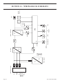
SERVICE MANUAL FOR
INDUCTION COOKERS WITH
RTCS TECHNOLOGY
(REAL TIME TEMPERATURE CONTROL SYSTEM)
COUNTER TOP/BUILT IN/WOK MODELS
IMPORTANT NOTE:
INDUCTION COOKERS MANUFACTURED WITH RTCS TECHNOLOGY WILL HAVE
FIVE DIGITS IN THE CENTER OF THE SERIAL NUMBER
EXAMPLE: BA06.00001.0505
MODELS
GIU 1.5 (BH/BA 1500)
GIU 1.8 (BH/BA 1800)
GIU 2.5 (BH/BA 2500)
GIU 3.5 (SH/BA 3500)
GIU 5.0 (SH/BA 5000)
GIU 2.5 BI (BH/IN 2500)
GIU 3.5 BI (SH/IN 3500)
GIU 5.0 BI (SH/IN 5000)
GIWOK 3.5 (SH/WO 3500)
GIWOK 5.0 (SH/WO 5000)
GIWOK 3.5 BI (SH/WO/IN 3500)
GIWOK 5.0 BI (SH/WO/IN 5000)
NITATION
SA
C
LIS T E D
CM
86037
Continuous product improvement is a Garland policy, therefore design and specifications are subject to change without notice.
GARLAND COMMERCIAL INDUSTRIES
185 East South Street
Freeland, Pennsylvania 18224
Phone: (570) 636-1000
Fax: (570) 636-3903
Part
Part##4521635
4521635(07/06)
(07/06)
GARLAND COMMERCIAL RANGES,
LTD.
1177 Kamato Road, Mississauga, Ontario L4W 1X4
CANADA
Phone: 905-624-0260
Fax: 905-624-5669
Enodis UK LTD.
Swallowfield Way, Hayes, Middlesex UB3 1DQ ENGLAND
Telephone: 081-561-0433
Fax: 081-848-0041
© 2006 Garland Commercial Industries,Page
Inc.
TABLE OF CONTENTS
SECTION 1 –SAFETY . . . . . . . . . . . . . . . . . . . . . . . . . . . . . . . . . . . . . . . . . . . . . 3
Description Of Warning Signs . . . . . . . . . . . . . . . . . . . . . . . . . . . . . . . . . . . . . . . . . . . . . . . . . . . 3
Personnel Qualification And Training . . . . . . . . . . . . . . . . . . . . . . . . . . . . . . . . . . . . . . . . . . . . . 3
Safety Information, Installation And Service . . . . . . . . . . . . . . . . . . . . . . . . . . . . . . . . . . . . . . . . 3
Unauthorized Reconstruction And Use Of Spare Parts . . . . . . . . . . . . . . . . . . . . . . . . . . . . . . . . 3
Improper Operating Methods . . . . . . . . . . . . . . . . . . . . . . . . . . . . . . . . . . . . . . . . . . . . . . . . . . . 3
SECTION 2 – TECHNICAL INFORMATION . . . . . . . . . . . . . . . . . . . . . . . . . 4
SECTION 3 – OPERATION . . . . . . . . . . . . . . . . . . . . . . . . . . . . . . . . . . . . . . . . . 5
Adjusting The Performance Rate . . . . . . . . . . . . . . . . . . . . . . . . . . . . . . . . . . . . . . . . . . . . . . . . . 5
Temperature Check . . . . . . . . . . . . . . . . . . . . . . . . . . . . . . . . . . . . . . . . . . . . . . . . . . . . . . . . . . . 5
Protection Overload Current . . . . . . . . . . . . . . . . . . . . . . . . . . . . . . . . . . . . . . . . . . . . . . . . . . . . 5
SECTION 4 – TESTS . . . . . . . . . . . . . . . . . . . . . . . . . . . . . . . . . . . . . . . . . . . . . . 6
Pan Material For Induction Cookers . . . . . . . . . . . . . . . . . . . . . . . . . . . . . . . . . . . . . . . . . . . . . . 6
Pan Detection . . . . . . . . . . . . . . . . . . . . . . . . . . . . . . . . . . . . . . . . . . . . . . . . . . . . . . . . . . . . . . . 6
Test With Pans . . . . . . . . . . . . . . . . . . . . . . . . . . . . . . . . . . . . . . . . . . . . . . . . . . . . . . . . . . . . 6
Test With Metallic Plates . . . . . . . . . . . . . . . . . . . . . . . . . . . . . . . . . . . . . . . . . . . . . . . . . . . . 6
Power Rating . . . . . . . . . . . . . . . . . . . . . . . . . . . . . . . . . . . . . . . . . . . . . . . . . . . . . . . . . . . . . . . . 7
Fan . . . . . . . . . . . . . . . . . . . . . . . . . . . . . . . . . . . . . . . . . . . . . . . . . . . . . . . . . . . . . . . . . . . . . . . . 7
Test Of The Components . . . . . . . . . . . . . . . . . . . . . . . . . . . . . . . . . . . . . . . . . . . . . . . . . . . . . . . 7
Rectifier . . . . . . . . . . . . . . . . . . . . . . . . . . . . . . . . . . . . . . . . . . . . . . . . . . . . . . . . . . . . . . . . . 7
Transistor module (IGBT) . . . . . . . . . . . . . . . . . . . . . . . . . . . . . . . . . . . . . . . . . . . . . . . . . . . 8
CU (RTCS) Sensors . . . . . . . . . . . . . . . . . . . . . . . . . . . . . . . . . . . . . . . . . . . . . . . . . . . . . . . . 8
Potentiometer . . . . . . . . . . . . . . . . . . . . . . . . . . . . . . . . . . . . . . . . . . . . . . . . . . . . . . . . . . . . . 8
SECTION 5 – MAINTENANCE/SERVICE . . . . . . . . . . . . . . . . . . . . . . . . . . . . 9
SECTION 6 – FAULT FINDING . . . . . . . . . . . . . . . . . . . . . . . . . . . . . . . . . . . . 12
General Information . . . . . . . . . . . . . . . . . . . . . . . . . . . . . . . . . . . . . . . . . . . . . . . . . . . . . . . . . 12
Error Messages . . . . . . . . . . . . . . . . . . . . . . . . . . . . . . . . . . . . . . . . . . . . . . . . . . . . . . . . . . . . . . 12
Flow chart to fault finding . . . . . . . . . . . . . . . . . . . . . . . . . . . . . . . . . . . . . . . . . . . . . . . . . . . . . 14
SECTION 7 – EXCHANGE OF SPARE PARTS . . . . . . . . . . . . . . . . . . . . . . . . . 15
To Open The Induction Unit (Counter Top Models) . . . . . . . . . . . . . . . . . . . . . . . . . . . . . . . . . 15
To Open The Induction Unit (Built In Models) . . . . . . . . . . . . . . . . . . . . . . . . . . . . . . . . . . . . . 15
SECTION 8 – ADJUSTMENT OF PROCESS PARAMETERS . . . . . . . . . . . . . 15
Initializing CU Sensors By The Short Circuit Plug . . . . . . . . . . . . . . . . . . . . . . . . . . . . . . . . . . .
Initializing The Induction Unit By PC Or Laptop . . . . . . . . . . . . . . . . . . . . . . . . . . . . . . . . . . .
Change Of The Parameters . . . . . . . . . . . . . . . . . . . . . . . . . . . . . . . . . . . . . . . . . . . . . . . . . . . .
Parameters For (Mains) Power Current And Pan Detector . . . . . . . . . . . . . . . . . . . . . . . . . . . . .
15
16
16
18
SECTION 9 – IR (INFRARED) INTERFACE . . . . . . . . . . . . . . . . . . . . . . . . . . . 19
SECTION 10 – WIRING BLOCK SCHEMATIC . . . . . . . . . . . . . . . . . . . . . . . 22
Page Part # 4521635 (07/06)
SECTION 1 –SAFETY
Description Of Warning Signs
Identifies safety information about
dangers which may cause serious
personal injury if equipment is not
operated properly
Dangerous voltage warning symbol,
indicates a risk of electric shock and
hazards from dangerous voltage.
CAUTION
Indicates a hazard or unsafe practice
which could result in minor personal
injury or property damage.
Electromagnetic field
Warning signs mounted directly on the cooker must
be observed at all times and kept in a fully legible
condition
Personnel Qualification And Training
All persons involved in assembly, installation,
commissioning, operation and maintenance must have
the appropriate qualifications. The scope of responsibility,
competence and supervision of the staff must be defined
and controlled.
Part # 4521635 (07/06)
Safety Information, Installation And Service
Operators of the equipment must ensure that all
installation, service and as well as all inspections, are
performed by authorized and qualified personnel. Before
attempting to operate the equipment carefully read the
information and instructions outlined in the ”Installations
and Operating” manual. For all installations, service,
maintenance, repair and or overhaul of the induction
cookers, personnel must be specially qualified and must
have attended a technical training course authorized by
Garland.
Do not attempt to perform any repairs or replace any
part of the induction cooker unless, all power supply to
the cooker has been disconnected.
Unauthorized Reconstruction And
Use Of Spare Parts
Reconstruction of the cooker or changes to the cooker
are not allowed. Contact the manufacturer if you intend
to do any changes to the cooker. To guarantee safety,
use only genuine OEM spare parts and accessories,
authorized by the manufacturer. Garland will not be
held liable for any damage or injury caused by used of
other components.
Improper Operating Methods
The operating reliability of the cookers can only be
guaranteed when the cooker is used appropriately.
The limit values stated in this manual must not be
exceeded.
Page SECTION 2 – TECHNICAL INFORMATION
Model BH/BA (Counter models)
120 V/1 Ph
208 V/1 Ph
Wattage kW
1.5/1.8 kW
2.5/3.5 kW
2.5/3.5 kW
12.5/15
12/14.5/17
10/12.5/14.5
Power factor Cos ϕ
>0.95
>0.95
>0.95
Discharge rate mA
4
4
4
190 (7.5”)
190 (7.5”)
190 (7.5”)
Current A
∅ Coil mm
Model BH/IN (Counter Models)
208 V/1 Ph
240 V/1 Ph
2.5 kW
2.5 kW
12
10
Power factor Cos ϕ
>0.95
>0.95
Discharge rate mA
4
4
190 (7.5”)
190 (7.5”)
Wattage kW
Current A
∅ Coil mm
Model SH/BA (Counter Models)
208 V/1 Ph
240 V/1 Ph
Wattage kW
3.5 kW
3.5 kW
5 kW
Current A
max. 16
14.5
max. 16
Power factor Cos ϕ
>0.95
>0.95
>0.95
Discharge rate mA
4
4
4
∅ Coil mm
190 (7.5”)
190 (7.5”)
190 (7.5”)
Model SH/IN (Built in Models)
208 V/1 Ph
240 V/1 Ph
208 V/3 Ph
Wattage kW
3.5 kW
3.5 kW
5 kW
Current A
max. 16
14.5
max. 16
Power factor Cos ϕ
>0.95
>0.95
>0.95
Discharge rate mA
4
4
4
∅ Coil mm
190 (7.5”)
190 (7.5”)
190 (7.5”)
Model SH/WO (Counter Wok Models)
208 V/3 Ph
208 V/1 Ph
240 V/1 Ph
208 V/3 Ph
Wattage kW
3.5 kW
3.5 kW
5 kW
Current A
max. 16
14.5
max. 16
Power factor Cos ϕ
>0.95
>0.95
>0.95
Discharge rate mA
4
4
4
∅ Coil mm
190 (7.5”)
190 (7.5”)
190 (7.5”)
Model SH/WO/IN (Built in Wok Models)
208 V/1 Ph
240 V/1 Ph
208 V/3 Ph
Wattage kW
3.5 kW
3.5 kW
5 kW
Current A
max. 16
14.5
max. 16
Power factor Cos ϕ
>0.95
>0.95
>0.95
Discharge rate mA
4
4
4
190 (7.5”)
190 (7.5”)
190 (7.5”)
∅ Coil mm
Page 240 V/1 Ph
Part # 4521635 (07/06)
Maximum tolerance of power supply
Nominal voltage +6/-10 %
Frequency
50/60 Hz
Protection class
IP X0
Min. diameter of pans
Approx. 12 cm ( 4.7” )
Max. ambient temperature: stockage
-20°C to 70°C (-4°F to 158°F)
Max. ambient temperature: function
-5 °C to 40°C (23°F to 104 °F)
Max. relative humidity of air: stockage
10 to 90 %
Max. relative humidity of air: function
30 to 90 %
SECTION 3 – OPERATION
Adjusting The Performance Rate
Power board
The performance rate is adjusted by the potentiometer
(control knob). The inductive performance depends on
the position of the potentiometer:
The temperature of the power board is checked by a
temperature sensor. As soon as the heat sink is heated over
70°C (158°F), a cooling fan starts. A heat sink temperature
of more than 80°C (176°F) automatically reduces the
power in order to keep the induction cooker working
under normal conditions. The internal temperature of
the unit is supervised as well. The power is reduced by
50% if the temperature reaches 75°C (167°F). As soon
as the temperature reaches 90°C (194°F) the unit stops
working and shows the error code “E06” (See Error
message, Section 6).
• Position 1 = minimum power
• Position 9 (resp. Position 12) = maximum power.
Temperature Check
Induction coil
The temperature of the induction coil is checked by
a temperature sensor. If the coil is heated over the
maximum temperature, the heating process stops. As
soon as the coil has cooled down, the Induction unit
can be re-started. Turn the position of the control knob
to “0” and then to the required power level (See Error
Message, Section 6).
Part # 4521635 (07/06)
Protection Overload Current
When inappropriate pan material or magnetic objects are
detected on the heating area, the current in the induction
coil may raise excessively. In order to protect the power
board, the coil current is checked and as soon as the
current in the coil exceeds the maximum tolerance, the
generator stops and there is no further active energy
exchange. The unit can be re-started as soon as normal
working conditions are reached.
Page SECTION 4 – TESTS
Pan Material For Induction Cookers
When cooking with induction it is very important to use
the appropriate pan material. The bottom of the pan is the
element that closes the magnetic field generated by the
induction coil. We highly recommend only appropriate
induction pans be used with this equipment.
Pan Detection
ATTENTION
The heating area is warmed up
by the hot pan. To avoid injuries
(burns) do not touch the heating
area.
A quick test can be performed to determine if a pan
is appropriate. For this test you will need 1- Liter (34
ounces) of water at a temperature of 20°C (68°F). Heat
up the pan with the cooker set to maximum power and
measure the time it takes for the water to boil. Compare
your time that referenced by Garland: (2.5kW ➔ approx.
240 sec., 3.5kW ➔ approx. 140 sec., 5kW ➔ approx. 80
sec., 8kW ➔ approx. 60 sec.). This heat-up time gives you
information regarding the efficiency of the pan tested.
Bad pans have considerably longer heating-up times for
the same quantity of water.
These tests show whether the induction cooker is
operating correctly when small diameter pans are used
and, when small metallic objects are heated-up on the
heating area.
A magnet can be used to determine whether the pan
material is appropriate for induction cooking. The
magnet must attach its self to the bottom of the pan.
Please note, this magnet test will not determine the
material structure of the pan or its efficiency. In some
cases the magnet will attach itself to the bottom of the
pan however, the pan may not be suitable for use with
induction cooking. Always use pans which are suitable
and designed for induction cooking.
Test With Pans
This test will require the following material:
An appropriate pan with a bottom diameter of 12cm
(4.7”) or two untreated round iron plates, approximately
4mm (0.16”) thick:
• iron plate 1: diameter d = 12 cm (4.7”)
• iron plate 2: diameter d = 7 cm (2.75”)
Step
Action
Level
Result
1
Place the pan in
the middle of the
heating area
1...9 (12) Heat, the
indicator lights
2
Push the pan
until the edge
of the pan is in
the middle of the
heating area
1...9 (12) No heating, the
indicator does not
light
Test With Metallic Plates
Step
Page Action
Level
Result
1
Place the metallic 1...9 (12) Heat, the
plate 1 in the
indicator lights
middle of the
heating area
2
Place the metallic 1...9 (12) No heating, the
plate 2 in the
indicator does not
middle of the
light
heating area
Part # 4521635 (07/06)
Power Rating
ATTENTION
Test Of The Components
The heating area is warmed up
by the hot pan. To avoid injuries
(burns) do not touch the heating
area.
Step
Action
Level
1
Place the pan
on the heating
area until water is
boiling
9 (12)
2
Reduce the
power by turning
slowly the control
knob
1
Place a pan on
the heating area
and fill it up with
1- Liter or (34 oz)
of water
(12) 9...1 Heat rating
reduces (water
does not boil
anymore), phase
current reduces
continuously
Level
Result
9 (12) Heat
The rectifier is fixed at the power board with four wires.
Rectifier connections must be unsoldered for correct test
results To begin, you have to measure the forward voltage
between anode – cathode by means of the multimeter
(please use only multimeters with diode check as an
additional function).
The forward voltage for this diode is of about 0.5VDC
in direction A – K, in the opposite direction is “NO”
current flow.
If one of the four diodes shows a short circuit or an
interruption, the rectifier is defective and must be
replaced.
2
Measure the time 9 (12) The fan should start
until the fan starts
working after 6-8
working
minutes
3
Go on cooking for
about 30 minutes
4
Stop the induction
cooker
Part # 4521635 (07/06)
Rectifier
Heat, water is
boiling
With this test, the fan observation as well as the degree
of soiling is verified. At the beginning of the test, the
induction cooker should be cold. You need a pan with
a bottom diameter of 28 cm (11”).
Action
The power cord must be disconnected
from the power supply.
Result
Fan
Step
CAUTION
9 (12) The heating
process may
periodically be
interrupted for a
period of 2 seconds.
Unit keeps working.
0
The fan keeps
working.
Page Transistor module (IGBT)
G
CU (RTCS) Sensors
E
C
The IGBT (Insulated Gate Bipolar Transistor) is
fixed onto the power print (board) with three solder
connections.
The IGBT Transistor has as a supplementary protection
an integrated recovery diode. To begin, measure the
on-state voltage of this diode. The forward voltage of
this diode is approximately 0.5VDC
If the recovery diode shows a short circuit or an
interruption, the IGBT transistor is defective and must
be replaced.
Page CU Sensor 1 (Center)
4 – 5.5 Ohms
CU Sensor 2 (Outer)
4 – 5.5 Ohms
The two CU sensors are mounted directly on top of
the coil for base-line, (counter top) cookers. Both the
center and outer sensors, will measure approximately
4 - 5.5 Ohms.
Potentiometer
The potentiometer is mounted onto the main power
switch. On setting “0” the reading will be 0 - Ohms and
on the maximum level, the resistor will read 10kOhm
(10,000 Ohms). Resistor is proportional (linear) to swing
angle. (see following photo for measurement points)
Part # 4521635 (07/06)
Measurements taken across
points shown
SECTION 5 – MAINTENANCE/SERVICE
Maintenance work must only be completed by authorized
personnel. Before beginning any maintenance work,
ensure that all power supply is disconnected and the
appliance has had an opportunity, to cool down. It is
important that the following maintenance procedures
be performed as recommended. Such preventative
maintenance measures will extend the life of this
equipment and will provide trouble free operation. The
length of time used each and the use frequency will
determine how often maintenance is required. Every
cooker must be checked at least once a year. The following
routine maintenance should and must be completed
periodically.
• The air filter must not be blocked by dirt or grease.
Fan
• Coil adhesive (coil wire in place o.k.)?
Function of the cooker can only be guaranteed if all
electronic components are operated within their normal
working conditions (temperatures).
• The air inlet and air outlet slots must not be
blocked.
Part # 4521635 (07/06)
• The airducts must be free of dirt.
• The air must circulate unhindered through the heat
sink (no hindrance).
• The fan is correctly installed and in good
operation.
• The heat sinks are installed correctly and in place.
Check Induction coil
• Mechanical,
tightened)?
screw
mountings
(screws
all
• Ferrites (all mounted and in place o.k.)?
• Copper coil (wire in place o.k.)?
• Coil connections to power board ok? (Refer to
the following Figures #1 and #2 for correct and
incorrect, coil connections).
Page General Checks
• Protection connection grounded?
• Screwed connections all tight?
• Isolations of cables
• Any kind of liquids that have entered the cooker?
• Dirt in the cooker?
Figure # 1 - Correct Coil (Spoil) Connection
This connection must be well insulated and slightly bent upwards so the terminal end,
does not make contact with the high voltage section on the power board.
Coil wires must be tightly twisted together and
precisely placed
Page 10
Coil terminals must be connected in the direction
shown in photo.
Part # 4521635 (07/06)
Figure # 2 – Examples of Incorrect Coil (Spoil) Connections
Coil wires not twisted tightly together or
precisely placed
Coil terminals connected in the
incorrect direction.
Coil terminals connected in the
incorrect direction.
Coil terminals connected in the
incorrect direction.
Part # 4521635 (07/06)
Page 11
SECTION 6 – FAULT FINDING
General Information
CAUTION
Do not attempt to open the cooker when it is connected to the power supply.
Dangerous high voltage components will be exposed!
The induction cooker may only be serviced by authorized service personnel.
Should the (Ceran Glass) become broken or cracked, turn off the cooker immediately and disconnect the electrical
power supply to the unit. Do not touch any parts inside the cooker.
Before replacing a part, check the wiring. Pay close attention to the following faults:
• Broken cables
• Squeezed cables
• Defective isolations of cables
• Bad soldering joints
You must not attempt to do any repairs on the circuit boards. It is important, however to do routine maintenance
after every repair see Section 5 Maintenance/Service for details.
Error Messages
Order of error message for error code 1-8:
The indicator lamp located directly above the control knob flashes for an interval of 0.6 seconds. The number of
the following short flashes have to be counted in order to determine the type of failure. These flashes will inform
you about the kind of error or failure, corresponding to the code system below.
Number Of
Flashing Signals
Error Code
3
-...-...-
Significance
(Asterisk Refers To Notes At
End Of Chart)
Temperature heat sink***
Measures To Take
a. Heat sink temperature too high – wait until the
temperature has cooled down under 40°C/104°F
b. Check supply of cooling air – perhaps blocked – check
function of fan
c. Check temperature of heat sink – replace power circuit.
4
-....-...._
Temperature cooking surface***
6
-......-......-......
Temperature inside the unit too
high ***
a. Temperature of the cooking surface too high
b. Check CU measure coil – index value at 20°C (68°F)
– approx. 5 - Ohms
a. Check whether the unit is next to a source of heat ex:
fryer, broiler etc.
b. Check whether hot air is taken in – generator has no air
exhaust system
7
-.......-.......-.......
Page 12
Empty cooking sensor*
a. Check cooking material in the pan
Part # 4521635 (07/06)
Number Of
Flashing Signals
Error Code
8
-........-........-........
Significance
(Asterisk Refers To Notes At
End Of Chart)
Sensor error***
Measures To Take
a. Check Cu coil
b. Check heat sink sensor
c. Check RTCS-sensor
d. Check board sensor
12
Power reduction, heat sink
temperature **
a. Turn the power level down
b. Check fan
13
Power reduction, temperature of a. Take pan off until cooking area has cooled down
cooking surface **
b. Wait until it has cooled down
CU sensor 1
c. Check coil
Warning temperature
17
CU sensor 1 over
temperature ***
a. Temperature of the cooking field too high
18
CU sensor 2 over
temperature ***
a. Temperature of the cooking field too high
19
CU sensor 2, high temperature
warning
a. Temperature of the cooking field too high
Power reduction generator
inside temperature **
a. Check for heat sources around the generator and remove
them if any
20
b. Check CU sensor 1, index value 5 -Ohms at 25°C (77°F)
b. Check CU sensor 2, index value 5 -Ohms at 25°C (77°F)
b. Turn the power down
b. Check air circulation
21
Heat sink sensor error ***
a. Contact the factory
24
Board temp. sensor error ***
a. Exchange power unit
25
CU sensor 1 error ***
a. Check CU sensor 1 for short circuit or discontinuation,
index value 5 Ohms at 25°C (77°F).
26
CU Sensor 2 error ***
a Check CU sensor 2 for short circuit or discontinuation,
index value 5 Ohms at 25°C (77°F)
27
Empty cooking detector CU
sensor 1 *
a. Check cooking material in the pan
28
Empty cooking detector CU
sensor 2 **
a. Check cooking material in the pan
* The induction unit can only be restarted by turning the control knob first to the “OFF” position, and then back to
the “ON” position to reset.
** The induction unit continues working
*** The induction unit does not heat.
Part # 4521635 (07/06)
Page 13
Flow chart to fault finding
Unit does not
operate
Check
Power Supply
Replace
Fuse
Short circuit
connection
Potentiometer?
No
Check if fuse is
installed correctly
and power supply
Yes
Check
potentiometer
connection
No
Connection OK?
Check LED
Defective
Replace LED
OK
Yes
OK
Check power
cord/plug &
socket
OK
Disassemble
Cooker top
assembly
Connect Unit
Replace
Power Board
Defective
DefectIve
Contact
Electrician
Is there any
LED
Indication?
No
Yes
Check fuse
T10A
Defective
Check rectifier
OK
OK
Check electric
Potential DC
Volts
Error
Check fuse
T1A
OK
No
Error code in
IR Mode ?
Is there any
Errorcodes ?
Yes
Yes
Check power
Print (board)
visually
Error
Utilize error
code and go
ahead
according to list
Check wiring
Check IGBT
Transistor’s
Cooker operates
Cooker does
not operate
Unit works.
Continuous test for
about 10 minutes is
necessary
Page 14
Replace
Power Board
Wired
incorrectly
Correct wiring,
connections
Replace
Power board
Part # 4521635 (07/06)
SECTION 7 – EXCHANGE OF SPARE PARTS
All spare parts and or accessories, may
CAUTION only be replaced by authorized service
personnel..
• Turn induction unit back in normal position
In order to guarantee safety, use
only genuine OEM spare parts and
accessories purchased directly from
CAUTION
a Garland authorized part/service
distributor. If other components are
used, no liability will be accepted.
• Remove coil carrier: remove 2 stop nuts at the left
CAUTION
The electrical supply must be
disconnected.
• Lift cover, turn away at the right side, put it at the
side panel
• Remove M4 screws
• Remove screws A1 and A2
• Turn away coil carrier at the left
To Open The Induction Unit
(Built In Models)
• Remove M4 screws on the right side
To Open The Induction Unit
(Counter Top Models)
• Lift cover with the glass
• Turn the induction unit
• Remove PT-sensor and coil connections
• Remove M4 screws, remove coil carrier
• Remove M4x8 screws
SECTION 8 – ADJUSTMENT OF PROCESS PARAMETERS
The induction unit (excluding all WOK-units) with new
Cu sensors can be adjusted. This can be done either
by means of the short circuit service plug (Poti-LED)
part number (94900096) or by PC/Laptop. In addition,
the pan detection and the power performance, can be
adjusted by the hyperterminal program of the PC/Laptop.
Please refer to Section 9 “IR Interface” for instructions
on how to use the hyperterminal program.
Initializing CU Sensors
By The Short Circuit Plug
If only the CU sensor is exchanged, the new CU sensor
can be initialized by means of the short circuit service
plug (Poti-LED). For this, you will not need the PC or
Laptop. The pan detection and the performance will not
have to be changed.
Procedure of Initialization:
• The cooking area must be clear of any items.
• Surrounding temperature 25°C (+/- 3°C) or 77°F
(+/- 37.4°F).
• Disconnect the induction unit from the main power
supply.
Part # 4521635 (07/06)
Page 15
• Place short circuit service plug into the power print
board across the (Poti-LED) as showed in the photo
below.
IMPORTANT NOTE: When replacing the power
board and or induction coil with RTCS sensors, you
must reset all parameters.
IMPERATIVE! Pay close attention to whether you
receive a feedback signal from the PC or Laptop after
every change. This will be your signal that the change
has been accepted successfully.
• Connect the induction unit to the main power
supply.
• The CU sensors initialize automatically.
• After successful initialization, the green LED on
the small CPU-print (board) illuminates.
• In case the system finds an error during initialization,
the red LED will illuminate.
• Disconnect the induction unit from the main power
supply.
• Check the CU sensors at the plug by means of the
Ohm meter.
• Re-start the procedure of initialization.
• Disconnect the unit from the main power supply.
• Remove the short circuit service plug from both the
Poti and LED connections
Initializing The Induction Unit
By PC Or Laptop
The initialization of the CU (RTCS) sensors (excluding
all WOK models), as well as adjustments of the pan
detection and power performance, can be performed
by means of the hyperterminal program. Please refer to
Section 9 “IR Interface” for instructions on how to use
the hyperterminal program The following adjustments
must be done in the hyperterminal program: 2400bps,
8bit, no parity, 1 stop bit, hardware protocol.
Page 16
12345 Entry to the mode of adjustment
(password)
;
Initialize Cu sensor (temperature of the coil
ca. 25°C/77°F) excluding WOK.
N
Increase the limit of the mains current (+)
n
Decrease the limit of the mains current (-)
“
Save the limit of the mains (power) current
T
Increase pan detector (+)
t
Decrease pan detector (-)
=
Save pan detector
-?
Leave the mode of adjustment
.
State software version
Change Of The Parameters
1. Connect the RS232 connection cable to the
PC/Laptop and straighten the IR-adapter to the
left lower corner of the ceran glass. For counter top
cookers, refer to Section (9) figure #3 for correct IR
adapter positioning. For all Wok cookers, you will
be required to remove the top wok bowl assembly.
Place the IR-adapter in the left hand corner directly
over the rectangular opening located on the metal
sheet with ferrit stripes. Please refer to Section (9)
figure #4 for Wok cooker IR adapter positioning.
2. Start HT2400 (see chapter 9) and turn unit on!
3. Input “12345” and the mode of adjustment will
now begin. The following message will appear on
the monitor:
IR= On
WELCOME REPAIRMEN
Part # 4521635 (07/06)
4. Not valid for WOK cookers. The parameters on the
CPU can now be changed! The unit temperature
and the ambient temperature must amount to 25°C
(+/- 4°C) or 77°F (+/- 39°F). Press the key [ ; ]. On
the console appears the message “please confirm”.
Press the key [ ; ] again. The CU (RTCS) sensor will
now be initialized on 25°C (77°F). The following
message now appears on the monitor:
save CU sensor : 25°C
5. Set the limit of the (mains) power current. (see
mains current parameters in this section):
9. By input [ -? ] the mode of adjustment will be left.
The following message appears on the monitor:
see you again!
10 The mode for adjustment has a time-out function.
After a 10 minute period, the mode of adjustment
will automatically reset.
The adjustments are now completed and it is not possible
to make any other adjustments at this point. If further
adjustments are necessary, you will be required to start
from the beginning again!
N increase the limit of the mains current (+)
n decrease the limit of the mains current (-)
Technical information regarding the induction cooker
is also available in real-time, in the clients mode. The
following parameters listed below can be read:
The following message appears on the monitor:
Output on the hyperterminal:
linecurrent limit= .......
6. Save the limit of the (mains) power current with
the key [ “ ]. On the console appears the message
“please confirm”. Press the key [ “ ] again. The
following message appears on the monitor:
save linecurrent limit: .......
7. Set the pan detector (see pan detector, Section 4):
T increase pan detector (+)
t
The following message appears on the monitor:
decrease pan detector (-)
pan detector limit= .......
8. Save the pan detector with the key [ = ].On the
console appears the message “please confirm”. Press
the key [ = ] again. The following message appears
on the monitor:
1: KK:68 CU1:22 CU2:22 B:33 --- --- F:20080
1: KK:68 CU1:22 CU2:24 B:33 --- --- F:20080
1: KK:67 CU1:22 CU2:24 B:33 --- --- F:20080
1: KK:67 CU1:22 CU2:24 B:33 --- --- F:20080
Meaning:
CU Sensor 2 - Outside
Heat Sink
Temperature Temperature of the Coil Error Message
1:KK:68 CU1:22 CU2:22 B:33 --- --- F:20080
Active
Field
CU Sensor 1 - Inside
Temperature of the coil
Frequency
Board
Status Message
The internal cooling fan will be activated once the heat
sink temperature rises to 70°C (158°F).
save pan detector limit: .......
Part # 4521635 (07/06)
Page 17
Parameters For (Mains) Power Current And Pan Detector
Item Number
(Article No.)
99560101
99560102
99560103
99560104
99560105
99560106
99560107
99560108
99560109
99560110
99560111
99560112
Page 18
Induction Cooker Model
BH/BA 1500, 120VAC, 1N, 1,5kW (GIU 1.5)
BH/BA 1800, 120VAC, 1N, 1,8kW (GIU 1.8)
BH/BA 2500, 208VAC, 1N, 2,5kW (GIU 2.5)
BH/BA 2500, 230VAC, 1N, 2,5kW (GIU 2.5)
BH/BA 2500, 240VAC, 1N, 2,5kW (GIU 2.5)
BH/BA 3000, 208VAC, 1N, 3kW (GIU 3.0)
BH/BA 3000, 230VAC, 1N, 3kW (GIU 3.0)
BH/BA 3000, 240VAC, 1N, 3kW (GIU 3.0)
BH/BA 3500, 208VAC, 1N, 3,5kW (GIU 3.5)
BH/BA 3500, 230VAC, 1N, 3,5kW (GIU 3.5)
BH/BA 3500, 240VAC, 1N, 3,5kW (GIU 3.5)
BH/BA 2300, 230VAC, 1N, 2,3kW (GIU 3.5)
Mains-Power
Pan Detector
Current
162
21
187
21
153
23
140
27
192
26
180
26
163
28
192
187
26
28
192
192
185
167
36
35
23
21
99580001
99580002
99580003
BH/IN 2500, 208VAC, 1N, 2,5kW (GIU 2.5BI)
BH/IN 2500, 230VAC, 1N, 2,5kW (GIU 2.5BI)
BH/IN 2500, 240VAC, 1N, 2,5kW (GIU 2.5BI)
99560004
99560005
99560006
99560007
99560008
99560009
SH/BA 3500, 208VAC, 1N, 3,5kW (GIU 3.5)
SH/BA 3500, 230VAC, 1N, 3,5kW (GIU 3.5)
SH/BA 3500, 240VAC, 1N, 3,5kW (GIU 3.5)
SH/BA 5000, 208VAC, 3N, 5kW (GIU 5.0)
SH/BA 5000, 400VAC, 3N, 5kW (GIU 5.0)
SH/BA 5000, 440VAC, 3N, 5kW (GIU 5.0)
99580004
99580005
99580006
99580007
99580008
99580009
SH/IN 3500, 208VAC, 1N, 3,5kW (GIU 3.5BI)
SH/IN 3500, 230VAC, 1N, 3,5kW (GIU 3.5BI)
SH/IN 3500, 240VAC, 1N, 3,5kW (GIU 3.5BI)
SH/IN 5000, 208VAC, 3N, 5kW (GIU 5.0BI)
SH/IN 5000, 400VAC, 3N, 5kW (GIU 5.0BI)
SH/IN 5000, 440VAC, 3N, 5kW (GIU 5.0BI)
99570001
99570002
99570003
99570004
99570005
99570006
99570008
SH/WO 3500, 208VAC, 1N, 3,5kW (GIWOK 3.5)
SH/WO 3500, 230VAC, 1N, 3,5kW (GIWOK 3.5)
SH/WO 3500, 240VAC, 1N, 3,5kW (GIWOK 3.5)
SH/WO 5000, 208VAC, 3N, 5kW (GIWOK 5.0)
SH/WO 5000, 400VAC, 3N, 5kW (GIWOK 5.0)
SH/WO 5000, 440VAC, 3N, 5kW (GIWOK 5.0)
SH/WO 8000, 400VAC, 3N, 8kW (GIWOK 8.0)
192
192
185
167
90
78
29
31
41
23
11
10
99580016
99580017
99580018
99580019
99580020
99580021
99580025
SH/WO/IN 3500, 208VAC, 1N, 3,5kW (GIWOK 3.5BI)
SH/WO/IN 3500, 230VAC, 1N, 3,5kW (GIWOK 3.5BI)
SH/WO/IN 3500, 240VAC, 1N, 3,5kW (GIWOK 3.5BI)
SH/WO/IN 5000, 208VAC, 3N, 5kW (GIWOK 5.0BI)
SH/WO/IN 5000, 400VAC, 3N, 5kW (GIWOK 5.0BI)
SH/WO/IN 5000, 440VAC, 3N, 5kW (GIWOK 5.0BI)
SH/WO/IN 8000, 400VAC, 3N, 8kW (GIWOK 8.0BI)
192
192
185
167
29
20
41
23
141
15
Part # 4521635 (07/06)
SECTION 9 – IR (INFRARED) INTERFACE
To begin the IR communication, you will need the HyperTerminal software which is available in Microsoft
Windows under, Start =>Program=>Accessories => HyperTerminal. Prior to the first use, HyperTerminal should
be configured properly. Garland service requires the following settings listed below: 2400bps, 8bit, no parity,
1 stop bit, hardware protocol.
First connect the IR adapter into your PC or laptop computer. Place the IR sensor section onto the ceran glass
towards the bottom left hand corner for counter top cookers. Position the IR sensor to the generator. Refer to figure
#3 in this section for correct positioning. For all Wok cookers, you will be required to first remove the top wok
bowl assembly. Place the IR adapter into the left hand corner, directly over the rectangular opening located on the
metal sheet with ferrit stripes. For Wok cookers please refer to figure #4 for IR adapter positioning.
Start HyperTerminal and put the
access name, e. g. IR2400.ht
Select the communication via COM1
(or where your IR adapter has been
connected)
Part # 4521635 (07/06)
Page 19
Select the following settings: 2400 Bits/sec.,
8 Databits, no parity, 1 Stop bit, Hardware
protocol.
Setting IR 2400.ht should be saved so that there will be no need to put them again and the
connection can be built-up by selecting symbol IR2400.ht.
Figure # 3 – IR Adapter position for counter top (base-line) cookers
For all counter top induction cookers (excluding all WOK models), position the IR adapter tool to the lower left
hand corner of the ceran glass as shown in photo.
Page 20
Part # 4521635 (07/06)
Figure # 4 – IR Adapter position for built-in (install-line) cookers
IR Adapter to be positioned directly over
rectangular opening, shown in photo.
IR Adapter tool in position
Place Wok Bowl top assembly back
onto cooker as shown and, begin
testing using IR adapter tool
Part # 4521635 (07/06)
Page 21
Page 22
PE
L3
(230V L2)
(208V L2)
(240V L2)
L2
L1
Main (Power) Filter
DC
Power Supply
AC
12VAC
24VDC
5VDC
-5VDC
GND
5VDC
AC
TB
Potentiometer
24VDC
24VDC
DC
Rectifier
LED
12VAC
DC
CPU
-5VDC
24VDC
IR
Adapter
AC
IGBT - Transistor
Fan
T KK
T Cu1
T CU2
Coil
RTCS
Sensors
SECTION 10 – WIRING BLOCK SCHEMATIC
Part # 4521635 (07/06)
NOTES
Part # 4521635 (07/06)
Page 23