1
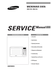
MICROWAVE OVEN
MR1031UWC
MR1032UBC
SERVICE
MICROWAVE OVEN
Manual
CONTENTS
1. Precaution
2. Specifications
3. Operating Instructions
4. Disassembly and Reassembly
5. Alignment and Adjustments
6. Troubleshooting
7. Exploded Views and Parts List
8. PCB Diagrams
9. Schematic Diagrams
SEA
PRECAUTIONS TO BE OBSERVED BEFORE AND
DURING SERVICING TO AVOID POSSIBLE
EXPOSURE TO EXCESSIVE MICROWAVE ENERGY
(a) Do not operate or allow the oven to be
operated with the door open.
(b) Make the following safety checks on
all ovens to be serviced before activating
the magnetron or other microwave
source, and make repairs as necessary:
(1) Interlock operation,
(2) proper door closing,
(3) seal and sealing surfaces (arcing,
wear, and other damage),
(4) damage to or loosening of hinges
and latches.
(5) evidence of dropping or abuse.
(c) Before turning on microwave power
for any service test or inspection within
the microwave generating
compartments, check the magnetron,
wave guide or transmission line, and
cavity for proper alignment, integrity,
and connections.
(d) Any defective or misadjusted
components in the interlock, monitor,
door seal, and microwave generation
and transmission systems shall be
repaired, replaced, or adjusted by
procedures described in this manual
before the oven is released to the
owner.
(e) A microwave leakage check to verify
compliance with the Federal
performance standard should be
performed on each oven prior to
release to the owner.
1. Precaution
Follow these special safety precautions. Although the microwave oven is completely safe during ordinary use,
repair work can be extremely hazardous due to possible exposure to microwave radiation, as well as potentially
lethal high voltages and currents.
1-1 Safety precautions (
)
1. All repairs should be done in accordance
with the procedures described in this
manual. This product complies with
Federal Performance Standard 21 CFR.
Subchapter J (DHHS).
11. To avoid any possible radiation hazard,
replace parts in accordance with the wiring
diagram. Also, use only the exact
replacements for the following parts:
Primary and secondary interlock switches,
interlock monitor switch.
2. Microwave emission check should be
performed to prior to servicing if the oven is
operative.
12. If the fuse is blown by the Interlock Monitor
Switch: Replace all of the following at the
same time: Secondary, door sensing switch
and power relay, as well as the Interlock
Monitor Switch. The correct adjustment of
these switches is described elsewhere in this
manual. Make sure that the fuse has the
correct rating for the particular model being
repaired.
3. If the oven operates with the door open :
Instruct the user not to operate the oven and
contact the manufacturer and the center for
devices and radiological health immediately.
4. Notify the Central Service Center if the
microwave leakage exceeds 5 mW/cm2
13. Design Alteration Warning:
Use exact replacement parts only, i.e.,
only those that are specified in the
drawings and parts lists of this manual.
This is especially important for the
Interlock switches, described above.
Never alter or add to the mechanical or
electrical design of the MWO. Any design
changes or additions will void the
manufacturer's warranty. Always unplug
the unit's AC power cord from the AC
power source before attempting to
remove or reinstall any component or
assembly.
5. Check all grounds.
6. Do not power the MWO from a "2-prong"
AC cord. Be sure that all of the built-in
protective devices are replaced. Restore any
missing protective shields.
7. When reinstalling the chassis and its
assemblies, be sure to restore all protective
devices, including: nonmetallic control
knobs and compartment covers.
14. Never defeat any of the B+ voltage
interlocks. Do not apply AC power to the
unit (or any of its assemblies) unless all
solid-state heat sinks are correctly installed.
8. Make sure that there are no cabinet openings
through which people -- particularly
children -- might insert objects and contact
dangerous voltages. Examples: Lamp hole,
ventilation slots.
15. Some semiconductor ("solid state") devices
are easily damaged by static electricity. Such
components are called Electrostatically
Sensitive Devices (ESDs). Examples include
integrated circuits and field -effect transistors.
Immediately before handling any
semiconductor components or assemblies,
drain the electrostatic charge from your
body by touching a known earth ground.
9. Inform the manufacturer of any oven found
to have emission in excess of 5 mW/cm2 ,
Make repairs to bring the unit into
compliance at no cost to owner and try to
determine cause.
Instruct owner not to use oven until it has
been brought into compliance.
16. Always connect a test instrument's ground
lead to the instrument chassis ground before
connecting the positive lead; always remove
the instrument's ground lead last.
CENTRAL SERVICE CENTER
10. Service technicians should remove their
watches while repairing an MWO.
- 1 -
1-2 Special Servicing Precautions (Continued)
17. When checking the continuity of the witches
or transformer, always make sure that the
power is OFF, and one of the lead wires is
disconnected.
18. Components that are critical for safety are
indicated in the circuit diagram by
shading,
or
.
19. Use replacement components that have the
same ratings, especially for flame resistance
and dielectric strength specifications. A
replacement part that does not have the
same safety characteristics as the original
might create shock, fire or other hazards.
NOTE : Connect the oven to a 20A. When connecting the oven to a 15A,
make sure that circuit breaker can operate.
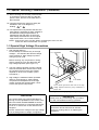
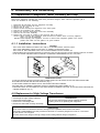
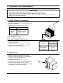
1-3 Special High Voltage Precautions
1. High Voltage Warning
Do not attempt to measure any of the high
voltages -- this includes the filament voltage
of the magnetron. High voltage is present
during any cook cycle.
H. V. Capacitor
Before touching any components or wiring,
always unplug the oven and discharge the
high voltage capacitor (See Figure 1-1)
2. The high-voltage capacitor remains charged
about 30 seconds after disconnection. Short
the negative terminal of the high-voltage
capacitor to to the oven chassis. (Use a
screwdriver.)
3. High voltage is maintained within specified
limits by close-tolerance, safety-related
components and adjustments. If the high
voltage exceeds the specified limits, check
each of the special components.
H. V. Diode
Short
Touch chassis ground first then short to the high
voltage capacitor terminal by using screwdriver or
jumper wire.
Fig. 1-1 Discharging High Voltage Capacitor
PRECAUTION
PRECAUTION
Never touch any circuit wiring with your hand
nor with uninsulated tool during operation.
There exists HIGH VOLTAGE ELECTRICITY
with high current capabilities in the circuits of the
HIGH VOLTAGE TRANSFORMER secondary
and filament terminals. It is extremely dangerous
to work on or near these circuits with the oven
energized.
DO NOT measure the voltage in the high voltage
circuit including filament voltage of magnetron.
PRECAUTION
Servicemen should remove their watches
whenever working close to or replacing the
magnetron.
- 2 -
2. Specifications
2-1 Table of Specifications
TIMER
99 MINUTES 99SECONDS
POWER SOURCE
120VAC, 60Hz
POWER CONSUMPTION
MICROWAVE : 1,500W
OUTPUT POWER
1000W ( 10 LEVEL POWER )
OPERATING FREQUENCY
2,450MHz
MAGNETRON
OM75P(31)ESS
COOLING METHOD
COOLING FAN MOTOR
OUTSIDE DIMENSIONS
2011/32"(W) x 1311/32"(H) x 145/8"(D)
NET WEIGHT
40.8 lbs.
SHIPPING WEIGHT
36.3 lbs.
- 3 -
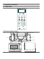
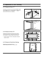
3. Operating Instructions
3-1 Control Panel
3-2 Features & External Views
Door
Light
Ventilation Holes
Safety Interlock Holes
Control Panel
Door Latches
Open Door Push
Guide Roller
297mm
Glass Tray
216mm
369mm
517mm
379mm
- 4 -
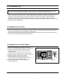
4. Disassembly and Reassembly
4-1 Replacement of Magnetron, Motor Assembly and Lamp
Remove the magnetron including the shield case, permanent magnet, choke coils and capacitors (all of
which are contained in one assembly).
1.
2.
3.
4.
5.
6.
7.
8.
Disconnect all lead wires from the magnetron and lamp.
Remove a screw securing air cover.
Remove the air cover.
Remove screws securing the magnetron to the wave guide.
Take out the magnetron very carefully.
Remove tow from the back panel of fan motor assembly.
Take out the fan motor assembly.
Remove the oven lamp by rotating to pull out from hole of air cover.
NOTE1: When removing the magnetron, make sure that its antenna does not hit any adjacent
parts, or it may be damaged.
NOTE2: When replacing the magnetron, be sure to remount the magnetron gasket in the correct
position and make sure the gasket is in good condition.
4-1 -1 Installation Instructions
CAUTION
. THIS OVEN WAS MANUFACTURED FOR USE IN A RECREATIONAL VEHICLE ONLY.
. THIS OVEN REQUIRES INSTALLATION INTO A CABINET STRUCTURE ONLY.
. THIS OVEN IS NOT DESIGNED FOR USE IN NON-CABINET INSTALLATIONS OR
FREESTANDING APPLICATIONS ADJACENT TO (WITHIN 2 FEET OF) ANY GAS OR ELECTRIC RANGE,COOKTOP, OR OVEN.
. PLUG THE THREE-PRONG POWER CORD INTO A PROPERLY GROUNDED OUTLET, 120V, 60Hz
SCREW
(Trim to outcase)
SCREW
(Trim to outcase)
SCREW
(Trim to cabinet)
(Fig. 1)
(Fig. 2)
OVEN INSTALLATION
. ALIGN THE SCREW HOLES ON UPPER AND LOWER TRIMS TO THE HOLES ON THE TOP ENCLOSURE AND
BOTTOM ENCLOSURE AND SECURE SCREWS. (Fig. 1)
. PLUG POWER CORD INTO RECEPTACLE, AND SLIDE OVEN INTO CABINET.
. SECURE OVEN TO CABINET THROUGH HOLES IN UPPER AND LOWER TRIMS. (Fig. 2)
. OVEN FEET MUST SIT ON CABINET FLOOR OR SUPPORT RUNNERS THAT ARE FLUSH WITH BOTTOM EDGE OF
CABINET OPENING. (Fig. 2)
4-2 Replacement of High Voltage Transformer
1.
2.
3.
4.
Discharge the high voltage capacitor.
Disconnect all the leads.
Remove the mounting bolts.
Reconnect the leads correctly and firmly.
PRECAUTION
Servicemen should remove their watches whenever
working close to or replacing the magnetron.
PRECAUTION
There exists HIGH VOLTAGE ELECTRICITY with high current capabilities in the circuits of the HIGH
VOLTAGE TRANSFORMER secondary and filament terminals. It is extremely dangerous to work on or near these
circuits with the oven energized.
DO NOT measure the voltage in the high voltage circuit including filament voltage of magnetron.
- 5 -
4-3 Replacement of Door Assembly
4-3-1 Removal of Door "C"
Insert flat screw driver into the gap between Door
"A" and Door "C" to remove Door "C". Be careful
when handling Door "C" because it is fragile.
Then remove the door assembly.
Door "A"
Door "C"
4-3-2 Removal of Door "E"
Door "E"
Following the procedure as shown in the figure,
insert and bend a thin metal plate between Door
"E" and Door "A" until you hear the 'tick' sound.
1. Insertion depth of the thin metal plate should be
0.5mm or less.
4-3-3 Removal of Key Door & Spring
Remove pin hinge from Door "E"
Detach spring from Door "E" and key door.
- 6 -
4-3-4 Reassembly Test
After replacement of the defective component parts of the door, reassemble it and follow the instructions
below for proper installation and adjustment so as to prevent an excessive microwave leakage.
1. When mounting the door to the oven, be sure to adjust the door parallel to the bottom line of the oven
face plate by moving the upper hinge and lower hinge in the direction necessary for proper alignment.
2. Adjust so that the door has no play between the inner door surface and oven front surface. If the door
assembly is not mounted properly, microwave energy may leak from the space between the door and oven.
3. Do the microwave leakage test.
4-4 Replacement of Fuse
1. Disconnect the oven from the power source.
2. When 20A fuse blows out by the operation of interlock monitor switch failure, replace the primary interlock
switch, door sensing switch, monitor switch and power relay.
3. When the above three switches operate properly, check if any other part such as the control circuit board,
blower motor or high voltage transformer is defective.
4-5 Replacement of Drive Motor
1. Take out the glass tray, guide roller from cavity.
2. Turn the oven upside down to replace the drive motor.
3. Remove a screw securing the drive motor cover
or disconnect the drive motor cover from base
plate by nipper.
4. Disconnect all the lead wires from the drive motor.
5. Remove screws securing the drive motor to the cavity.
6. Remove the drive motor and the coupler.
7. When replacing the drive motor, be sure to
remount it in the correct position with the coupler.
8. Connect all the leads to the drive motor.
9. Screw the drive motor cover to the base plate
with a screw driver.
- 7 -
Drive Motor
Drive Motor Cover
Base Plate
4-6 Replacement of Control Circuit Board
4-6-1 Removal of Control Box Assembly
1. Be sure to ground any static electric charge in
your body and never touch the control circuit.
2. Disconnect the connectors from the control
circuit board.
3. Remove screws securing the control box
assembly.
Control Box
4. Remove the screw securing the ground tail of
the keyboard.
Screw
4-6-2 Removal of P.C.B Assembly
1. Pull the lever end of the plastic fastener and
remove the Flexible Printed Circuit(FPC) of
membrane panel.
Screw
2. Remove screws securing the control circuit
board.
3. Right up the control circuit board from the Ass'y
control box.
4. When reconnecting the FPC connector, make
sure that the holes on the connector are properly
engaged with the hooks on the Plastic Fastener.
4-6-3 Removal of Window Display & Membrane Panel
1. Window display should not be disassembled as
its mounting tabs will be broken. If repair work
is difficult, replace with Ass'y control panel.
2. The membrane key board is attached to the
escutcheon base with doublefaced adhesive
tape. Therefore, applying hot air such as using of
hair dryer is recommended for smoother
removal.
3. When installing new membrane key board, make
sure that the surface of escutcheon base is
cleaned sufficiently so that any problems
(shorted contacts or uneven surface) can be
avoided.
- 8 -
5. Alignment and Adjustments
PRECAUTION
1. High voltage is present at the high voltage terminals during any cook cycle.
2. It is neither necessary nor advisable to attempt measurement of the high voltage.
3. Before touching any oven components or wiring, always unplug the oven from its power source and
discharge the high voltage capacitor.
5-1 High Voltage Transformer
1. Remove connectors from the transformer terminals
and check continuity.
2. Normal resistance readings are as follows:
SHV-U1040A
Secondary
99.50Ω ± 2%
Filament
Shows Continuity
Primary
0.365Ω ± 2%
(Room temperature = 20° C)
5-2 Low Voltage Transformer
1. The low voltage transformer is located on the
control circuit board.
2. Remove the low voltage transformer from the
PCB Ass'y and check continuity.
3. Normal resistor reading is shown in the table.
Terminals
5-3 Magnetron
1. Continuity checks can indicate only an open
filament or a shorted magnetron. To diagnose an
open filament or shorted magnetron :
2. Isolate the magnetron from the circuit by
disconnecting its leads.
3. A continuity check across the magnetron filament
terminals should indicate one ohm or less.
4. A continuity check between each filament terminal
and magnetron case should read open.
- 9 -
Resistance
SLV-4290U
1~2(Input)
379Ω
3~4(Output7V)
10.23Ω
5~6(Output17V)
31.91Ω
5-4 High Voltage Capacitor
1.
2.
3.
4.
5.
Check continuity of the capacitor with the meter set at the highest resistance scale.
Once the capacitor is charged, a normal capacitor shows continuity for a short time, and then indicates 9MΩ.
A shorted capacitor will show continuous continuity.
An open capacitor will show constant 9MΩ.
Resistance between each terminal and chassis should read infinite.
5-5 High Voltage Diode
1. Isolate the diode from the circuit by disconnecting its leads.
2. With the ohm-meter set at the highest resistance scale, measure across the diode terminals. Reverse the
meter leads and read the resistance. A meter with 6V, 9V or higher voltage batteries should be used to
check the front-to back resistance of the diode (otherwise an infinite resistance may be read in both
directions). The resistance of a normal diode will be infinite in one direction and several hundred KΩ in the
other direction.
5-6 Main Relay and Power Control Relay
1. The relays are located on the PCB Ass'y. Isolate them from the main circuit by disconnecting the leads.
2. Operate the microwave oven with a water load in the oven. Set the power level set to high.
3. Check continuity between terminals of the relays after the start pad is pressed.
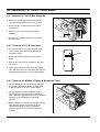
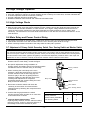
5-7 Adjustment of Primary Switch Secondary Switch, Door Sensing Switch and Monitor Switch
Precaution
For continued protection against radiation hazard, replace parts in accordance with the wiring diagram and be sure to
use the correct part number for the following switches: Primary and secondary interlock switches, Door Sensing Switch
and the interlock monitor switch (replace all together). Then follow the adjustment procedures below. After repair and
adjustment, be sure to check the continuity of all interlock switches and the interlock monitor switch.
1. When mounting Door Sensing switch and Interlock
Monitor switch to Latch Body, consult the figure.
2. No specific adjustment during installation of
Primary switch, Secondary switch, Door Sensing switch
and Monitor switch to the latch body is necessary.
3. When mounting the Latch Body to the oven
assembly, adjust the Latch Body by moving it so
that the oven door will not have any play in it.
Check for play in the door by pulling the door
assembly. Make sure that the latch keys move
smoothly after adjustment is completed.
Completely tighten the screws holding the Latch
Body to the oven assembly.
Primary Interlock
Switch
Body Latch
Interlock Monitor
Switch
4. Reconnect to Monitor switch and check the
continuity of the monitor circuit and all latch
switches again by following the components test
procedures.
Lever Switch
5. Confirm that the gap between the switch
housing and the switch actuator is no more than
0.5mm when door is closed.
Door Open Door Closed
6. Interlock Switch Replacement - When
replacing faulty switches, be sure switch mounting
tabs are not bent, broken or otherwise deficient in
their ability to secure the switches in place.
Door Sensing Switch
Primary Interlock
Monitor switch (COM-NC)
Door Sensing switch
- 10 -
∞
0
0
∞
∞
0
5-8 Output Power of Magnetron
CAUTION
MICROWAVE RADIATION
PERSONNEL SHOULD NOT ALLOW EXPOSURE TO MICROWAVE RADIATION FROM MICROWAVE
GENERATOR OR OTHER PARTS CONDUCTING MICROWAVE ENERGY.
The output power of the magnetron can be measured by performing a water temperature rise test.
Equipment needed :
* Two 1-liter cylindrical borosilicate glass vessel (Outside diameter 190 mm)
* One glass thermometer with mercury column
NOTE: Check line voltage under load. Low voltage will lower the magnetron output. Make all temperature
and time tests with accurate equipment.
1. Fill the one liter glass vessel with water.
2. Stir water in glass vessel with thermometer, and record glass vessel's temperature ("T1", 10±1° C).
3. After moving the water into another glass vessel, place it in the center of the cooking tray. Set the oven to
high power and operate for 44seconds exactly. (3 seconds included as a holding time of magnetron
oscillation:)
4. When heating is finished, stir the water again with the thermometer and measure the temperature ("T2").
5. Subtract T1 from T2. This will give you the water temperature rise. (△T)
6. The output power is obtained by the following formula;
Output Power =
4.187 x 1000 x △T+0.55xMcx(T2 -T1)
41
44 : Heating Time (sec)
41 : Counting Time (sec)
4.187 : Coefficient for Water
1000 : Water (cc)
△T : Temperature Rise (T1-T2)
To : Room Temperature
Mc : Cylindrical borosilicate glass weight
7. Normal temperature rise for this model is 9.3° C to 10.5°C at 'HIGH'.
NOTE 1: Variations or errors in the test procedure will cause a variance in the temperature rise.
Additional power test should be made if temperature rise is marginal.
- 11 -
5-9 Procedure for Measurement of Microwave Energy Leakage
1) Pour 275±15cc of 20±5° C(68±9° F) water in a beaker
which is graduated to 600cc, and place the beaker in
the center of the oven.
2) Start to operate the oven and measure the leakage by
using a microwave energy survey meter.
3) Set survey meter with dual ranges to 2,450MHz.
4) When measuring the leakage, always use the 2 inch
spacer cone with the probe. Hold the probe
perpendicular to the cabinet door. Place the spacer
cone of the probe on the door and/or cabinet door
seam and move along the seam, the door viewing
window and the exhaust openings moving the
probe in a clockwise direction at a rate of 1 inch/sec. If the leakage testing of the cabinet door seam is
taken near a corner of the door, keep the probe perpendicular to the areas making sure that the probe end
at the base of the cone does not get closer than 5cm to any metal. If it gets closer than 5cm, erroneous
readings may result.
5) Measured leakage must be less than 4mW/cm2 , after repair or adjustment.
Maximum allowable leakage is 5mW/cm2 .
4mW/cm2 is used to allow for measurement and meter accuracy
5-10 Check for Microwave Leakage
1. Remove the outer panel.
2. Pour 275±15cc of 20±5°C(68±9°F) water in a beaker
which is graduated to 600cc, and place the beaker in
the center of the oven.
3. Start the oven at the highest power level.
4. Set survey meter dual ranges to 2,450MHz.
5. Using the survey meter and spacer cone as described
above, measure near the opening of magnetron, the
surface of the air guide and the surface of the wave
guide as shown in the following photo.( but avoid the
high voltage components.) The reading should be less than 4mW/cm 2 .
5-11 Note on Measurement
1) Do not exceed the limited scale.
2) The test probe must be held on the grip of the handle, otherwise a false reading may result when the
operator's hand is between the handle and the probe.
3) When high leakage is suspected, do not move the probe horizontally along the oven surface; this may
cause damage to the probe.
4) Follow the recommendation of the manufacturer of the microwave energy survey meter.
5-12 Leakage Measuring Procedure
5-12-1 Record keeping and notification after measurement
1) After adjustment and repair of a radiarion preventing device, make a repair record for the measured
values, and keep the data.
2) If the radiation leakage is more than 4 mW/cm 2 after determining that all parts are in good condition,
functioning properly and the identical parts are replaced as listed in this manual notift that fact to ;
CENTRAL SERVICE CENTER
5-12-2 At least once a year have the microwave energy survey meter checked for accuracy by its
manufacturer.
- 12 -
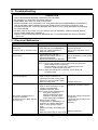
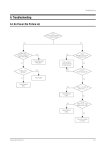
6. Troubleshooting
PRECAUTION
1.
2.
3.
4.
CHECK GROUNDING BEFORE CHECKING FOR TROUBLE.
BE CAREFUL OF THE HIGH VOLTAGE CIRCUIT.
DISCHARGE THE HIGH VOLTAGE CAPACITOR.
WHEN CHECKING THE CONTINUITY OF THE SWITCHES OR TRANSFORMER, DISCONNECT
ONE LEAD WIRE FROM THESE PARTS AND THEN CHECK CONTINUITY WITHOUT THE
POWER SOURCE ON. TO DO OTHERWISE MAY RESULT IN A FALSE READING OR DAMAGE
TO YOUR METER.
5. DO NOT TOUCH ANY PART OF THE CIRCUIT OR THE CONTROL CIRCUIT BOARD, SINCE
STATIC DISCHARGE MAY DAMAGE IT.
ALWAYS TOUCH GROUND WHILE WORKING ON IT TO DISCHARGE ANY STATIC CHARGE
BUILT UP.
6-1 Electrical Malfunction
SYMPTOM
CAUSE
CORRECTIONS
Oven is dead.
1. Open or loose lead wire harness
Fuse is OK.
2. Open thermal cutout (Magnetron)
No display and no operation at all. 3. Open low voltage transformer
4. Defective Ass'y PCB
Check fan motor when thermal
cutout is defective.
Check Ass'y PCB when LVT is
defective.
No display and no operation at all. 1. Shorted lead wire harness
Fuse is blown.
2. Defective latch switch (NOTE 1)
3. Shorted HVCapacitor
4. Shorted HVTransformer (NOTE2)
Check adjustment of, latch switch,
power relay.
NOTE 1: All of these switches must be replaced at the same time.
(refer to adjustment instructions)
Check continuity of power relay contacts and if it has
continuity, replace power relay also.
NOTE 2: When HVTransformer is replaced, check diode and
magnetron also.
Oven does not accept
key input (Program)
1. Key input is not in-Sequence
2. Open or loose connection of
membrane key pad to Ass'y PCB
3. Shorted or open membrane panel
4. Defective Ass'y PCB
1. Off-alignment of latch switches
2. Open or loose connection of high
voltage circuit especially
magnetron filament circuit
NOTE: Large contact resistance will
bring lower magnetron
filament voltage and cause
Timer starts countdown but no
magnetron to lower output
microwave oscillation.
and/or intermittent oscillation.
(No heat while oven lamp and fan
3. Defective high voltage
motor turn on.)
components H.V.Transformer H.V.
Capacitor H.V.Diode, Magnetron
4. Open or loose wiring of power
relay
5. Defective Primary, Secondary latch
switch
6. Defective power relay or Ass'y PCB
- 13 -
Refer to operation procedure.
Replace PCB main.
Adjust door and latch switches.
Check high voltage component
according to
component test procedure and
replace if it is
defective.
Replace PCB main.
6-1 Electrical Malfunction(continued)
SYMPTOM
Oven lamp and fan motor turn on
Oven can program but timer
does not start.
Microwave output is low;.
Oven takes longer time to
cook food.
CAUSE
1. Misadjustment or loose wiring
of latch switch
2. Defective latch switch
1. Open or loose wiring of latch
switch
2. Off-alignment of latch switch
3. Defective latch switch
1. Decrease in power source
voltage.
2. Open or loose wiring of
magnetron filament circuit.
(Intermittent oscillation))
3. Aging of magnetron
Fan motor turns on when plugged in Loose wiring of door sensing switch
CORRECTIONS
Adjust door and latch switches.
Adjust door and interlock
switches.
Consult electrician.
Check wire of door sensing
switch.
Oven does not operate and return to Defective Ass'y PCB
the plugged in mode.
Replace PCB main.
Loud buzzing noise can be heard.
1. Loose fan and fan motor
2. Loose screws on
H.V.Transformer
3. Shorted H.V.Diode
Tighten screws of fan motor.
Tighten screws of
H.V.Transformer.
Replace H.V.Diode.
Turntable motor does not rotate.
1. Open or loose wiring of
turntable motor.
2. Defective turntable motor.
Replace turntable motor.
1. Open or loose wiring of
latch switch
2. Operation of thermal
cutout(Magnetron)
Adjust door and latch switches.
1. Metallic ware or cooking dishes
touching on the oven wall.
2. Ceramic ware trimmed with
gold or silver powder also
causes sparks.
Inform the customer.
Do not use any type of cookware
with metallic trimming.
Oven stops operation during cooking
Sparks
Uneven cooking
Uneven intensity of microwave due
to its characteristics.
Noise from the turntable motor when Noise may result from the motor.
it starts to operate.
- 14 -
Wrap thinner parts of the food
with aluminum foil.
Use plastic wrap or cover with a
lid.
Stir once or twice while cooking
foods such as soup, cocoa, or
milk.
Replace turntable motor.
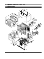
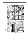
7. Exploded Views and Parts List
7-1 Exploded Views
P020
U010
D005
D015
D004
D003
D002
M015
M001
D006
M019
M018
M029
M020
M022
D007
M023
M157
D011
D049
W002
M036
C082
M099
M051
B018
C009
C005
M049
C003
C006
C004
M035
B006
B001
B002
M037
M038
M048
B009
B004
C007
M039
T001
T017
M034
U011
M047
M046
U009
- 15 -
M040
7-2 Main Parts List
No.
Code No.
Description
Specification
Q'ty
Remark
B001
3405-001034
SWITCH-MICRO
125/250VAC,16A,200GF,SPST-N
1
PRI S/W
B002
3405-001033
SWITCH-MICRO
125/250VAC,16A,200GF,SPST-N
1
MONITOR
B004
3405-001042
SWITCH-MICRO
DC 24V,0.3A,150gf,-
1
DOOR S/W
B006
DE72-00138A
BODY-LATCH
NC2000(0.6/0.8/1.2),PP,-,-,-,
1
B009
DE66-00088A
LEVER-SWITCH
NC2000(0.6/0.8/1.2),PP,-,-,
1
B018
DE96-00115A
ASSY BODY LATCH
MW850WA,NC2000(BUTTON)
1
M001
DE70-30001U
PANEL-OUTER
MR5482W,SECC,T0.6,W360,L1128
1
MR1031UWC
M001
DE70-30001Y
PANEL-OUTER
MR1032BB,SECC,T0.6,-,-,-,BLK,-
1
MR1032UBC
M015
DE39-20037J
ASSY POWER CORD
CM1020B,SJT AWG16-3,-,12
1
M019
3601-001198
FUSE-CARTRIDGE
250V,20A,SLOW-BLOW,CERAMI
1
M018
DE47-40025A
HOLDER-FUSE
KFSN-L-16,15A,NYLON#66,5G,-,
1
M020
DE96-00305A
ASSY-MOTOR FAN
SMF-5THUA,120V60Hz,2450,5
1
M022
DE63-00210A
COVER-BLOWER
5TH-1.0,PP,T1.5,-,-,-,-,-,-
1
M023
DE31-10185B
MOTOR FAN
SMF-3RDUA1,120V60Hz,-,-,2300rp
1
M029
DE47-20008A
THERMOSTAT
PW2N-52JC,100/60,250V/7.5A,H,
1
M034
DE67-00182A
COUPLER
5TH-1.0,PPS,-,-,-,-
1
M035
OM75P(31)ERHN
ASSY-MAGNETRON
OM75P(31)ERHN
1
M036
4713-001102
LAMP-INCANDESCENT
125V,-,25W,TRP,-,-,25x
1
M037
DE63-00208A
COVER-AIR
5TH-1.0,PP,-,-,-,-,-,-,-
1
M038
DE26-00088A
TRANS H.V
SHV-U1040A,120V,60HZ,2220V/3.3
1
M039
2501-001016
C-OIL
950nF,2.1KV,BK,35x54x80,20mm
1
M040
DE61-50106A
BRACKET-HVC
-,SECC,T0.8,W31,L125.8,-,-
1
M046
DE60-60025A
PIN-FOOT
PP-JI350,BLK,-,-,-,-,-,-
4
M047
DE61-40065A
FOOT
-,PP,T2x22x17mm,BLK,-,-,-
4
M048
DE61-00557C
BASE-PLATE
MR1031UWC,SGCC,T0.6,-,-,-,-
1
M049
DE31-10154A
MOTOR SYNCHRONOUS
M2HJ49ZR02,ST-16,50/60
1
M051
DE63-00209A
COVER-MGT
5TH-1.0,PP,T2.0,-,-,-,-,-,-
1
M099
DE66-90113A
LEVER-DOOR
PP(TB53-GH41),T2.5,-,-,12g,NT
1
M157
DE31-90057A
BLADE-FAN
PP,T1.5,-,3RD-W,-,-,-
1
P020
DE72-50092B
DUCT-AIR
-,SGCC,T0.6,W150,L212,-,-
1
T001
DE74-20015G
TRAY-COOKING
3RD-1.0,T6,1115G,HKS,-,-,-,
1
T017
DE97-00222A
ASSY-GUIDE ROLLER
NC-1.2CUFT,SPS(C832) B
1
U009
DE64-00562A
TRIM-LOWER
-,SECC,-,T1.0,-,WHT,-
1
MR1031UWC
U009
DE64-00562A
TRIM-LOWER
-,SECC,-,T1.0,-,BLK,-
1
MR1032UBC
U010
DE64-00564A
TRIM-UPPER
-,SECC,-,T1.0,-,WHT,1.0 CU.FT
1
MR1031UWC
U010
DE64-00564B
TRIM-UPPER
-,SECC,-,T1.0,-,BLK,1.0 CU.FT
1
MR1032UBC
U011
DE70-40311A
PLATE-BOTTOM
MR5481G,SGCC,-,T0.6,W253,-,
1
W002
DE39-00256A
WIRE HARNESS-A
MW1250WA,120V60HZ,NC2000-
1
- 16 -
7-3 Control and Door Parts List
No.
Code No.
Description
Specification
C003
RA-K2LED1-54
ASSY PCB PARTS
MR1031WC/UWC,120V60HZ
1
C004
DE34-00190D
SWITCH MEMBRANE
MR1031UWC/XAA,ENGLISH,-,
1
C004
DE34-00190F
SWITCH MEMBRANE
MR1032UBC/XAA,ENGLISH,-,
1
MR1032UBC
C005
DE72-70202J
CONTROL-PANEL
MW1030WA,ABS(VE0812),-,-,-
1
MR1031UWC
C005
DE72-70202J
CONTROL-PANEL
MW1030BA,ABS(VE0812),-,-,-
1
MR1032UBC
C006
DE61-70076A
SPRING-BUTTON
-,HSWR,PI0.6,-,OD19,L23,5T
1
C007
DE66-20275A
BUTTON-PUSH
3RD-W S1 MW5592W,-,-,-,-,9g
1
MR1031UWC
C007
DE66-20275K
BUTTON-PUSH
JE1045GBC,ABS,-,-,BLK,SI
1
MR1032UBC
C009
DE67-40179A
WINDOW-DISPLAY
-,SAN,T2.0,-,-,-,SMOG,-
1
C082
-
ASSY CONTROL-BOX
120V60Hz,MR1031UWC/XAA,
1
MR1031UWC S.N.A
C082
-
ASSY CONTROL-BOX
120V60Hz,MR1031UBC/XAA,
1
MR1032UBC S.N.A
D002
DE64-40317M
DOOR-A
MW1030WA,ABS(GENERAL),-,WHT,-,T2.
1
MR1031UWC
D002
DE64-40317T
DOOR-A
MW1030BA,ABS(HR0370),.T2.0,-,-,-,BLK,NC-1.0
1
MR1032UBC
D003
DE67-20197D
SCREEN-DOOR
MW1030WC,PET,T0.25,W210.4,L3
1
D004
DE94-00910A
ASSY DOOR-E(COATING)
MW1030WC/XAA,BLK,5T
1
D005
DE01-00118A
FILM-DOOR
MW5896W,-,-,L185,T0.15,W304,-,
1
D006
DE64-40012A
DOOR-C
-,RESIN-PP(TB53),BLACK,-,-,-,CE94
1
D007
DE61-70128A
SPRING-KEY
-,HSWR,PI0.6,D5,OD6,L23.5,21
1
D011
DE64-40006F
DOOR-KEY
POM(F20-02),-,-,12G,BLK,MW7897G
1
D015
DE94-00912A
ASSY DOOR-SUB
MW1030WC/XAA,-,5TH-1.0
1
D049
-
ASSY DOOR
MW1030WC/XAA,PURE-WHT,120V/60H
1
MR1031UWC S.N.A
D049
-
ASSY DOOR
MW1030WC/XAA,BLK,120V/60H
1
MR1032UBC S.N.A
S.N.A : SERVICE NOT AVAILABLE
- 17 -
Q'ty
Remark
MR1031UWC
7-4 Standard Parts List
Code No.
Description
Specification
Q'ty
Remark
DE92-90522A
ASSY-SCREW PACK
MR5481G,SCREW-A(6EA),-,-,-,-
1
DE60-10082H
SCREW-A
-,-,-,-,2S-4X12,TOOTHED,-,-,-,-
1
P-C-EA
DE60-10082H
SCREW-A
-,-,-,-,2S-4X12,TOOTHED,-,-,-,-
3
PN/OUT
DE60-10098A
SCREW-ASSY TAP TITE
-,GLD,SWRCH18A,ZPC2,PH,TC,-,M4X8,WT,-
2
M/DRIV
DE60-10098A
SCREW-ASSY TAP TITE
-,GLD,SWRCH18A,ZPC2,PH,TC,-,M4X8,WT,-
1
HVD
DE60-10195A
SCREW-STAR POLE
-,SWCH18A,4,12,TH,*,-,2,ZNC,-
2
O/PANEL
DE60-10088A
SCREW-TAP PH
-,-,FEFZY,PLAIN,PH,M3,-,L8,-,-
2
DE60-10059A
SCREW-TAP TH
-,-,SUS410,CR,TH,M4,-,L8,-,-
2
C/CEILING
DE60-10070A
SCREW-TAP TH
-,-,FEFZY,2-SLOT,TH,M4,-,L12,-,-
3
B-PLTE
DE60-10070A
SCREW-TAP TH
-,-,FEFZY,2-SLOT,TH,M4,-,L12,-,-
2
BD-LAT
DE60-10070A
SCREW-TAP TH
-,-,FEFZY,2-SLOT,TH,M4,-,L12,-,-
2
CN-BOX
DE60-10070A
SCREW-TAP TH
-,-,FEFZY,2-SLOT,TH,M4,-,L12,-,-
1
CV/AIR
DE60-10070A
SCREW-TAP TH
-,-,FEFZY,2-SLOT,TH,M4,-,L12,-,-
2
MGT-TCO
DE60-10070A
SCREW-TAP TH
-,-,FEFZY,2-SLOT,TH,M4,-,L12,-,-
2
MO/FAN
DE60-10070A
SCREW-TAP TH
-,-,FEFZY,2-SLOT,TH,M4,-,L12,-,-
1
S-M-EA
DE60-10012A
SCREW-TAP TITE
-,SWR10,M4,L10,TH,+,-,3,ZPC2,-
1
DE60-10080B
SCREW-WASHER
-,2S,SWRCH18A,ZP2,PH,PI5,-,L10,-,-
4
MGT
DE60-10080B
SCREW-WASHER
-,2S,SWRCH18A,ZP2,PH,PI5,-,L10,-,-
4
TNS-HV
- 18 -
-
-
-
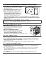
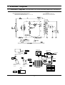
8. P.C.B Diagrams
8-1 P.C.B Diagrams
(This Document can not be used without Samsung's authorization)
- 19 -
8-2 P.C.B Parts List
Code No.
Description
Specification
Q'ty
Remark
2007-000546
R-CHIP
20KOHM,5%,1/10W,DA,TP,2012
1
R32
3501-001155
RELAY-MINIATURE
24VDC,200MW,3000MA,1FORMA,10MS,10MS
1
RY01
3501-001188
RELAY-POWER
24V DC,0.53W,-,1FormA,9.3ms,10mS
1
RY02
3708-001551
CONNECTOR-FPC/FFC/PIC
14P,1.25mm,STRAIGHT,SN
1
CN04
DE07-00021K
LED DISPLAY
CSQ-4246G-10,NC2000-CMO,-,40
1
LED1
DE09-00201A
IC MICOM
TMP87CH47U-3CG1,SM-200102-BN,-,-
1
IC01
DE26-00037A
TRANS-L.V
SLV-4290U,120V,60Hz,AC17V/7V,-,35*10,PIN,-
1
LVT1
DE30-20016A
BUZZER
CBE2220BA,STICK,-,-,-,-,-,-,-
1
BUZ1
0401-001083
DIODE-SWITCHING
MM4148,100V,150MA,LL-34,TP
5
D08~D12
0401-001083
DIODE-SWITCHING
MM4148,100V,150MA,LL-34,TP
9
D15~D23
0402-001103
DIODE-RECTIFIER
1T4,400V,1A,TS-1,TP
7
D01~D07
0403-001288
DIODE-ZENER
ZMM55C5V1,4.8-5.4V,500MW,LL-34,TP
1
ZD01
0501-000465
TR-SMALL SIGNAL
MMBT3904,NPN,350MW,SOT-23,TP,30-300
1
TR01
0504-001008
TR-DIGITAL
RN2427,PNP,200MW,2.2K/10K,SOT-23,TP
5
TR09~TR13
0504-001080
TR-DIGITAL
KRC246S,NPN,200mW,2.2K/10K,SOT-23,TP
3
TR02,TR05,TR08
1202-000141
IC-VOLTAGE COMP.
7033,SOT-89,3P,-,SINGLE,0V,-,P
1
IC03
1203-001037
IC-VOLTAGE REGULATOR
78L05,SOT-89,3P,185MIL,PLASTIC
1
IC02
1405-000001
VARISTOR
470V,1250A,14x7.5mm,TP
1
ZNR1
2007-000033
R-CHIP
0OHM,5%,1/8W,DA,TP,3216
4
J11~J13,J16
2007-000282
R-CHIP
100KOHM,5%,1/10W,DA,TP,2012
2
R27,R28
2007-000300
R-CHIP
10KOHM,5%,1/10W,DA,TP,2012
3
R07,R08,R09
2007-000346
R-CHIP
120OHM,5%,1/8W,DA,TP,3216
8
R19~R26
2007-000468
R-CHIP
1KOHM,5%,1/10W,DA,TP,2012
6
R01,R03~R05,R10,R13
2007-000671
R-CHIP
2KOHM,5%,1/10W,DA,TP,2012
1
R02
2007-000931
R-CHIP
470OHM,5%,1/10W,DA,TP,2012
1
R06
2007-000941
R-CHIP
47KOHM,5%,1/10W,DA,TP,2012
5
R14~R18
2203-000444
C-CERAMIC,CHIP
1nF,10%,50V,X7R,TP,2012,-
6
C13~C17,C20
2203-001608
C-CERAMIC,CHIP
22nF,+80-20%,50V,Y5V,TP,2012
4
C09~C12
2401-000151
C-AL
1000uF,20%,25V,GP,TP,10x20,5
1
C02
2401-000244
C-AL
100uF,20%,10V,GP,TP,6.3x7,5
1
C03
2401-000911
C-AL
22uF,20%,16V,GP,TP,5x7,5
2
C04,C06
2401-002075
C-AL
4.7uF,20%,50V,GP,TP,5x11,5
1
C05
2401-002598
C-AL
220uF,20%,50V,GP,TP,10x16,5
1
C01
2802-000188
RESONATOR-CERAMIC
8MHz,0.5%,TP,10.0x5.0x8.0mm
1
XTL1
3711-000881
CONNECTOR-HEADER
BOX,3P,1R,2.5mm,STRAIGHT,SN
1
CN03
3711-004143
CONNECTOR-HEADER
BOX,2P/3P,1R,5mm/2.5mm,STRAIGH
1
CN02
DE39-60001A
WIRE-SO COPPER
,PI0.6,SN,T,52MM TAPING_WIRE,
10
J01~J10
- 20 -
9. Schematic Diagrams
9-1 Schematic Diagrams
(This Document can not be used without Samsung's authorization)
NOTE: CIRCUIT SHOWN WITH DOOR IS OPENED POSITION.
NOTE: FOR SERVICE REPLACEMENT USE 16 GA 105° C
THERMOPLASTIC COVERED WIRE EXCEPT
FOR HIGH VOLTAGE LEADS OR AS NOTED ON SPECIAL LEADS.
WARNING
POWER MUST BE DISCONNECTED
BEFORE SERVICING THIS APPLIANCE
MAGNETRON
BLK BLU
HIGH VOLTAGE
DIODE
BLK
ORG
ORG
TO CHASSIS
BLK
SECONDARY SWITCH
TOP
FA
F
RED
RED
HIGH VOLTAGE CAPACITOR
BLU BLU
RED
WHT
DOOR SENSING SWITCH
BOTTOM
MONITOR SWITCH
CENTER
BLK
HIGH VOLTAGE
TRANSFORMER
WHT
RED WHT
POWER RELAY
- 21 -
RED
RED
SYMBOL
COLOR
ORG
WHT
BLK
BLU
RED
ORANGE
WHITE
BLACK
BLUE
RED
ELECTRONICS
This Service Manual is a property of Samsung Electronics Co.,Ltd.
Any unauthorized use of Manual can be punished under applicable
International and/or domestic law
©Samsung Electronics Co., Ltd. June 2003
Printed in Korea
Code No. :DE68-03208A