1
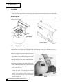
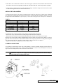
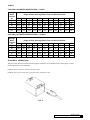
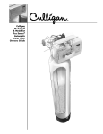
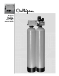
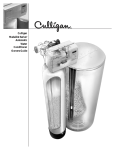
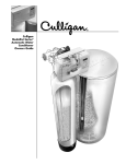
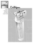
Cat. No. 01882280
Rev. C 1/18/01
DCO#1991
Installation
and Operating
Instructions
with Parts List
CULLIGAN
MEDALLIST SERIES™
AUTOMATIC WATER FILTERS
With Cullar®, Cullneu®, or
Cullsan® Media
Models from 2001
©2001 Culligan International Company
Printed in USA
Attention Culligan Customer:
Your local independently operated Culligan dealer employs trained
service and maintenance personnel who are experienced in the
installation, function and repair of Culligan equipment. This
publication is written specifically for these individuals and is
intended for their use.
We encourage Culligan users to learn about Culligan products,
but we believe that product knowledge is best obtained by consulting with your Culligan dealer. Untrained individuals who use
this manual assume the risk of any resulting property damage or
personal injury.
WARNING - Prior to servicing equipment, disconnect
power supply to prevent electrical shock.
Culligan International
One Culligan Parkway
Northbrook, IL 60062
847-205-6000
Installation
and Operating
Instructions
with Parts List
CULLIGAN
MEDALLIST SERIES™
AUTOMATIC WATER FILTERS
With Cullar®, Cullneu®, or
Cullsan® Media
Models from 2001
Table of Contents
Page
Introduction .............................................................. 2
Specifications ........................................................... 3
Component Description ........................................... 4
Preparation .............................................................. 5
Filling Procedure ...................................................... 9
Installation .............................................................. 10
Settings .................................................................. 13
Start-Up Procedure ................................................ 15
Operation ............................................................... 16
Electrical Schematic ............................................... 18
Parts List ................................................................ 19
Introduction
For installations in Massachusetts, the Commonwealth of Massachusetts Plumbing code 248 CMR shall be
adhered to. Consult with your licensed plumber for installation of this system.
SAFE PRACTICES
Throughout this manual there are paragraphs set off by special headings.
NOTICE: Notice is used to emphasize installation, operation or maintenance information which is important, but
does not present any hazard.
Example: NOTICE: The nipple must extend no more than 1 inch above the cover plate.
CAUTION: Caution is used when failure to follow directions could result in damage to equipment or
property. Example:
CAUTION: Disassembly while under water pressure can result in flooding.
WARNING: Warning is used to indicate a hazard which could cause injury or death if ignored. Example:
WARNING! ELECTRICAL SHOCK HAZARD! UNPLUG THE UNIT BEFORE
REMOVING THE TIMER MECHANISM OR COVER PLATES!
The Culligan water conditioner bears two separate serial numbers; one for the control assembly and one for the
media tank. The control assembly serial number can be found on the left rear side of the timer mounting plate. The
media tank serial number is on the side of the tank. DO NOT REMOVE OR DESTROY THESE SERIAL
NUMBER DECALS. THEY MUST BE REFERENCED IF EVER YOU REQUIRE REPAIRS OR PARTS
REPLACEMENT UNDER WARRANTY.
If you wish to service your system or maintain replacement components, please contact your local Culligan dealer
or 1-847-205-6000 for a dealer near you.
This publication is based on information available when approved for printing. Continuing design refinement
could cause changes that may not be included in this publication.
Please read this booklet carefully before beginning the installation of the Culligan Medallist Series™ Water Filter.
It contains important information about the unit, including the tools and materials needed for installation, accessories
available for hook-up to the plumbing, and instructions covering installation, settings, start-up, and operation. The
Culligan Medallist Water Filter have been thoughtfully designed and engineered to provide conditioned water for
many years when properly applied, installed and operated.
This system and installation must comply with state and local regulations.
The Medallist Automatic Cullar® filter has been tested and validated by WQA against
WQA S-200 for the effective reduction of chlorine up to 100,000 gallons (8" Filter) and
130,000 gallons (10" Filter).
The Medallist Automatic Filtr-Cleer® Filter has been tested and validated by WQA against WQA S-200 for Class
III (5-15um) particulate reduction as verified and substantiated by test data.
The Medallist Automatic Cullneu® Filter has been tested and validated by WQA against WQA S-200 for
neutralization up to 13,000 gallons for the 8" Cullneu and 20,000 gallons for the 10" Cullneu as verified and
substantiated by test data.
2
CULLIGAN MEDALLIST SERIES™ WATER FILTERS
Specifications and Limitations
8-INCH
10-INCH
GENERAL
Mineral Tank Size1
Control
Timer
Temperature Limits
Water Pressure Limits
Electrical Requirements
Electrical Power Consumption, Min./Max.
8 x 44 in.
Power Valve
Electronic
33-120°F
20-120 psi
24V/60 Hz
3 Watts/35 Watts
10 x 54 in.
Power Valve
Electronic
33-120°F
20-120 psi
24V/60 Hz
3 Watts/35 Watts
FILTR-CLEER®
Rated Service Flow
@ Initial Pressure Drop
Minimum Practical Filtration Size
Maximum Particulate Matter
Maximum Suspended Solids
Drain Flow, Maximum3
pH Limitation
Recharge Time4
Recharge Water Consumption, Av.5
Freeboard2
Height Overall
7.8 gpm
@ 15 psi
10 microns
150 NTU
150 mg/L
4.5 gpm
6.0 - 9.5
80 min.
100 gal.
10.5 ± 1 inches
51 in.
9.0 gpm
@ 15 psi
10 microns
150 NTU
150 mg/L
7.0 gpm
6.0 - 9.5
80 min.
115 gal.
11.5 ± 1 inches
63 in.
CULLAR®
Rated Service Flow
@ Pressure Drop
Drain Flow, Maximum3
pH Limitation
Recharge Time4
Recharge Water Consumption, Av.5
Cullar Media Volume
Cullsan® Underbedding Media Amount
Freeboard2
Height Overall
Rated Capacity
4.0 gpm
@ 5.0 psi
2 gpm
5.0 - 11.0
80 min.
53 gal.
0.75 cu. ft.
10 lbs. (.1 ft3)
14 ± 1 inches
51 in.
100,000 gallons
4.0 gpm
@ 5.0 psi
5.5 gpm
5.0 - 11.0
80 min.
83 gal.
1.0 cu. ft.
20 lbs. (.2 ft3)
24 ± 1 inches
63 in.
130,000 gallons
CULLNEU®
Rated Service Flow
@ Pressure Drop
Drain Flow, Maximum3
pH Limitation*
Recharge Time4
Recharge Water Consumption, Av.5
Cullneu Media Volume
Freeboard2
Height Overall
2.7 gpm
@ 4 psi
3.5 gpm
5.8 - 6.2
80 min.
53 gal.
1.0 cu. ft.
11 ± 1 inches
51 in.
4.0 gpm
@ 4.0 psi
5.5 gpm
5.8 - 6.2
80 min.
83 gal.
1.5 cu. ft.
21 ± 1 inches
63 in.
1 Bottom of tank to top of tank fittings.
2 Top of media to top of inlet fitting.
3 Backwash at 120 psi line pressure.
4 Factory setting.
5 At factory setting and 120 psi line pressure.
6 Top of media to back top edge of port openings.
*NOTE: Under dynamic conditions, it may be necessary to mix five parts Cullneu with one part Cullneu C to effectively raise the pH.
SPECIFICATIONS AND LIMITATIONS
3
Component Description
CONTROL VALVE ASSEMBLY
The reliable Power Valve directs the flow of water during recharge. Constructed of durable, non-corroding materials,
the piston-operated design assures positive, accurate positioning even on turbid problem water supplies. Time and
frequency of recharge are controlled by an adjustable, yet simple, circuit board. The circuit board can be adjusted
to suit a wide range of water types and family sizes.
MEDIA TANK
The media tank contains the outlet manifold.
NOTICE: The media tank assemblies do not contain filter media, which is shipped separately. See the section on
Installation Procedure (Page 10).
BYPASS VALVE
Includes the Cul-Flo-Valv®, interconnecting coupling and screws necessary for assembly.
4
CULLIGAN MEDALLIST SERIES™ WATER FILTERS
Preparation
The success of the installation will depend to a great extent on advance planning and preparation. Careful attention
to the unit's location, accessibility to electrical and drain facilities, and the availability of the proper tools will
ensure a professional looking installation. Of utmost importance is the assurance that the filter has been properly
applied and meets all specifications.
APPLICATION
Correct application is directly associated with the performance and life expectancy of any water conditioner. It is
important, therefore, to understand how your Culligan® Water Filter functions, and to know its capabilities and
limitations so that a correct application can be made. By following the guidelines and recommendations set forth
in this manual, you can be certain your conditioner is applied correctly.
FILTR-CLEER®
The Filtr-Cleer Automatic Water Filter is capable of removing particulate matter down to 10 microns particle size.
It will not remove color, organics, collodial turbidity or dissolved solids. Some applications follow:
• Removal of suspended matters in any water system.
• Removal of particulate matter, such as clay, mud, etc.
• Prefiltration of oxidized iron ahead of an automatic or manual softener.
• Removal of light sand. NOTICE: If sands cannot be removed from the Filtr-Cleer tank during backwashing,
a sand trap should be installed.
• After the retention tank when a Cul-Cleer® system is used to correct hydrogen sulfide or collodial suspension
problems.
The quality and number of gallons filtered water between backwashes will depend upon the amount, type, and size
of the particulate matter being filtered. If a water sample is sent to our laboratory, where application of a Filtr-Cleer
unit is contemplated, write "Filtr-Cleer Analysis" on the sample tag. Send an additional sample of water for a
standard water analysis. The laboratory will test for Nephelometric Turbidity Units (NTU) and suspended solids
(mg/L). The sample will also be filtered through 10 micron filter paper and NTU run on a filtered sample. If the
NTU of the raw water exceeds 150, suspended solids exceed 150 mg/L or the filtered water through the 10 micron
filter paper is of an unacceptable quality, a Filtr-Cleer filter may not be applicable. As a guide, the U.S. Public
Health Drinking Water standards states the turbidity should not exceed 1 NTU. The exact number of gallons
filtered between backwashes cannot be given because of many variables.
CULLAR® FILTER
Automatic Water Filter with Cullar Media will control chlorine and other common bad tastes and odors, and will
also remove most objectional organic colors. It will not remove hydrogen sulfide. It is important to note that
whenever the cause of an objectionable taste or odor has not been established, Health Authorities should determine
if water is safe to drink. If bacterial contamination is present, a Cul-Cleer system is indicated. Do not use with
water that is microbiologically unsafe or of unknown quality without adequate disinfection before or after the
system.
CULLNEU® FILTER
Automatic Water Filter with Cullneu Media will neutralize slightly acid water (pH of 5.8 or 6.2) and thus help to
prevent unsightly brown or green stains due to corrosion of household plumbing. If the pH is from 5 to 6, 1 part of
Cullneu C media should be mixed with 5 parts of Cullneu media to provide additional neutralizing capability. If
the water to be treated has a pH less than 5, a high hardness, or a high carbon dioxide level, Cullneu may not be
applicable; a solution feeder should be used. Since Cullneu adds hardness, it should be used prior to a softener.
NOTICE: Under dynamic conditions it may be necessary to mix 5 parts Cullneu with 1 part Cullneu C to effectively
raise the pH.
In order to size and apply the equipment correctly, a complete analysis of the water supply should be obtained.
This can best be accomplished by contacting the local Culligan dealer, who will be able to test the water supply
right at the site, or arrange to have one or more water samples sent to the Culligan laboratory for a more detailed
analysis.
PREPARATION
5
Culligan water filters may be applied alone or in conjunction with other equipment. They
should only be applied, however, within the specifications listed in this manual. These
specifications establish the boundaries within which the conditioner will perform most
efficiently.
PRESSURE
The conditioner is designed to operate within a pressure range of 20 to 120 psi. Pressures
below 20 psi may cause the unit to perform and recharge inefficiently, while pressures above
120 psi can cause damage and noisy operation of the control valve.
Low pressure is generally not a problem with municipal water supplies, although some
adjustments of the well pump system may be required on private supplies. Although
uncommon, some municipal supplies may exceed the high pressure limit. A pressure reducing
valve should be installed if such pressures are encountered. Keep in mind, also, that some
municipal supplies have higher pressure during nighttime hours.
Check the available water pressure with a gauge assembly to determine what adjustments, if PN 00-3044-50
any, are necessary (Figure 1). Place the gauge on a raw water line and open a nearby faucet.
FIG. 1
Adjust the faucet until the flow is about 5 gallons per minute and check the pressure. In the
case of a private well system, allow water to run until the pump cuts in. If the pressure is less than 20 psi at this
point, adjust the pump pressure switch as required to raise the cut-in pressure above 20 psi.
PRESSURE DROP
Whenever water is flowing, a certain amount of pressure is lost due to resistance from pipe, fittings, and appliances
connected to the water supply. The amount of pressure drop encountered depends on how fast the water is flowing
and how much resistance it meets. The amount of pressure available at a tap is also determined by its height above
the source of the supply. For example, if water pressure in the basement is 50 psi, it will be about 45 psi on the
ground floor, and about 40 psi on the second floor, or a reduction of about 5 psi for every 10 feet of elevation.
Particularly in the case of private water supplies, it may be necessary to increase the pump pressure to overcome
pressure drop through the conditioner so that adequate pressure is available at all taps.
As the filter bed becomes loaded with the particulate matter it has removed, pressure drop will increase. The filter
must be backwashed when the pressure drop reaches unacceptable levels. The filter should always be installed
prior to the water heater.
LOCATION
The location in which the filter is placed should be selected on the basis of the following factors. If at all possible,
lines normally requiring unconditioned water should be bypassed (Figure 2). This may not be practical, however,
in all cases.
TEMPERATURE
Temperature is an important consideration. The filter should be installed in an area protected from extremes in
temperature. Do not allow the filter to freeze, but at the same time do not install it directly adjacent to furnace or
water heater, or in an area where it may be exposed to direct sunlight. An outdoor location is not recommended
unless the conditioner is protected from rain, blowing sand and dust, and temperature extremes.
ELECTRICAL REQUIREMENTS AND POWER CONSUMPTION
The unit should be located near an electrical outlet, preferably one not controlled by a switch which could accidentally
be turned off. The control is provided with a 10-foot cord with a wall mount transformer and should be plugged
into a grounded receptacle.
6
CULLIGAN MEDALLIST SERIES™ WATER FILTERS
FIG. 2
When producing filtered water, the unit will use about 3 watts of electricity — this is required for the circuit board.
Even during recharge, however, the unit will consume no more than about 35 watts, or a little more than half the
electricity of a 60 watt light bulb.
DRAIN REQUIREMENTS
An open, free-flowing drain capable of carrying the maximum drain flow rate may be used. This may take the form
of a floor drain, utility sink, or stand pipe. Most plumbing codes, however, require an air gap at the discharge of the
drain line to prevent possible back-siphoning of drain contents. Refer to the Drain Line Chart table 1, page 11, for
allowable drain line length.
SPACE REQUIREMENTS
Along with the availability of drainage and electricity, the physical location of the unit must be considered. Six to
twelve inches clearance should be provided behind the unit for running plumbing and drain lines, and four feet
above the top of the unit for service access. The floor must be level and smooth.
TOOLS AND MATERIALS
The following tools and supplies will be needed, depending on installation method. Observe all applicable codes.
All Installations
• Safety glasses
• Phillips screwdrivers, small and medium tip
• Gauge assembly (PN 00-3044-50 or equivalent)
• Silicone lubricant (PN 00-4715-07 or equivalent) - DO NOT USE PETROLEUM-BASED LUBRICANTS
• A bucket, preferably light-colored
• Towels
PREPARATION
7
Special Tools
• Torch, solder and flux for sweat copper connections
• Threading tools, pipe wrenches and thread sealer for threaded connections
• Saw, solvent and cement for plastic pipe connections
Materials
• Drain line, 1/2" (PN 00-3030-82, gray, semi-flexible; or PN 00-3319-46, black, semi-rigid; or equivalent)
• Thread sealing tape
• Pressure reducing valve (if pressure exceeds 120 psi)
• Pipe and fittings suited to the type of installation
• Plastic pipe (if permitted by local plumbing codes) — saw, solvent cement and rags
If the household plumbing is galvanized and you intend to make the installation with copper, or vice versa, obtain
dielectric unions to prevent galvanic (dissimilar metal) corrosion.
All installations will require 1/2" drain line, (PN 00-3030-82, gray, semi-flexible; or PN 00-3319-46, black, rigid).
Obtain slightly more than you think you will need to cover for the elevation over doorways and so on.
BYPASS
Although the filter's control valve has a feature which makes unfiltered water available during backwash, a separate
manual bypass is recommended to permit unfiltered water to be used in those lines which cannot be bypassed
when the filter is plumbed in, or to permit use of water in the event the unit must be removed from service for any
reason.
The unit includes a Cul-Flo-Valv® bypass with 3/4" NPT connections, PN 01-0102-38, (Figure 5). Other available
sizes:
Part No.
01012488
01010237
8
Description
Cul-Flo-Valv Bypass
Cul-Flo-Valv Bypass
CULLIGAN MEDALLIST SERIES™ WATER FILTERS
Size
3/4-inch Sweat
1-inch NPT
Filling Procedure
FILTR-CLEER® WATER FILTER
The 8" Filtr-Cleer filters are shipped with one media pack and the 10" Filtr-Cleer filters are shipped with two
media packs. Verify that the proper number of media packs are on site before loading the tank. Place the
manifold inside the tank. Position the tip of the manifold in the recess located in the bottom of the tank.
•
•
•
•
•
•
•
Cover the top of the manifold with a clean rag.
Place a wide-mouth funnel in the tank opening.
Open the media pack(s) by cutting along the bottom of the carton and lifting up to expose the four individual
media packages (Figure 3). Notice: The performance of the filter may be severely affected if the media are not
added in the proper sequence shown.
With no water in the tank, slowly pour the Cullsan® media into the tank. Note: The 10" filter requires the
Cullsan U from both of the media packs. Shake tank to level the media.
With no water in the tank, slowly pour the Cullsan G-50 media into the tank and level. Note: The 10: filter
requires the Cullsan G-50 from both of the media packs.
With no water in the tank, slowly pour the Cullsan A media into the tank and level. Note: The 10" filter
requires the Cullsan A from both of the media packs.
Slowly pour the Cullcite® media into the tank and level. Note: The 10" filter requires the Cullcite from both of
the media packs.
CULLAR® FILTERS
Cullar filters are shipped with one cubic foot of carbon and a 20 lb bag of Cullsan underbedding. Verify that the
proper amount of media is on site before loading the tank.
• Place the manifold inside the tank. Position the tip of the manifold in the recess located in the bottom of the
tank.
• Cover the top of the manifold with a clean rag.
• Place a wide mouth funnel in the tank opening.
• Open the bag of Cullsan underbedding. On 8" Cullar units, slowly pour approximately half the contents of the
bag into the tank. On 10" Cullar units, pour the entire contents into the tank. Shake the tank to level the media.
• Open the bag of carbon. On 8" Cullar units, slowly pour the carbon into the tank via the funnel until the
carbon is within 13" - 14" of the top of the tank. On 10" Cullar units, slowly pour the entire contents of the bag
into the tank. Shake the tank to level the media.
• Remove the rag from the manifold.
• Fill the tank with water and allow the media to soak for 24-48 hours. The water level in the tank will decrease
as the media soaks up water. Add water to the tank to keep the media submerged so all of the media gets
saturated.
CULLNEU® FILTERS
Cullneu filters are shipped with 2 bags of Cullneu with 8" filters and
3 bags of Cullneu with 10" filters. Verify that the proper amount
of media is on site before loading.
• Place the manifold inside the tank. Position the tip of the
manifold in the recess located in the bottom of the tank.
• Cover the top of the manifold with a clean rag.
• Place a wide mouth funnel in the tank opening. The Cullneu
media should be added with no water in the tank.
• For 8" Cullneu filters, slowly pour the entire contents of one
bag of media and enough media from the second bag to raise the
level of media in the tank to within 11" of the top of the tank.
• For 10" Cullneu filters, slowly pour the entire contents of two
bags of media and enough media from the third bag to raise the
level of media in the tanks to within 21" of the top of the tank.
DO NOT OVERFILL. Overfilling will result in excess media being
lost to drain during backwash, possibly plugging the control valve.
Shake the tank to level the media.
MEDIA-PAK
FIG. 3
FILLING PROCEDURE
9
Installation
PLACEMENT
Refer to Fig. 2.
• Set the media tank on a solid, level surface near water, drain and electrical facilities. Place the outlet (black
coupling) of the tank on the left.
INSTALL DECALS
Locate the data plate decals and model decals packed with the control valve. Adhere them to the cover and backplate
as shown in Figs. 4 and 5.
FIG. 4
FIG. 5
MOUNT THE CONTROL VALVE
Assemble the control valve to the media tank as follows, See Fig. 6.
1. Lubricate the O-ring sealing area of the adapter and of the tank with silicone grease. NOTICE: Do not use a
petroleum base lubricant, for this will cause swelling of the rubber parts.
2. Remove the large O-ring from the parts pack (located
in the tank adapter carton) and assemble the O-ring
onto the adapter. Be sure that the O-ring is fully seated
against the flat undersurface of the adapter.
3. Lubricate the large O-ring and the outlet manifold Oring with silicone grease.
4. Thread the valve adapter into the tank, making certain
that the outlet manifold fits securely into the manifold
O-ring. A strong hand-tight assembly is sufficient to
provide a leak-free seal.
5. NOTICE: The black molded tank adapter is marked
with "IN" and "OUT", corresponding to the inlet and
outlet of the tank. Position the tank with the inlet
coupling on the right and the outlet coupling on the
left. Lubricate the two O-rings of the tank couplings
with silicone lubricant.
10 CULLIGAN MEDALLIST SERIES™ WATER FILTERS
FIG. 6
6. The control valve is marked also with "IN" and "OUT" (Figure 7). Place the control onto the tank with the inlet
and outlet of the control corresponding with the inlet and outlet of the tank. Press firmly onto the couplings.
7. Locate the two U-clamps and screws in the small parts package. Install the clamps on both sides of the control
as indicated in Figure 8 and secure them with the screws.
INSTALL THE FLOW CONTROL
As shipped from the factory, each control is equipped with a 2 gpm flow control for 8" Cullar® filters. Additional
flow controls are included with each unit for conversion for use with other filter tanks. Refer to Table 1 to select
the proper flow control. NOTICE: To prevent injury, convert units to the proper flow control prior to installation.
TABLE 1
Filter
Flow Control
8" Cullar
2.0 gpm
10" Cullar
5.5 gpm
3.5 gpm
8" Cullneu®
10" Cullneu
5.5 gpm
4.5 gpm
8" Filtr-Cleer®
10" Filtr-Cleer
7.0 gpm*
* Use with flow control spacer provided.
Color
Brown
Black
Green
Black
Red
Black (Thin)
For backwash flow control conversion, refer to Figure 7 and instructions listed below.
• Remove the u-clip of the drain elbow assembly and pull the drain elbow straight off.
• Remove the back wash flow control located behind the elbow. Put the correct restrictor in its place.
Insert the flow control washer with the molded numbers facing toward the valve body. Refer to Table 1. For the 5.5
gpm flow control, insert the flow control with the molded "5.5" facing away from the valve body. Insert the plastic
flow control spacer after the 7 gpm flow control washer on the 10" Filtr-Cleer. See Figure 5.
• Replace the drain elbow assembly and secure it with the u-clip.
PLUMBING CONNECTIONS
Two methods of connecting the water filter to the plumbing system are available. Shipped with each filter is a
Culligan® Cul-Flo-Valv® bypass valve, either PN 01-0124-88 or PN 01-0102-38. If local conditions warrant, you
may use the sweat adaptor kits, PN 00-3314-44 or PN 00-3314-45.
CAUTION: Close the inlet supply line and relieve system pressure before cutting
into the plumbing! Flooding could result!
FIG. 7
FIG. 8
INSTALLATION 11
FIG. 9
FIG. 10
CAUTION: When making sweat connections, remove all plastic and rubber
components which contact brass or copper. Damage to these components may
result when not removed.
BYPASS VALVE INSTALLATION
The bypass valve connects directly to the backplate of the valve with a pair of screws (Figure 8). To facilitate this
connection, remove the plate by pulling up on the u-clip on the back of the valve. Lubricate all o-rings with silicon
lubricant.
CAUTION: When reinstalling back plate to control valve, make sure the u-clip fully
engages the two bottom holes of the bracket (Figure 9). Secure bracket from the top
with the two mounting screws provided.
SWEAT ADAPTOR INSTALLATION
The sweat adaptors use a snap ring to hold them to the backplate of the control valve. The back plate will need to
be removed from the valve for this connection. A pair of snap ring pliers, PN 00-5916-09, are needed for this
connection.
DRAIN LINE CONNECTION
Refer to Figure 10 and Table 2, under the applicable tank size for drain line length and height limitations.
•
•
•
•
Remove 1/2" pipe clamp from end of drain elbow.
Route a length of 1/2" drain line from the drain elbow to the drain.
Fasten the drain line to the elbow with the clamp.
Secure the drain line to the drain to prevent its movement during regeneration. A loop in the end of the tube will
keep it filled with water and will reduce splashing at the beginning of each regeneration.
NOTICE: Observe all plumbing codes. Most codes require an anti-siphon device or air gap at the discharge
point!
12 CULLIGAN MEDALLIST SERIES™ WATER FILTERS
TABLE 2
CULLIGAN® AUTOMATIC WATER FILTERS — 8-INCH
Average
Water
Pressure
psi
30
4"
56
1 ft.
50
2 ft.
40
3 ft.
30
4 ft.
20
5 ft.
10
6 ft.
7 ft.
8 ft.
9 ft.
10 ft.
50
112
106
96
86
76
66
56
46
36
26
16
70
143
137
127
117
107
97
87
77
67
57
47
90
153
147
137
127
117
107
97
87
77
67
57
120
159
153
143
133
123
113
103
93
83
73
63
Height of Drain Discharge Above Floor on Which Filter Sets
CULLIGAN® AUTOMATIC WATER FILTERS — 10-INCH
Average
Water
Pressure
psi
30
4"
44
1 ft.
38
2 ft.
28
3 ft.
18
4 ft.
5 ft.
6 ft.
7 ft.
8 ft.
9 ft.
10 ft.
50
103
97
87
77
67
57
47
37
27
17
7
70
129
123
113
103
93
83
73
63
53
43
33
90
145
139
129
119
109
99
89
79
69
59
49
120
153
147
137
127
117
107
97
87
77
67
57
Height of Drain Discharge Above Floor on Which Filter Sets
ELECTRICAL CONNECTIONS
The power cord needs to be connected to the plug-in transformer, wire orientation is not critical. Figure 11 shows
the cord attachment to the transformer.
NOTICE: Observe all state and local electrical codes.
NOTICE: The plug-in transformer is rated for indoor installations only.
FIG. 11
INSTALLATION 13
Settings
Your Culligan® Automatic Water Filter is designed to perform efficiently on a wide range of water supplies. Before
the unit can be recharged and put into service, several settings must be made.
BACKWASH
Backwash expands and loosens the media bed, and flushes away accumulated particulate matter. The backwash
interval is preset at the factory for 10 minutes, which is adequate for most water supplies. It is recommended that
backwash last just long enough so that the effluent from the drain line is clear. Backwash too long and water is
wasted, not long enough and the tank becomes fouled with sediment. Refer to the Programming section to increase
or decrease the backwash interval.
PAUSE CYCLE
The Automatic Water Filter shares its timer with other water conditioning products which would use this period
for the eduction and rinsing of salt, or other regenerant chemical. The pause cycle time is 1 minute.
RAPID RINSE
Rapid rinse settles and compacts the media after backwashing and flushes any residual particulate matter from the
bottom of the filter bed before returning the filter to service. Rapid rinse is set at the factory at 10 minutes. It may
be extended, if desired. Refer to the Programming section to increase or decrease the rapid rinse interval.
14 CULLIGAN MEDALLIST SERIES™ WATER FILTERS
Programming
Make sure the inlet water supply is turned off, then supply power to the timer. The display will power up flashing
"12:00 PM" and the motor will energize and cycle the control, without stopping, to the home position. This is
required to ensure that the control is in the home position.
FIG. 12 - Circuit Board Display
The timer uses four buttons:
1.
2.
3.
4.
STATUS:
PLUS SIGN "+":
MINUS SIGN "-":
REGEN.:
Advance timer through display options.
Increase the setting.
Decrease the setting.
Initiate a manual regeneration.
PROGRAMMING THE OPTION SETTINGS
The microprocessor has several programming options that can be changed for various additional functions. Listed
are the functions for the programming options used on the Culligan Medallist Series™ control.
Dip Switch
1
2
3
4
5
6
Function
Service or Test
Delay or Immediate Regeneration
Softener or Filter
Time Clock Backup
English or Metric
3/4" or 1" Meter
Default Position
Service
Delayed Regeneration
Softener
OFF
English
3/4" Meter
IMPORTANT:
The Medallist control is shipped from the factory in the
softener mode. The program setting must be changed from
the softener mode to the filter mode - see step number 3.
1
Service or Test Mode
Press and hold the “STATUS” key until “dIP1” appears in the
display. “dIP1” will blink for 3 seconds and then the display will
show the status of this option (SEr or tES). Toggle the feature
with the “+” or “-” key.
Note: Pressing “STATUS” after changing option to test mode
will place the control in test mode. After testing is complete
press and hold “STATUS” for 3 seconds to return to service.
Placing the unit in test mode will not change any of the
programmed values (Refer to the service manual for test menu).
2
Delay or Immediate Regeneration
Press the “STATUS” key. The display will blink “dIP2” for 3
seconds and then show the current status. Toggle between “DEL”
(Delay) and “Id” (Immediate) with the “+” or “-” key.
Note: Changing this setting will not change any of
theprogrammed value with the exception that Step #2, time
ofregeneration will be ignored when set to immediate.
del
PROGRAMMING 15
3
Softener or Filter
Press the “STATUS” key. The display will blink “dIP3” for 3
seconds and then show the current status. Toggle between
“SOF” (Softener) and “FIL” (Filter) with the “+” or “-” key.
Note: Changing this setting will cause the unit to load the
Filter or Softener defaults.
4
English or Metric
Press the “STATUS” key. The display will blink “dIP5” for 3
seconds and then show the current status. Toggle between
“En” (English units) and “MET” (Metric units) with the “+” or
“-” key.
12 or 24 Hour Clock
Press the “STATUS” key. The display will blink “dIP6” for 3
seconds and then show the current status. Toggle between
“12 Hr” (12 hour clock) and “24 Hr” (24 hour clock) with the “+”
or “-” key.
5
sof
SETTING THE MICROPROCESSOR
The microprocessor senses when it is installed as a Soft-Minder® control. Adding or removing any connection
to the board will automatically reset the microprocessor to the factory settings.
Step 1 – Programming Time of Day
Press the “STATUS” key.
The display will blink “tod” for 3 seconds and then change to time
of day with the “ones” digit blinking.
Adjust the “ones” digit with the “+” or “-” keys.
Press the “REG” key to blink the “tens” digit.
Adjust the “tens” digit with the “+” or “-” keys.
Press the “REG” key to blink the “hours” digit.
Adjust the “hours” digit with the “+” or “-” keys.
Press the “REG” key to cycle back to “ones” or
Note: The “hours” setting scrolls through 1-12 AM and 1-12 PM.
Make sure the proper AM or PM indicator is shown when setting
the time.
Step 2 – Programming Regeneration Time
Press the “STATUS” key after setting the time of day.
The display will blink “tor” for 3 seconds and then change to the
time setting with the “ones” digit blinking.
Adjust regeneration time as time of day above.
Note: This option will not show if the “dIP 2” option is set to
immediate
Step 3 – Programming Backwash Time
Press the “STATUS” key after setting regeneration time.
The display will blink “bw” for 3 seconds and then display the
backwash time in minutes.
Adjust the setting with “+” or “-” key. (1-40 minutes)
16 CULLIGAN MEDALLIST SERIES™ WATER FILTERS
PM
AM
i2:00
2:00
i0
Step 4 – Programming Fast Rinse Time
Press the “STATUS” key after progamming the backwash time.
The display will blink “Fr” for 3 seconds and then display the
Fast Rinse Time in minutes.
Adjust the setting with “+” or “-” key. (5-30 minutes)
Step 5 – Days to Regeneration
Press the “STATUS” key after programming the fast rinse time.
The display will blink “CAP” for 3 seconds and then display the
number of days between regenerations.
Adjust the setting with the “+” or “-” key. (1-42 days)
Exiting Program Mode
From Step 5 press the “STATUS” key.
The display will go blank.
Press the “STATUS” key again to exit programming.
Note: The control will exit the programming mode if no key press
activity takes place within one minute.
I0
3
Locking the Programmed Menu
Press and hold the “+” key for 3 seconds while in the service mode.
The display will show the status of the lock feature. (“LoC” or
“unL”)
Adjust with the “+” or “-“ key.
Press the “STATUS” key to return to the service mode.
Note: While the programmed menu is locked (“LoC”) all of the
programming menu items will display, however only the time of day
can be changed.
Note: If programming times out, values will not be saved. The
“Status” key must be pressed to save values.
PROGRAMMING 17
Manual Cycling
The Culligan® microprocessor can be indexed through the various regeneration steps. For all steps, the cycle
numbers do not appear, or change, until the motor stops.
1.
2.
3.
Press the status button to move past the programming steps
until the display is blank. From blank display press the “+”
key. An "H" will appear in the display. The control is in the
HOME position.
REG
Press and hold the regen button. The 'REGEN' icon will blink,
and the motor will advance the control. A '1' will appear. The
unit is now in the BACKWASH position. The numbers to the
right indicates the time remaining for the cycle.
REG
Press the “+” key. A '2' will appear in the display, along with
the cycle time remaining. The control is in the PAUSE cycle.
REG
4.
Press “+” key. A '3' will appear in the display, along with the
cycle time remaining. The control is now in the FAST RINSE
cycle. Note: The time displayed is rounded down to the closest
minute.
5.
Press the “+” key. An 'H' will appear in the display. The unit
is in the HOME position. The 'REGEN' enunciator is no
longer blinking.
6.
Press the status key. Time-of-Day appears in the display.
REG
H 00
I I0
2 0I
3 09
H 00
7:28
PM
Note: If the “+” key is pressed to cycle the value from position
“3” to “Home”, the # regen counters will not be updated.
18 CULLIGAN MEDALLIST SERIES™ WATER FILTERS
Service Check
The service mode allows one to view the number of regenerations in the past 14 days, the total number of
regenerations the control has cycled through and the number of days since the last regeneration.
To enter the service check mode, follow these steps:
1.
From the Blank display:
2.
Press the “-” key. The disply will blink “14dY” for 3
seconds and then display the number of regenerations that
have occurred in the last 14 days.
3.
Press the “-” key. The display will blink “totL” for 3
seconds and then display the total number of
regenerations this control has cycled through.
4.
Press the “-” key. The display will blink “daYS” for 3
seconds and then display the number of days since last
regeneration.
Note: Pressing the “+” key at any time brings back to manual
cycling. Pressing “Status” will Exit the programming menu.
2
93
5
SERVICE CHECK 19
Start-Up Procedure
CULLAR® AND CULLNEU® WATER FILTERS
•
•
•
Connect the transformer to a grounded, 120 Volt, 60 Hertz outlet.
Initiate an extra recharge by pressing and holding the "REGEN" button for approximately 3 seconds.
SLOWLY place the bypass valve(s) in the service position.
CAUTION: If a sudden rush of water enters the conditioner, some of the media
could be thrown up into the control valve.
•
•
•
Place the filter in bypass as soon as water is observed flowing to drain, place the timer in the service position
(refer to the SERVICE POSITION paragraphs in the SETTINGS section) and unplug the control.
Allow the media to soak for 24 to 48 hours for Cullar and Cullneu models.
Set the timer to the correct time of recharge and time of day, place the bypass valve(s) in the service position,
and plug in the power cord.
FILTR-CLEER® WATER FILTER
•
•
•
•
Connect the transformer to a grounded, 120 Volt, 60 Hertz outlet.
Set the timer to the correct time of recharge and time of day.
Initiate an extra recharge by pressing and holding the "REGEN" button for approximately 3 seconds.
SLOWLY place the bypass valve(s) in the service position.
CAUTION: If a sudden rush of water enters the conditioner, some of the media could
be thrown up into the control valve.
During the backwash cycle, unfiltered water will be available to all the lines in the household.
WARNING: ALTHOUGH NOT NORMALLY NECESSARY, SHOULD YOU NEED TO
DISASSEMBLE ANY PART OF THE CONTROL VALVE OR REMOVE THE CONTROL
FROM THE TANK ASSEMBLY OR ASSOCIATED PLUMBING, DEPRESSURIZE THE
UNIT FIRST CLOSING THE MAIN SUPPLY VALVE, THEN OPEN A CONVENIENT
FAUCET DOWN STREAM FROM THE WATER CONDITIONER.
During the recharge cycle, unfiltered water will be available to all the lines in the household. Immediately following
recharge, the water to service will be filtered.
20 CULLIGAN MEDALLIST SERIES™ WATER FILTERS
Operation, Care and Maintenance
CULLNEU® WATER FILTER REFILL
As water passes through the Cullneu Water Filter, the media slowly dissolves and neutralizes the water. The rate at
which the Cullneu media dissolves depends on a number of factors such as temperature, flow rate, and pH. Because
these factors are so variable, it is difficult to determine how often new Cullneu media should be added. Tables 4
and 5 show the recommended intervals for inspection and replenishment of Cullneu mineral. The following procedure
should be used to determine when new media should be added.
• Press and hold the "REGEN" button for approximately 3 seconds. Allow the control to move to the backwash
position. Unplug the control.
• Place the filter in bypass by pushing the red knob of the Cul-Flo-Valv® bypass fully inward or by closing the
inlet and outlet valves and opening the bypass valve (three valve bypass).
• Remove the Refill Port from the port opening for 10" tank. For 8" tanks, the control must be removed.
WARNING! SOME WATER SUPPLIES CONTAIN POTENTIALLY HAZARDOUS
GASES. DO NOT INSPECT THE INTERIOR OF THE TANK USING A SPARK OR
HEAT SOURCE, OR AN EXPLOSION MAY RESULT!
• Using a yardstick, measure the distance between the top of the media and the back top edge of the port opening
(this distance is the freeboard). For eight-inch units, if the freeboard is greater than 17 inches, add enough
Cullneu media to decrease the freeboard to 11 inches. For ten-inch units, if the freeboard is greater than 27
inches, add enough Cullneu media to decrease the freeboard to 21 inches.
• Wipe the port opening free of media and replace the Refill Port. MAKE CERTAIN THE CAP IS SECURELY
LOCKED INTO PLACE for 10" tanks. Reassemble the control to the tank for 8" units.
• Place the bypass valve(s) in the service position, plug in the control, and re-set the time of day. Allow the filter
to continue the backwash and rinse cycles. The control will then return to the service position.
USE OF BYPASS VALVE
Depending on where the particular installation was made, the outside sill cocks may or may not be served by
filtered water. Ideally, all lines not requiring filtered water should be taken off upstream of the filter. This is not
always possible, however, due to the construction of the house, or the difficulty or expense of rearranging the
piping on older homes.
You should bypass the filter:
• If the outside lines do not bypass the water filter and you do not wish to waste filtered water on lawn sprinkling
or other outside uses.
• If no water will be used for several days and you want to save water by not allowing the unit to backwash.
• If you wish to inspect or work on the valve.
• If a water leak from the valve is evident.
CUL-FLO-VALV BYPASS
With the blue knob pushed fully inward (knob up against the barrel of the valve, Figure 6), water is routed through
the water filter. Water may be bypassed around the filter by pushing the red knob fully inward. Avoid "slapping"
the valve stem when shifting from one position to another.
CARE AND CLEANING
Protect the operation and appearance of the water filter by following these precautions:
• Do not place heavy objects on top of the control valve cover.
• Use only mild soap and warm water to clean the exterior of the unit. Never use harsh abrasive cleaners or
compounds which contain acid or bleach.
• Protect the conditioner and drain line from freezing temperatures.
• Reset the timer as soon as possible after any interruption of electrical power to keep the unit on its normal
schedule.
OPERATION, CARE AND MAINTENANCE 21
TABLE 4
8-INCH NEUTRALIZERS; MINERAL REPLENISHMENT INTERVAL
CO2 (GPG)
2 Persons
3
4
150 gpd
225
300
3
4
6
3
5
6
3
7
8
3
USE
9
CHEMICAL
10
FEED
TABLE 5
10-INCH NEUTRALIZERS; MINERAL REPLENISHMENT INTERVAL
CO2 (GPG)
2 Persons
3
4
5
150 gpd
225
300
375
3
A
4
6
5
3
6
7
6
3
8
9
10
A - check and replenish annually
6 - check and replenish every 6 months
3 - check and replenish every 3 months
22 CULLIGAN MEDALLIST SERIES™ WATER FILTERS
6
450
USE
CHEMICAL
FEED
Control Valve
Parts List
PARTS LIST 23
24 CULLIGAN MEDALLIST SERIES™ WATER FILTERS
01014409
00449865
01013083
01001258
P0447986
P0308407
00446835
P0331635
P0331636
00331637
00401031
A0708008
01014426
00447387
00446475
00308437
00448669
00445797
00401022
00448687
01005130
00448128
P0444914
00448126
01004689
P0318383
01014036
01882288
00448686
01003244
—
1
2
3
*
*
7
8
Control Valve Assembly - Medallist
Control Valve
Seal Pack Assembly
Eductor Sleeve Filter
O-Ring, Eductor Sleeve, Small O-Ring (25/Kit)
O-Ring, Eductor Sleeve, Large O-Ring (25/Kit)
Drain Elbow Assembly w/O-Ring
Flow Control - 2 GPM (8" Cullar®) (10/Kit)
Flow Control - 3.5 GPM (8" Cullneu®) (10/Kit)
Flow Control - 4.5 GPM (8" Filtr-Cleer®)
Flow Control - 5.5 GPM (10" Cullar & 10" Cullneu)
Flow Control - 7 GPM (10" Filtr-Cleer)
Flow Control Spacer (10" Filtr-Cleer)
Retainer, Drain Elbow
Plug
O-ring, Eductor Plug
Plug, Filter Eductor
Gasket
Eductor Port Cover
Screw
Bracket
Retainer, Clip
O-Ring, Rear Seal (10/Kit)
Rear Body Plug
Cul-Flo Bracket
Screw (10/Kit)
Back Plate
Timer Label
Screw
Switch
Description
‡ Recommended Spare Parts
* Not Illustrated
9
10
11
14
‡ 15
16
17
18
19
‡ 20
21
22
23
24
25
26
‡ 29
‡
‡
‡
‡
Part No.
Item
Control Valve
Part No.
00401040
00318455
P1013043
01013031
01001784
00443559
00318452
01014179
00318354
00445221
00445246
01012649
01012648
01012647
01014037
01014083
01006498
01000372
01014038
01014172
01012956
01014076
01014074
00451701
01013839
Item
30
31
32
33
34
35
36
37
38
39
40
41
42
43
44
51
52
53
59
61
*
*
*
*
*
Switch Bracket
Screw
Retaining E-Ring (10/Kit)
Cam
Screw
Roll Pin
Screw
Drive Motor & Bracket Assembly 24V/60Hz
Nut
Bellcrank
Roll Pin
Follower
Yoke
Bracket
Cover
Power Cord
Plug, Snap-In
Strain Relief
Hinge, Circuit Board Plate
Circuit Board
Wall Mount Transformer
Wire Harness, Switches & Motor
Wire Harness, Circuit Board
Hose Clamp, Drain
Back-up Battery
Description
Conditioner Tank
Item
1
‡2
3
‡4
5
*
Part No.
00441897
01012931
01014021
01013971
01013970
01012931
00443282
P0333957
00444808
00403523
00440052
00308447
01000819
01014020
01012829
P0308427
Description
Tank, 8" x 44" with Manifold
Tank, 10" x 54" with Manifold
Tank, 10" x 54" Fillport with Manifold
Kit Adapter, 8" Tank
Kit Adapter, 10" Tank
Replacement Tank, 10" x 54" with Manifold
Coupling (less O-rings)
O-ring (4 required)
Adapter (8" Tank)
Adapter (10" Tank)
O-ring, 8" Tank
O-ring, 10" Tank
Outlet manifold, 8"
Outlet manifold, 10" x 54" (Tank with Fillport)
Outlet manifold, 10" x 54"
O-ring (outlet manifold)
PARTS LIST 25