1
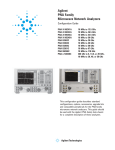
Agilent
PNA Series
Microwave Network Analyzer
Configuration Guide
E8364A 45 MHz to 50 GHz
System configuration summary
This summary lists the main components required
to form a basic measurement system. Options or
peripherals may be added to provide enhanced
measurement and data storage capability.
Full S-parameter measurements
❑ Agilent PNA Series microwave
network analyzer
❑ Test port cables, 50 ohms
❑ Calibration kit for applicable
connector type
This configuration guide describes standard configurations, options, accessories,
upgrade kits and compatible peripherals for the PNA Series microwave network
analyzer. This guide should be used with the Agilent PNA Series microwave
network analyzer, Technical Specifications for a complete description of this analyzer.
Ordering guide for PNA Series
network analyzers
This guide is intended to assist you in the ordering
process. Additional information and products (such as
calibration kits and cables) are described throughout
this document.
❑ Choose ONE and ONLY one
(Options are mutually exclusive)
❍ Choose any combination
Step 1: Choose a frequency range and number
of ports
(Must choose one and only one)
Step 6: Would you like a commercial calibration
certificate with test data?
❑ 300 kHz – 9 GHz, please refer to the RF PNA
Series Configuration Guide
(literature number 5980-1235E)
❑ 45 MHz – 50 GHz, continue to Step 2
❑ No
❑ Yes (Option UK6)
Step 7: Would you like an additional warranty for a
total of 5 years?
Step 2: Would you like extended power range?
❑ Yes (Option W50)
❑ Yes (Option UNL)
❑ No
❑ No (Standard power range)
Step 3: Would you like a configurable test set?
❑ Yes (Option 014)
❑ No (Standard test set)
Step 4: Would you like time domain analysis?
❑ Yes (Option 010)
❑ No
Step 5: Would you like any accessories for your network
analyzer?
❍ Rack mount kit with handles (Option 1CP)
❍ Rack mount kit without handles (Option 1CM)
2
Step 8: Would you like any additional
documentation for your network analyzer?
English CD-ROM comes standard
❍ Service documentation, assembly level
(Option 0BW)
❍ United States - English documentation set
(Option AVK)
❍ Germany - German localization (Option ABD)
❍ Spain - Spanish localization (Option ABE)
❍ France - French localization (Option ABF)
❍ Japan - Japanese localization (Option ABJ)
Agilent Microwave PNA Series
The microwave PNA Series is an integrated vector
network analyzer with frequency coverage from 45 MHz
to 50 GHz. It is equipped with a built-in LCD display,
hard and floppy disk drives, S-parameter test set and
synthesized source. The analyzer has two 50-ohm,
2.4-mm (f) test ports. Included with each instrument is
a mouse, keyboard, CD-ROM containing a copy of online
help and programming documentation, a mini parallelto-parallel adapter, and a three-year return-to-Agilent
service warranty.
❑ E8364A network analyzer, 45 MHz to 50 GHz
Options
❑ Option 010 time-domain capability
For viewing reflection and transmission
responses in time or distance domain.
❑ Option 014 configurable test set
With the configurable test set option, six front
panel access loops are provided. Three access loops
are for port one and three for port two. The loops
provide access to the signal path between (a) the
source output and the reference receiver, (b) the
source output and directional coupler thru and (c)
the coupled arm of the directional coupler and the
port receiver. This option provides the capability to
improve measurement sensitivity for measuring
low-level signals, to reverse the directional coupler to
achieve even more dynamic range or to add
components and other peripheral instruments for a
variety of measurement applications.
❑ Option 1CM rack mount kit
Adds a rack mount and rail kit for use
without handles
❑ Option 1CP rack mount kit
Adds a rack mount and rail kit for use with
previously supplied handles
❑ Option UNL Extended power range and bias tees
Adds two step attenuators and two bias tees.
A step attenuator and bias tee set is inserted
between the source and test port one and
another set between the source and test port two.
3
Documentation
Certification options
❑ Option AVK adds printed copy of Online Help and
programming documentation
❑ Option 0BW adds printed copy of assembly level
service manual
❑ Option UK6 Commercial calibration certificate with
test data
Localization
The following options provide a translated, printed
copy of Online Help and an English printed copy of
programming documentation.
❑ Option ABD German manual
❑ Option ABE Spanish manual
❑ Option ABF French manual
❑ Option ABJ Japanese manual
4
Service and support options
❑ Option W01 Converts 3-year return-to-Agilent
service warranty to 1-year on-site service
(check with your local Agilent sales or service office
for availability in your area)
❑ Option W31 Converts 3-year return-to-Agilent
service warranty to 3-year on-site service
(check with your local Agilent sales or service office
for availability in your area)
❑ Option W32 3-year return-to-Agilent
commercial calibration agreement
❑ Option W34 3-year return-to-Agilent
standards-compliant calibration agreement
❑ Option W50 Extends return-to-Agilent service
warranty to 5 years
❑ Option W51 Converts 3-year return-to-Agilent
service warranty to 5-year on-site service
(check with your local Agilent sales or service office
for availability in your area)
❑ Option W52 5-year return-to-Agilent
commercial calibration agreement
❑ Option W54 5-year return-to-Agilent
standards-compliant calibration agreement
Measurement accessories
A complete line of RF and microwave test accessories
can be found in the Agilent RF and Microwave Test
Accessories Catalog (literature number 5968-4314EN)
or by visiting www.agilent.com/find/mta
Accessories are available in these connector types:
50 ohm Type-N, 3.5 mm, 7 mm, 2.4 mm, 2.92 mm,
and waveguide. Test port cables and a calibration kit
should be added for a complete measurement system.
A verification kit is used to verify corrected system
performance.
Test-port cables
Test port cables are used to connect the network
analyzer to the device under test.
❑ 85133C single semi-rigid: 2.4 mm cable,
dc to 50 GHz
Includes one 81 cm (32 in) cable with female
connector
❑ 85133D semi-rigid: 2.4 mm cable set,
dc to 50 GHz
Includes two 53 cm (21 in) cables with male
and female connectors
❑ 85133E single flexible 2.4 mm cable, dc to 50 GHz
Includes one 113 cm (44 in) cable with a female
connector
❑ 85133F flexible 2.4 mm cable set, dc to 50 GHz
Includes two 72 cm (28 in) cables with male and
female connectors
Calibration kits
Mechanical calibration kits include standards, such
as open/short circuits and loads, which are measured
by the network analyzer for increased measurement
accuracy.
Choose a calibration kit for each connector type to
be used.
Economy, includes:
• open standards (male and female)
• short standards (male and female)
• fixed-termination standards (male and female)
• in-series adapters
Standard, includes the devices in the economy kit
and adds:
• sliding load standards (male and female)
Precision, includes the devices in the economy kit
and adds:
• 50 ohm airline(s) for TRL calibration
TRL adapters
5
For devices with 2.4 mm connectors
For devices with K connectors (2.92mm)
(see Adapters section for information about Agilent
2.4 mm adapters)
(see Adapters section for information about Agilent
2.92 mm adapters)
Mechanical calibration kits
Mechanical calibration kits
❑ 85056D economy: 45 MHz to 50 GHz. Includes:
00901-60003 2.4 mm (m) fixed broadband load
00902-60004 2.4 mm (f) fixed broadband load
85056-60005 2.4 mm (m) to 2.4 mm (m) adapter
85056-60006 2.4 mm (f) to 2.4 mm (f) adapter
85056-60007 2.4 mm (m) to 2.4 mm (f) adapter
85056-60020 2.4 mm (m) short
85056-60021 2.4 mm (f) short
85056-60022 2.4 mm (m) open
85056-60023 2.4 mm (f) open
❑ 85056K 2.92/2.4 economy: 45 MHz to 50 GHz.
Includes:
00901-60003 2.4 mm (m) fixed broadband load
00902-60004 2.4 mm (f) fixed broadband load
00915-60003 2.4 mm (m) sliding load (Option 001)
00915-60004 2.4 mm (f) sliding load (Option 001)
11904-60001 2.4 mm (m) to 2.92 mm (m) adapter
11904-60002 2.4 mm (f) to 2.92 mm (f) adapter
11904-60003 2.4 mm (m) to 2.92 mm (m) adapter
11904-60004 2.4 mm (f) to 2.92 mm (f) adapter
85056-60005 2.4 mm (m) to 2.4 mm (m) adapter
85056-60006 2.4 mm (f) to 2.4 mm (f) adapter
85056-60007 2.4 mm (m) to 2.4 mm (f) adapter
85056-60020 2.4 mm (m) short
85056-60021 2.4 mm (f) short
85056-60022 2.4 mm (m) open
85056-60023 2.4 mm (f) open
❑ 85056A standard: 45 MHz to 50 GHz. Includes:
00901-60003 2.4 mm (m) fixed broadband load
00902-60004 2.4 mm (f) fixed broadband load
00915-60003 2.4 mm (m) sliding load
00915-60004 2.4 mm (f) sliding load
85056-60005 2.4 mm (m) to 2.4 mm (m) adapter
85056-60006 2.4 mm (f) to 2.4 mm (f) adapter
85056-60007 2.4 mm (m) to 2.4 mm (f) adapter
85056-60020 2.4 mm (m) short
85056-60021 2.4 mm (f) short
85056-60022 2.4 mm (m) open
85056-60023 2.4 mm (f) open
6
For devices with 3.5 mm or SMA
connectors
(see Adapters section for information about the Agilent
3.5 mm adapters)
Mechanical calibration kits
❑ 85052D economy: 45 MHz to 26.5 GHz. Includes:
00902-60003 3.5 mm (m) fixed load
00902-60004 3.5 mm (f) fixed load
85052-60006 3.5 mm (m) short
85052-60007 3.5 mm (f) short
85052-60008 3.5 mm (m) open
85052-60009 3.5 mm (f) open
85052-60012 3.5 mm (f) to 3.5 mm (f) adapter
85052-60013 3.5 mm (f) to 3.5 mm (m) adapter
85052-60014 3.5 mm (m) to 3.5 mm (m) adapter
❑ 85052B standard: 45 MHz to 26.5 GHz. Includes:
00902-60003 3.5 mm (m) fixed load
00902-60004 3.5 mm (f) fixed load
00911-60019 3.5 mm (m) sliding load
00911-60020 3.5 mm (f) sliding load
85052-60006 3.5 mm (m) short
85052-60007 3.5 mm (f) short
85052-60008 3.5 mm (m) open
85052-60009 3.5 mm (f) open
85052-60012 3.5 mm (f) to 3.5 mm (f) adapter
85052-60013 3.5 mm (f) to 3.5 mm (m) adapter
85052-60014 3.5 mm (m) to 3.5 mm (m) adapter
❑ Option K11 PSC-3.5 slotless female center
contact repair kit
❑ 85052C precision TRL: 45 MHz to 26.5 GHz.
Includes:
00902-60003 3.5 mm (m) fixed load
00902-60004 3.5 mm (f) fixed load
85052-60006 3.5 mm (m) short
85052-60007 3.5 mm (f) short
85052-60008 3.5 mm (m) open
85052-60009 3.5 mm (f) open
85052-60032 3.5 mm (f) to 3.5 mm (f) adapter
85052-60033 3.5 mm (m) to 3.5 mm (m) adapter
85052-60034 3.5 mm (f) to 3.5 mm (m) adapter
85052-60035 3.5 mm short TRL line
85052-60036 3.5 mm long TRL line
For devices with Type-N connectors
(see Adapters section for information about Agilent
Type-N adapters)
Mechanical calibration kits
❑ 85054D economy: 45 MHz to 18 GHz. Includes:
85054-60025 Type-N (m) short
85054-60026 Type-N (f) short
85054-60027 Type-N (m) open
85054-60028 Type-N (f) open
85054-60031 Type-N (f) to 7mm adapter
85054-60032 Type-N (m) to 7mm adapter
85054-60037 Type-N (f) to Type-N (f) adapter
85054-60038 Type-N (m) to Type-N (m) adapter
85054-60046 Type-N (m) fixed load
85054-60047 Type-N (f) fixed load
❑ 85054B standard: 45 MHz to 18 GHz. Includes:
00909-60011 Type-N (m) fixed lowband load
00909-60012 Type-N (f) fixed lowband load
85054-60025 Type-N (m) short
85054-60026 Type-N (f) short
85054-60027 Type-N (m) open
85054-60028 Type-N (f) open
85054-60031 Type-N (f) to 7mm adapter
85054-60032 Type-N (m) to 7mm adapter
85054-60037 Type-N (f) to Type-N (f) adapter
85054-60038 Type-N (m) to Type-N (m) adapter
85054-80010 Type-N (f) sliding load
85054-80009 Type-N (m) sliding load
85054-60050 Type-N (f) connector gage
85054-60052 Type-N (f) gage master
85054-60051 Type-N (m) connector gage
85054-60053 Type-N (m) gage master
❑ Option K11 PSC-N slotless contact repair kit
7
For devices with 7 mm connectors
For devices with waveguide
(see Adapters section for information about Agilent
7 mm adapters)
(see Adapters section for information about Agilent
coax to waveguide adapters)
Mechanical calibration kits
Mechanical calibration kits
❑ 85050D economy: 45 MHz to 18 GHz. Includes:
85050-60006 7 mm fixed broadband load
85050-80007 7 mm short
85050-80010 7 mm open
X Band
❑ 85050B standard: 45 MHz to 18 GHz. Includes:
00909-60008 7 mm coax termination
85050-60006 7 mm fixed broadband load
85050-80007 7 mm short
85050-80010 7 mm open
85050-80011 7 mm sliding load
❑ 85050C precision TRL: 45 MHz to 18 GHz.
Includes:
00909-60008 7 mm coax termination
85050-60003 7 mm to 7 mm airline
85050-60005 7 mm to 7 mm TRL adapter
85050-60006 7 mm fixed broadband load
85050-80008 7 mm short
85050-80009 7 mm short collet
85050-80010 7 mm open
❑ X11644A standard, WR-90: 8.2 to 12.4 GHz.
Includes:
00896-60008 X-band standard section
00910-60003 X-band termination
11644-20018 X-band short
11644-20021 X-band shim
P Band
❑ P11644A standard, WR-62: 12.4 to 18 GHz.
Includes:
00896-60007 P-band standard section
00910-60002 P-band termination
11644-20017 P-band short
11644-20020 P-band shim
K Band
❑ K11644A standard, WR-42: 18 to 26.5 GHz.
Includes:
00896-60006 K-band standard section
00910-60001 K-band termination
11644-20016 K-band short
11644-20019 K-band shim
R Band
❑ R11644A standard, WR-28: 26.5 to 40 GHz.
Includes:
00914-20028 R-band termination
11644-20005 R-band short
11644-20003 R-band shim
11644-60001 R-band 10 cm straight waveguide
11644-60016 R-band 5 cm straight waveguide
Q Band
❑ Q11644A standard, WR-28: 26.5 to 40 GHz.
Includes:
11644-60005 Q-band termination
11644-20004 Q-band short
11644-20001 Q-band shim
11644-60002 Q-band 10 cm straight waveguide
11644-60017 Q-band 5 cm straight waveguide
8
Verification kits
All Agilent verification kits include:
• precision Zo airline
• mismatched airline
• fixed attenuators
• traceable measured data and uncertainties
❑ 85057B 45 MHz to 50 GHz 2.4 mm kit
Includes attenuators, airline and mismatch airline
with data on a 3.5-inch disk for use in confirming
accuracy enhanced system measurement performance, traceable to national standards. Test procedure
is provided in the service manual.
❑ 85055A 300 kHz to 18 GHz Type-N kit
Includes attenuators, airline and mismatch airline
with data on a 3.5-inch disk for use in confirming
accuracy enhanced system measurement performance, traceable to national standards. Test procedure
is provided in the service manual.
❑ 85053B 300 kHz to 26.5 GHz 3.5 mm kit
Includes attenuators, airline and mismatch airline
with data on a 3.5-inch disk for use in confirming
accuracy enhanced system measurement performance, traceable to national standards. Test procedure
is provided in the service manual.
❑ 85051B 300 kHz to 18 GHz 7 mm kit
Includes attenuators, airline and mismatch airline
with data on a 3.5-inch disk for use in confirming
accuracy enhanced system measurement performance, traceable to national standards. Test procedure
is provided in the service manual.
❑ R11645A 26.5 to 40 GHz R-Band W-28 kit
Includes attenuators and mismatch attenuator with
data on a 3.5-inch disk for use in confirming accuracy enhanced system measurement performance,
traceable to national standards. Test procedure is
provided in the service manual.
❑ Q11645A 33 to 50 GHz Q-Band W-22 kit
Includes attenuators and mismatch attenuator with
data on a 3.5-inch disk for use in confirming accuracy enhanced system measurement performance,
traceable to national standards. Test procedure is
provided in the service manual.
Adapters
❑
❑
❑
❑
11900A/B/C/D 2.4 mm adapters
11904A/B/C/D 2.4 mm to 2.92 mm adapters
11902A/B 2.4 mm to 3.5 mm adapters
11903A/B/C/D 2.4 mm to Type-N 50 ohm adapters
9
General accessories
USB Periferals
❑ N4688A CD-ROM drive
Provides an external read/write CD-ROM drive
with a USB cable.
❑ N4689A USB hub
Provides a USB hub for connecting additional
USB peripherals.
Probe
❑ 85024A high-frequency probe
Provides high-impedance in-circuit test capability
from 300 kHz to 3 GHz.
Power meters and sensors
Recommended for self support, adjustments and
performance tests to verify proper instrument
operation.
❑ E4418B single-channel power meter
❑ E4419B dual-channel power meter
❑ 8481B power sensor, 10 MHz to 18 GHz,
Type-N (m),25 W
❑ 8481A power sensor, 10 MHz to 18 GHz,
Type-N (m),100 mW
❑ 8485A power sensor, 50 MHz to 26.5 GHz,
APC-3.5 mm (m),100 mW
❑ 8487A power sensor, 50 MHz to 50 GHz,
2.4 mm,300 mW
❑ 8487D power sensor, 50 MHz to 50 GHz,
2.4 mm,100 mW
❑ R8486A power sensor, 26 GHz to 40 GHz,
waveguide flange UG-599/U,100 mW
❑ Q8486A power sensor, 33 GHz to 50 GHz,
waveguide flange UG-383/U,100 mW
❑ E4412A CW power sensor, 10 MHz to 18 GHz,
Type-N (m), 200 mW
1. The PNA Series analyzer is supplied with handles.
10
Amplifiers
❑ 83006A power amplifier, 10 MHz to 26.5 GHz,
20 dB gain, power out: +18 dBm to 10 GHz or
+16 dBm to 20 GHz or +14 dBm to 26.5 GHz
❑ 83017A power amplifier, 50 MHz to 26.5 GHz,
25 dB gain, power out: +20 dBm to 20 GHz, or
+15 dBm to 26.5 GHz
❑ 83018A power amplifier, 2 to 26.5 GHz, 27 dB
gain to 20 GHz or 23 dB to 26.5 GHz, power out:
+24 dBm to 20 GHz or +21 dBm to 26.5 GHz
❑ 83020A power amplifier, 2 to 26.5 GHz, 30 dB
gain to 20 GHz or 27 dB to 26.5 GHz, power out:
+30 dBm to 20 GHz or +26 dBm to 26.5 GHz
❑ 83050A power amplifier, 2 to 50 GHz, 23 dB gain,
power out: +20 dBm to 40 GHz or +17 dBm to 50 GHz
❑ 83051A power amplifier, 45 MHz to 50 GHz,
23 dB gain power out: +12 dBm to 45 GHz or
+10 dBm to 50 GHz
Couplers
❑ 87300B coaxial coupler, 1 to 20 GHz, SMA (f),
10 dB coupling
❑ 87300C coaxial coupler, 1 to 26.5 GHz, 3.5 mm
(f), 10 dB coupling
❑ 87301D coaxial coupler, 1 to 40 GHz, 2.4 mm (f)
or optional 2.92 mm (f), 13 dB coupling
❑ 87310B 90o coaxial coupler, 1 to 18 GHz, SMA
(f), 3 dB coupling
❑ 87301E coaxial coupler, 2 to 50 GHz, 2.4 mm (f),
10 dB coupling
Equipment racks and case
❑ Rack mount flange kit, for use with handles;
includes handles1
❑ Rack mount kit, for use without handles; may be
ordered as option 1CM
❑ Rack mount kit, for use with previously supplied
handles; may be ordered as option 1CP
❑ Rail kit, included with option 1CM and 1CP
Applications
Peripherals
Material measurement
The following peripherals may be used with the E8364A.
Other peripherals not listed here may also be compatible with these instruments.
❑ 85070D High-Temperature Dielectric Probe Kit
The 85070D allows the measurement of the
dielectric properties of materials quickly and
conveniently. Measurements made with this probe are
nondestructive and require no sample preparation.
The dielectric probe is well suited for measurements
of liquid, semisolid and flat solid materials.
Measurement results can be viewed in a variety of
formats (er’, e r “, tan d or Cole-Cole). The supplied
software can be run in the PNA analyzer or on a PC.
❑ 85071D Materials Measurement Software
The material software calculates the permittivity and
permeability of material samples placed in a coaxial
airline or a rectangular waveguide. The measurement technique works well for solid materials that
can be machined to fit precisely inside a transmission line. Measurement results can be viewed in a
variety of formats (er’, e r “, tan d, mr’, m r “,
tan dm or Cole-Cole). The software can be run in the
PNA analyzer or on a PC.
CD-ROM drive
USB-compatible CD-ROM drive
Monitors
VGA-compatible monitor
Printers
USB, LAN, parallel or serial printers with Microsoft ®
Windows ® 2000 printer driver
Interface cables
Choose the appropriate cables to connect each
peripheral to the network analyzer.
10833A GPIB cable, 1.0 m (3.3 ft)
10833B GPIB cable, 2.0 m (6.6 ft)
10833D GPIB cable, 0.5 m (1.6 ft)
Filter tuning
❑ N4261A Filter Tuning Software
This software will significantly reduce filter tuning
training times and increase manufacturing throughput. Through the graphical user interface, visual
training indicators show when the individual
resonators and couplers in a filter have been tuned
within specifications. The indicators also show the
user when and how to tune each filter element,
reducing the number of times each element has to
be retuned before the filter meets specifications.
11
Upgrade kits
Upgrade kits for the E8364A
Upgrade kits are available to add options after
initial purchase. To order an upgrade kit for an E8364A,
order the analyzer’s model number followed by a “U”,
then indicate the option to be added:
❑ Option 010 time-domain upgrade kit
The serial number of the E8364A to be retrofitted
must be specified when ordering this kit. Installation
is not included.
❑ Option 014 configurable test set upgrade kit
❑ Option 099 firmware upgrade
Provides the latest revision of firmware for the PNA
Series on CD-ROM. Firmware is user-installable.
Installation requires USB CD-ROM drive or external
computer connected via LAN. The latest firmware is
also available from our web site. Visit our web page
at: www.agilent.com/find/pna
❑ Option UNL Extended power range
Adds a step attenuators and a bias tee between
source and each test port.
Upgrades requiring model number changes are
addressed on a special handling quotation basis.
Contact your local Agilent sales or service office for
further information.
12
Additional services
The ease-of-use and performance of the PNA Series
vector network analyzers is only a small part of what
is available from Agilent. Contact your local Agilent
Sales or Support Desk regarding additional service
and support products available:
• Calibration services
• Repair services
• Technical consulting
• Process consulting
• Education and training
❑ W50 5-Year Extended Repair Coverage
Provides warranty-like repair coverage with
return-to-Agilent logistics for an additional 2-years
over the standard 3-year warranty that comes with
the hardware.
❑ W01 1-year on-site warranty conversion
Upfront option that converts 3-year return-to-Agilent
service warranty to 1-year on-site
❑ W31 3-year on-site warranty conversion
Upfront option that converts 3-year return-to-Agilent
service warranty to 3 years on-site.
❑ W51 5-year on-site warranty conversion
Upfront option that converts 3-year return-to-Agilent
service warranty to 5-years on-site.
❑ W32 3-Year Calibration Service
Upfront option that provides (return-to-Agilent)
standard calibrations based on manufacturer calibration cycles for the hardware over 3-year period.
❑ W34 3-Year Accredited Calibration Service
Upfront option that provides (return-to-Agilent)
accredited calibrations (premium documentation and
adjustment recording) based on manufacturer
calibration cycles for the hardware over 3-year period.
❑ W52 5-Year Calibration Service
Upfront option that provides (return-to-Agilent)
standard calibrations based on manufacturer calibration cycles for the hardware over 5-year period.
❑ W54 5-Year Accredited Calibration Service
Upfront option that provides (return-to-Agilent)
accredited calibrations (premium documentation
and adjustment recording) based on manufacturer
calibration cycles for the hardware over 5-year period.
For on-line information about Agilent’s service and
support products visit:
www.agilent.com/find/tm_services
13
Literature and information
PNA Series Brochure, literature number 5968-8472E
Microwave PNA Series Data Sheet, literature
number 5988-3992EN
Application and product notes
Application Development with the Agilent PNA Series
of Network Analyzers
literature number 5980-2666ENUS
Understanding and Improving Network Analyzer
Dynamic Range Application Note 1363-1
literature number 5980-2778EN
The “Need for Speed” in Component
Manufacturing Test
literature number 5980-2783EN
Connectivity Advances in a LAN-enabled Instrument
literature number 5980-2782EN
De-embedding and Embedding S-parameter
Networks Using the PNA Series Network Analyzer
Application Note 1364-1
literature number 5980-2784EN
Advanced Filter Tuning Using Time Domain
Application Note 1287-10
literature number 5980-2785EN
Understanding the Fundamental Principles of Vector
Network Analysis Application Note 1287-1
literature number 5965-7707E
Exploring the Architectures of Network Analyzers
Application Note 1287-2
literature number 5965-7708E
Applying Error Correction to Network Analyzer
Measurements Application Note 1287-3
literature number 5965-7709E
14
Network Analyzer Measurements: Filter and
Amplifier Examples Application Note 1287-4
literature number 5965-7710E
Improving Throughput in Network Analyzer
Applications Application Note 1287-5
literature number 5966-3317E
Using a Network Analyzer to Characterize
High-Power Components Application Note 1287-6
literature number 5966-3319E
Simplified Filter Tuning Using Time-Domain Analysis
Application Note 1287-8
literature number 5968-5328E
In-Fixture Measurements Using Vector Network
Analyzers Application Note 1287-9
literature number 5968-5329E
10 Hints for Making Better Network Analyzer
Measurements Application Note 1291-1
literature number 5965-8166E
Key web resources
Visit our component manufacturer industry
area at:
www.agilent.com/find/component_test
Visit the PNA Series home page at:
www.agilent.com/find/pna
Most application and product notes may be downloaded
from our web site at:
www.agilent.com/find/tmappnotes/apps
15
Agilent Technologies’ Test and Measurement Support, Services,
and Assistance
Agilent Technologies aims to maximize the value you receive, while
minimizing your risk and problems. We strive to ensure that you get
the test and measurement capabilities you paid for and obtain the
support you need. Our extensive support resources and services
can help you choose the right Agilent products for your applications
and apply them successfully. Every instrument and system we sell
has a global warranty. Support is available for at least five years
beyond the production life of the product. Two concepts underlie
Agilent's overall support policy: "Our Promise" and "Your
Advantage."
Our Promise
Our Promise means your Agilent test and measurement equipment
will meet its advertised performance and functionality. When you
are choosing new equipment, we will help you with product information, including realistic performance specifications and practical
recommendations from experienced test engineers. When you use
Agilent equipment, we can verify that it works properly, help with
product operation, and provide basic measurement assistance for
the use of specified capabilities, at no extra cost upon request.
Many self-help tools are available.
Your Advantage
Your Advantage means that Agilent offers a wide range of additional expert test and measurement services, which you can purchase
according to your unique technical and business needs. Solve problems efficiently and gain a competitive edge by contracting with us
for calibration, extra-cost upgrades, out-of-warranty repairs, and onsite education and training, as well as design, system integration,
project management, and other professional engineering services.
Experienced Agilent engineers and technicians worldwide can help
you maximize your productivity, optimize the return on investment
of your Agilent instruments and systems, and obtain dependable
measurement accuracy for the life of those products.
Microsft ® and Windows ® are U.S. registered trademarks of Microsoft Corporation.
By internet, phone, or fax, get assistance with all your test and
measurement needs.
Online assistance:
www.agilent.com/find/assist
Phone or Fax
United States:
(tel) 1 800 452 4844
Canada:
(tel) 1 877 894 4414
(fax) (905) 282-6495
China:
(tel) 800-810-0189
(fax) 1-0800-650-0121
Europe:
(tel) (31 20) 547 2323
(fax) (31 20) 547 2390
Japan:
(tel) (81) 426 56 7832
(fax) (81) 426 56 7840
Korea:
(tel) (82-2) 2004-5004
(fax) (82-2) 2004-5115
Latin America:
(tel) (305) 269 7500
(fax) (305) 269 7599
Taiwan:
(tel) 080-004-7866
(fax) (886-2) 2545-6723
Other Asia Pacific Countries:
(tel) (65) 375-8100
(fax) (65) 836-0252
Email: [email protected]
Product specifications and descriptions in this document subject to change without notice.
Copyright © 2001
Agilent Technologies, Inc.
Printed in USA, November 1 2001
5988-3993EN