1
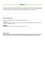
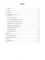
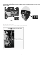
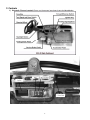
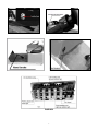
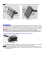
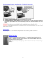
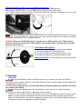
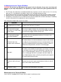
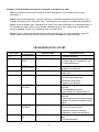
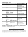
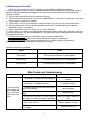
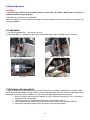
citEcar Street Legal Golf Cart
Owner’s Manual
Sold and Distributed by
citEcar LLC
www.citEcarEV.com
Phone: (866) 542-8677
Fax: (843) 556-4080
1
Preface
Thanks for purchasing a citEcar electric vehicle. This manual contains information for proper operating,
maintaining and caring of your electric vehicle. A thorough understanding of this manual will help you to obtain
maximum enjoyment from this electric vehicle. Please keep it properly stored for future reference.
Important Information:
Particularly important information is distinguished by the following notations:
WARNING!
Failure to follow Warning instructions could result in severe injury to the vehicle occupants, bystanders or persons
inspecting or repairing the vehicle.
CAUTION!
Failure to follow Caution instructions could cause damage to the vehicle.
Special Notices:
Because the seat & backrest wrapping film may stick to the seat vinyl and cause seat vinyl to
become stained, please remove the seat & backrest wrapping film when you receive the vehicle.
2
INDEX
1. Overview…………………………………………………………………………………………….4
2.
Controls……………………………………………………………………………………………..6
3.
Operations…………………………………………………………………………………..…….11
4.
Safe Operation Instructions…………………………… ……………………………………....12
5.
Maintenance ................................................................................................................... 13
5.1 Maintenance of Battery ............................................................................................. 13
5.2 Operation and Maintenance of Charger .................................................................... 17
5.3 Maintenance of the Traction Motor ............................................................................ 18
5.4 Maintenance of the Speed Controller: ....................................................................... 19
5.5 Diagnostics and Troubleshooting .............................................................................. 19
5.6 Maintenance of Rear Axle: ........................................................................................ 13
5.7 Wheel Replacement.................................................................................................. 23
5.8 Brake Adjustment ...................................................................................................... 24
6. Lubrication ......................................................................................................................... 24
7. Running-in of New Vehicle ................................................................................................. 24
8. Periodic Maintenance Charts ............................................................................................. 25
9. Storage .............................................................................................................................. 26
10. Wiring Diagram .............................................................................................................. 26
3
1. OVERVIEW
Our vehicle is environmental friendly, and it can be used as a people mover or utility car at a golf course, resort
hotels, private residential areas, tourist scenic spots, or any other places where allowed.
WARNING!
Please, always be sure of any restrictions in the area where you intend to use the vehicle to avoid any
unpleasant experiences.
IMPORTANT LABELS
SAFETY LABEL
Please read carefully and understand the contents on the safety label attached on the vehicle.
Label Above is attached on the dash panel as below:
4
Vehicle Information (Name Plate)
The name plate is either at the lower part of the dashboard as below Fig.2 shows or at the back of the front seat as
below Fig.1 shows:
Fig.1
Fig. 2
Chassis number of the vehicle
The position where the chassis number is located as per the picture below.
5
2. Controls
1) Schematic Figure of controls Please see the general overview of your dashboard below.
6
FUSE BOX
7
2)
Functions of Controls
Ignition key
The ignition key is used to switch on the electrical system of the vehicle.
To engage the motor and start the vehicle: Insert the key and turn it clockwise to the “ON”
position, at the same time, the 12V accessory system (including the headlight, turn signal,
taillight, brake light and horns) will be engaged also.
To switch the power off, turn the key counterclockwise to “OFF” position.
CAUTION!
When the Key is on “ON” position, the key cannot be pulled out. Do Not try to pull out the
Key when it’s on “ON” position!
Forward/Reverse switch
This is a three-position switch, pressing the upper part gets the vehicle moving forwards
while pressing the lower part gets the vehicle moving backwards, and the middle is neutral.
WARNING! This switch must be fully pressed into the proper position, or the electric
system and motor will be damaged.
NOTE: The buzzer will beep when the lower part of this switch is depressed, to warn any
people around your vehicle.
Accelerator pedal
The accelerator pedal is used to control the speed when driving. Push it down slowly to
increase the speed. The vehicle will speed up with the gradual stepping down on the
accelerator pedal, eventually reaching the full speed when the pedal is stepped down to
the bottom. The vehicle slows down with the lifting of the pedal. When the pedal is fully
lifted, the electric brake will start to work, and the vehicle will stop.
Service Brake pedal
The service brake pedal is used for braking. The shapes of the service brake pedal of the
mechanical brake system and hydraulic brake system are different. Please have a look
at the picture of those two types of service brake pedals below (refer to pictures of ‘Mechanical Brake’ and
‘Hydraulic Brake’).
8
NOTE: On the mechanical brake system, the service brake pedal is combined with the parking brake pedal.
Mechanical Brake
Hydraulic Brake
Parking Brake Pedal
The parking brake is used for braking while parking. The parking brake of the mechanical brake system is different
from hydraulic brake system. The parking brake of the mechanical brake system is engaged by your foot as
shown in above picture (refer to ‘Mechanical Brake’). The parking brake of the hydraulic brake system is engaged
by your hand as shown in the picture below (refer to ‘Hand Brake’). The parking brake should be engaged into
parking position whenever the vehicle is left unattended. Never drive with the parking brake engaged.
WARNING!
The foot parking brake will automatically release when the accelerator pedal is stepped down. If the power
key is in “ON” position, stepping down the accelerator pedal may suddenly cause the vehicle to move.
How to engage and disengage the parking brake – For Mechanical Brake System
To engage the parking brake - step down the service brake pedal to the end by lower parts of the foot and
then press down the parking brake pedal by the upper parts of the foot until it’s hooked;
NOTE: If the parking brake pedal fails to be locked in the lock position, please repeat above procedure until it is
locked.
• To disengage the parking brake - step down the service brake pedal to the end until the parking brake pedal
is unhooked (released).
•
9
How to engage and disengage the parking brake – For Hydraulic brake system
•
•
To engage the hand parking brake, pull up the hand brake lever to the end.
To disengage the hand parking brake, pull up the hand brake lever to the end and then press down the
button on the top of the brake lever, with the button being pressed down, push down the brake lever to the
bottom.
WARNING! Please always release the brake handle completely before you drive the vehicle.
WARNING! Do not step down on both the brake pedal and the accelerator pedal at the same time, this will
badly damage the motor.
Steering wheel
The steering wheel is used to control the driving direction. Please avoid any sudden and wild turns.
Battery Power Meter
There are 10 divisions on the meter (from 0 to 1). The meter will decline from the top to the
bottom as the battery discharges. When the battery is too low, the red indicator light will flash,
reminding you to recharge the battery.
NOTE: please refer to your Battery Chargers Owner Manual for information on how to recharge
the batteries.
10
TOW/RUN SWITCH (available for Curtis 1266 and 1268 controller)
Before operating the vehicle, make sure the TOW/RUN switch is in the “RUN” position.
Make sure the TOW/RUN switch is on the “TOW” position if towing or pushing the vehicle.
The TOW/RUN switch is located under the seat on the passenger side, either on the controller cover or just under
the rear body as shown in the picture below.
NOTE: When the TOW/RUN switch is on the “RUN” position, the vehicle will beep when you push the vehicle to
remind you. Pushing or towing the vehicle while in the “RUN” position will burn up the motor and electrical
components of your vehicle. This is a major fire hazard.
WARNING! Whenever the TOW/RUN switch is moved from the “RUN” position to the “TOW” position,
please be sure to move it back to the “RUN” position, there will be a delay of approximately 30 seconds
before the vehicle will run.
TURN SIGNAL/HORN SWITCH
This switch is used to switch the turn signal and horn on/off.
1) Pull back the handle lever to activate the horn.
2) Push up the handle lever to activate the right turn signal.
3) Pull down the handle lever to activate the left turn signal.
HEADLIGHT SWITCH Pull out the button on the right side to switch
on the headlight.
3. Operation
STARTING:
a) With the Forward/Reverse switch in the Neutral position, turn the power key to the “ON” position.
CAUTION!
The car will not run if you press down the F/R switch to Forward or Reverse position before turning the power key,
if equipped with AC power system.
WARNING! Do not step down the accelerator pedal when turning on the power key, otherwise, the vehicle
may suddenly start moving.
b) With the park brake applied, press the Forward/Reverse switch and lock it in the desired position.
CAUTION!
Do not shift from Forward
to Reverse
while the vehicle is moving.
c) Make sure that your path is clear in your direction. If the vehicle is equipped with mechanical brake system,
depress the lower section of the brake pedal to release the park brake, slowly step down the accelerator
pedal, it will start to move. If the vehicle is equipped with hydraulic brake system with hand brake, release the
hand brake first before you step down the accelerator pedal.
↑
↓
11
CAUTION!
If the vehicle is equipped with the mechanical brake system, depressing the accelerator pedal will release the
parking brake if it’s engaged. Depressing the accelerator pedal is not the preferred method of releasing the
parking brake. Depressing the lower section of the brake pedal is the preferred method of releasing the parking
brake to assure the longest service life of brake components. If the key switch is “ON” and the parking brake is set,
depressing the accelerator will release the parking brake and cause the vehicle to move which could cause severe
injury or death.
CAUTION:
If the accelerator pedal is stepped down before the power key is on, the vehicle will not run. In this case,
you should release the accelerator pedal first, and then turn the power key “ON”, then step down the
accelerator pedal again, the vehicle will start moving.
STOPPING:
To stop the vehicle, gradually press down the brake pedal. When the vehicle has come to a stop, apply the parking
brake pedal and turn the power key to “OFF” and press the F/R switch on Neutral position.
CAUTION:
Do not hold the vehicle on an incline with the accelerator, please use the brake.
4. SAFE OPERATION INSTRUCTIONS
Our electric vehicle is designed for simple operation. However, please make sure to observe the following safe
operation instructions:
BEFORE OPERATING THE VEHICLE:
ALWAYS read these instructions first before you start driving the vehicle.
ONLY authorized people should drive this vehicle, and from the driver’s side ONLY.
Do not drive this vehicle on any public road before it is registered and has the license place attached.
ONLY drive the vehicle in areas where allowed to be used by law or local regulations and the conditions are
safe to do so.
DO NOT allow more than the designated amount of people on the vehicle.
DO NOT overload the vehicle in any case, otherwise the motor may be damaged. The vehicle may also lose
control and/or the driver and passengers will be put in danger.
DO NOT operate the vehicle while under the influence of alcohol or drugs, otherwise, their effect on vision
and judgment will put the driver and passenger(s) in danger.
DO NOT make the vehicle climb any slope beyond its grade ability.
DO NOT overtake other vehicles at crossroads, in blind areas or in any dangerous conditions.
Always fasten the safety belt properly before the vehicle moves under the following instructions:
1) Be certain the seat belts are latched securely and are free from any twists.
2) Position the shoulder belt across the top of the shoulder. Do not place the shoulder belt under an arm.
3) Loose fitting safety belts significantly reduce protection. Keep belts snug and positioned low on the hips.
4) Do not exceed the recommended number of occupants for the vehicle.
5) Bench seats are designed for two occupants only.
WHILE OPERATING THE VEHICLE
Keep your entire body inside the vehicle, keep seated and hold on while the vehicle is moving.
Do not start the vehicle until all occupants are securely seated.
Keep your hands on the steering wheel and your eyes on the path you are going.
Always back up slowly, and watch the back carefully.
Avoid starting or stopping suddenly.
Avoid turning the steering wheel too sharply at high speed.
Always drive slowly up or down any incline.
Do not make any modifications or additions which may affect the capacity or safety of the vehicle.
Children are not allowed to play in the vehicle. Children should be seated between adults and protected by them
when the vehicle is moving.
12
5. Maintenance
Users should perform regular maintenance to ensure the vehicle is in good performance.
5.1 Maintenance of the Batteries
NOTE: Our standard vehicles are equipped with deep-cycle flooded lead-acid batteries. If your vehicle is
equipped with any other types of batteries, please follow the maintenance instruction by the battery
manufacturer. Below maintenance instruction is especially for deep-cycle flooded lead-acid battery.
WARNING! Battery electrolyte is poisonous and dangerous, and may cause severe burns, injury, and etc.
Always wear protective clothing, gloves, and goggles when handling batteries, electrolyte, and charging
your battery.
KEEP OUT THE REACH OF CHILDREN.
1) CLEANING
a. The exterior of the battery, the connection wires and bolts should always be kept clean and dry. When
cleaning, please make sure all vent caps are tightly in place. Clean the battery top with a cloth or brush
and solution of baking soda and water. When cleaning, do not allow any cleaning solution, or other foreign
matter to get inside of the battery. This should be done every week.
b. Clean battery terminals and the inside of cable clamps using a post and clamp cleaner. Clean terminals
will have a bright metallic shine. This should be done when it is necessary.
c. Reconnect the clamps to the terminals and thinly coat them with petroleum jelly (Vaseline) to prevent
corrosion.
WARNING! Before you disconnect any battery cable from any terminal on the battery, please always remove the
power by disconnecting the main battery cable from the controller.
2) CHECKING THE TERMINALS AND NUTS
The connection of the battery should always be kept in good condition. Please check every week on whether any
battery cable terminals or nuts have become loose in order to prevent any spark or damage to terminals. Please
check every week whether any battery cable is damaged or not, any damaged battery cable should be replaced
immediately.
3) NO FOREIGN MATTER
Do not place any objects on the battery and do not connect the positive pole to the negative pole. This may cause
a short circuit, dangerous spark or may cause damage to the battery or injury to the user.
4) RECHARGING
a. As long as you use the vehicle, regardless of how long you have used it, the battery should be recharged
fully on the same day. Any delay on the re-charging will cause a negative effect on the battery. Note: the lead-acid
battery does not develop a memory, so it doesn’t need to be fully discharged before recharging.
b. If the vehicle is going to be unused for a long time, the battery should be fully recharged first. After that, the
battery should be fully recharged every 2 weeks or better yet, leave the charger plugged in.
c. When driving, the driver shall be always aware of the drop level of the battery power from the battery power
meter, any drop means the battery power is diminishing. Besides, the driver should estimate the distance needed
to be taken, and recharge the battery at a proper time in case that the vehicle cannot get back to the recharging
station in time for recharging.
WARNING! Please make sure the battery is recharged before the battery power meter shows only 20% is left. An
over-discharged battery will have a very short service life and will make the recharging very difficult.
WARNING! During recharging, the vehicle shall be parked in a well-ventilated area with filling caps tightly secured.
Keep far away from any flame and sparks to avoid any explosion or fire that could cause physical injury or
damage to the property.
WARNING! In summer time, when the battery is hot, do not recharge the battery immediately. Only charge the
battery when it cools down. And also do not charge the battery in the sunshine.
WARNING! In winter time, when the temperature is too low, charge the battery in a warm place.
WARNING! At the end of the battery’s life, its capacity will decrease dramatically. When changing a new group of
batteries, use the batteries of same brand, same model, same capacity and similar voltage (any difference should
be less than 0.02V). Equalizing charging is requested for the new group of batteries.
13
5) WATERING
Flooded batteries need distilled water. What’s more, watering must be done at the right time and in the right
amount or else the battery’s performance and longevity suffers.
Distilled water should always be added after fully charging. Prior to charging, there should be enough water to
cover the plates. If the battery has been discharged (partially or fully), the water level should also be above the
plates. Keeping the water at the correct level after a full charge, means you will not have to worry about the water
level at a different state of charge.
Depending on the local climate, charging methods, and application, etc., Trojan recommends that the batteries be
checked once a month until you get a feeling for how thirsty your batteries are.
Important things to remember:
1. Do not let the plates get exposed in the air. This will damage (corrode) the plates.
2. Do not fill the water to the cap. This most likely will cause the battery to overflow acid, consequently losing
capacity and causing a corrosive mess.
3. Do not use water with a high mineral content. Use distilled water only.
CAUTION:
The electrolyte is a solution of acid and water so skin contact should be avoided.
Step by step watering procedure:
1. Open the vent caps and look inside the filling wells.
2. Check the electrolyte level; the minimum level is at the top of the plates.
3. If necessary, add just enough water to cover the plates once.
4. Put batteries on a complete charge before adding water (refer to the Charging section).
5. Once charging is completed, open the vent caps and look inside the fill wells.
6. Add water until the electrolyte level is 1/8" below the bottom of the fill well.
7. A piece of rubber can safely be used as a dipstick to help determine the water level.
8. Clean, replace, and tighten all vent caps.
WARNING! Never add acid into the battery.
6) TESTING
Visual inspection alone is not sufficient to determine the overall health of the battery. Both open-circuit voltage and
specific gravity readings can give a good indication of the battery's charge level, life span, and health. Routine
voltage and gravity checks will not only show the state of charge but also help spot signs of improper care, such
as undercharging and over-watering, and possibly even locating a bad or weak battery. The following steps outline
how to properly perform routine voltage and specific gravity testing on batteries.
I. Specific Gravity Test (Flooded batteries only)
1. Do not add water.
2. Fill and drain the hydrometer 2 to 4 times before pulling out a sample.
3. There should be enough sample electrolyte in the hydrometer to completely support the float.
4. Take a reading, record, and return the electrolyte back to the cell.
5. To check another cell, repeat the 3 steps above.
6. Check all cells in the battery.
7. Replace the vent caps and wipe off any electrolyte that might have been spilled.
8. Correct the readings to 80o F: Add .004 to readings for every 10o above 80o F, Subtract .004 for every 10o below
80o F.
9. Compare the readings.
10. Check the state of charge using Table 1 shown on next page.
14
•
The readings should be at or above the factory specification of 1.277 +/- .007. If any specific gravity readings
register low, then follow the steps below.
1. Check and record voltage level(s).
2. Put battery(s) on a complete charge.
3. Take specific gravity readings again.
•
If any specific gravity readings still register low then follow the steps below.
1. Check voltage level(s).
2. Perform equalization charge. Refer to the Equalizing section for the proper procedure.
3. Take specific gravity readings again.
•
If any specific gravity reading still registers lower than the factory specification of 1.277+/- .007 then one or
more of the following conditions may exist:
1. The battery is old and approaching the end of its life.
2. The battery was left in a state of discharge too long.
3. Electrolyte was lost due to spillage or overflow.
4. A weak or bad cell is developing.
5. Battery was watered excessively previous to testing.
Batteries in conditions 1 - 4 should be taken to a specialist for further evaluation or retired from service.
II. Open-Circuit Voltage Test
For accurate voltage readings, batteries must remain idle (no charging, no discharging) for at least 6hrs,
preferably 24 hrs.
1. Disconnect all loads from the batteries.
2. Measure the voltage by a DC voltmeter.
3. Check the state of charge with Table 1.
4. Charge the battery if it registers 0% to 70% charged.
If the battery value is lower than that in Table 1, the following conditions may exist:
1. The Battery was left in a state of discharge too long.
2. The Battery has a bad cell.
Batteries in these conditions should be taken to a specialist for further evaluation or retired from service.
15
TABLE 1. State of charge as related to specific gravity and open circuit voltage
Percentage of Charge
Open-Circuit Voltage
Specific Gravity
Corrected to
80o F
6V
8V
12V
24V
36V
48V
100
1.277
6.37
8.49
12.73
25.46
38.20
50.93
90
1.258
6.31
8.41
12.62
25.24
37.85
50.47
80
1.238
6.25
8.33
12.50
25.00
37.49
49.99
70
1.217
6.19
8.25
12.37
24.74
37.12
49.49
60
1.195
6.12
8.16
12.24
24.48
36.72
48.96
50
1.172
6.05
8.07
12.10
24.20
36.31
48.41
40
1.148
5.98
7.97
11.96
23.92
35.87
47.83
30
1.124
5.91
7.88
11.81
23.63
35.44
47.26
20
1.098
5.83
7.77
11.66
23.32
34.97
46.63
10
1.073
5.75
7.67
11.51
23.02
34.52
46.03
7) BATTERY INSTALLATION
WARNING!
When working with the battery, DO NOT put wrenches or any other metal objects across the battery
terminals, otherwise, an arc can occur, and it may cause explosion of the battery and physical injury.
Battery is to be installed or replaced only by a qualified technician.
8) BATTERY CHARGING
NOTE: The Standard charger on the vehicle is an onboard one. It’s either installed in the rear bag well, or under
the seat or under the front body. Sometimes, based upon a dealer’s special request, the charger may not be
installed on the vehicle. Please always consult with the seller regarding the position of the charger. When it’s an
onboard charger, a separate charging cord will be provided with the vehicle for connecting the charger and AC
electricity. Charge the vehicle fully before your first use.
WARNING! Before you use the charger, please read the operation manual provided with the charger.
WARNING! Explosive hydrogen gas is produced while the battery is charging. Only charge the battery in
well-ventilated areas.
WARNING! Before using the charger, please check to see if the battery charger you are getting is correctly rated
as per your local AC electricity network.
WARNING! When using a new battery, make sure the new battery is per the same specifications as the original
one and is appropriate in application.
Following are the charging steps:
• Turn the power key to “OFF”.
• Connect the plug to the vehicle receptacle first; then connect it to your local AC power outlet.
WARNING! Do not disconnect the cord from the battery receptacle when the charger is ON, otherwise an arc
could occur which, may cause an explosion. Always disconnect the battery receptacle first, then disconnect from
the AC power outlet. The charger will turn off automatically when the battery is charged fully.
16
WARNING!
The battery receptacle is combined with a security switch which can cut off the power of the vehicle when the
battery is being charged, so the vehicle cannot be started as long as the battery receptacle is plugged in.
1) After the charger turns off, disconnect the plug on the AC charging cable from the AC power outlet first, and
then disconnect the cord from the vehicle receptacle.
2) It is prohibited to open the housing of the charger.
3) Only a qualified technician is allowed to open the housing of the charger.
4) The charger should be stored in a safe and dry room with good ventilation.
5) The charger should be packed properly if not used for a long time.
6) Read the operation manual for the charger carefully, follow all detailed operation instructions.
Equalizing charge
Equalizing is an over-charge performed on flooded lead acid batteries after they have been fully charged. It
reverses the buildup of negative chemical effects like stratification, a condition where acid concentration is greater
at the bottom of the battery than at the top. Equalizing also helps to remove sulfate crystals that might have built
up on the plates. If left unchecked, this build-up which is called Sulfation, will reduce the overall capacity of the
battery.
The charger will automatically start the equalizing charge after 30 times of charging, if it remains connected from
the grid and battery after the battery is charged fully.
Equalizing is recommended when low or wide ranging specific gravity (+/- .015) is detected after fully charging a
battery.
5.2 Operation and Maintenance of Charger
Note: As standard configuration, the charger is built in the vehicle; in some cases, it may not be built in the vehicle.
If it’s built in the vehicle, the position of the charger is either under the front seat or the bag well.
The procedure to use the charger (when the charger is built-in on the vehicle):
1. Connect the cord to the receptacle on the vehicle (if not already attached);
2. Connect the cord to the receptacle to the outlet of household grid.
3. After the charger cord is connected, the red indicator on the charger will flash, the charger starts the procedure
of self-inspection, after self-inspection, the green indicator flashes, and the charger starts to charge the
batteries.
4. When battery capacity is less than 80%, the green indicator flashes slowly; when battery capacity is more than
80%, the green indicator flashes fast; when the battery is fully charged, the green indicator will stop flash and
always be on, and the charger will stop charging automatically.
Note: This charger has the function of over-discharging protection to protect the battery from over-discharging.
When the battery is close to the charging point, it will reduce the discharging current from the battery to reduce the
speed of the vehicle, if it fails to charge the battery, it will cut the current from the battery and stop the vehicle to
force the user to charge the battery.
Note: When the grid voltage is out of range of 90-260V, the charger will stop charging to protect itself, at the same
time, the failure code light will be on to remind users. When the voltage returns back the requested voltage range
of 90-260V, it will automatically start to charge.
Note: The charger will automatically start equalizing charge after 30 times of charging if it remains connected from
the grid and battery after the battery is charged fully.
CAUTION - Charger is not allowed to be used if it gets wet.
CAUTION - Use the charger when the environment temperature is between -10℃ to +45℃ Celsius Degree
WARNING!
Only a qualified technician is allowed to open the housing of the charger
WARNING!
When charging the batteries, hydrogen will be generated, so it’s important to keep the charging area in a safe and
dry room with good ventilation, and also to avoid any fire and spark.
17
5.3 Maintenance of the Traction DC Motor
WARNING! Be sure there are NO explosive gas vapors in the air, otherwise, it may cause serve injury and
damage to your body and property if the explosive gas vapor contacts the sparks generated from the
motor.
1) For DC motor, the carbon brush should be checked every 3 months to see if it is worn or not, as it is an easily
worn part. If it is not replaced in time before it wears out, it will badly damage the motor.
2) Do not keep the motor running idly for long periods of time. Any idle running of the motor should be avoided.
3) Removal of mud, sand and other clinging objects shall be done frequently to help keep it from overheating.
4) Periodically use low pressure air to remove the dust from the carbon brush and the commutator. Periodically
check the connection of the carbon brush and the commutator.
Main malfunction and possible reason of DC motor
Item
Possible Causes
Symptoms
1
All copper plates turn black.
The pressure of the brush is incorrect.
2
The commutating copper
turns black in a certain order
and in groups.
Short circuit happens between the commutating copper or among
the armature coil; poor welding or disconnection happens between
the commutating copper and the armature coil.
3
The commutating copper
turns black disorderly.
The central line of the commutator deviates or its surface is not
round and not smooth.
The brush wears out,
changes colors and breaks.
The motor vibrates; the clearance between the brush and its holder
is too big; the clearance between the brush and commutator is too
big; the mica between different commutators extrudes; the brush is
made of the wrong materials; the brush is the wrong type.
Big spark
The motor is over-loaded; the commutators are not clean, not round
or not smooth; mica or some of the commutator is coming out; the
brush is not ground properly; the brush has a lot of pressure; the
brush is wrong type; the brush is jammed in the brush holder; the
brush holder becomes loose or vibrating; the polarity and sequence
of magnetic poles become wrong.
The brush and its wires get
hot.
Big spark from the brush; poor contact between the brush and soft
wires; small section area of soft wires.
The brush is noisy
The surface of the commutator is not smooth.
4
5
6
7
Maintenance of the Traction AC Motor
If your vehicle is equipped with AC motor, then the motor is maintenance free!
18
5.4 Maintenance of the Speed Controller
CAUTION
Only a qualified electrician is allowed to do the maintenance for the controller.
WARNING!
There are no spare parts available inside the controller. No attempt should be made to open, repair, or
otherwise modify the controller. Doing so may damage the controller and will void the warranty.
Cleaning
It is recommended that the controller be kept clean and dry and that its fault history file be checked and cleared
periodically.
Periodically cleaning the controller exterior will help protect it against corrosion and possible electrical control
problems created by the dirt, grime, and chemicals that are part of the operating environment and that normally
exist in battery powered systems.
Please use the following cleaning procedure for routine maintenance:
1) Turn the power key to OFF position.
2) Remove power by disconnecting the battery.
3) Discharge the capacitors in the controller by connecting a load (such as a contactor coil or a horn) across the
controller’s B+ and B- terminals.
4) Remove any dirt or corrosion from the connector areas. The controller should be wiped clean with moist rag.
Dry it before reconnecting the battery. The controller should not be subjected to pressured water flow from
either a standard hose or a power washer.
5) Make sure the connections are tight, but do not over tighten them.
Faulty History File
The handheld programmer (purchased separately) can be used to access the controller’s fault history file. The
programmer will read out all the faults the controller has experienced since the last time the history file was
cleared. Faults such as contactor faults may be the result of loose wires; contactor wiring should be carefully
checked. Faults such as high temperature may be caused by operator habits or by overloading.
After a problem has been diagnosed and corrected, it is a good idea to clear the fault history file. This allows the
controller to accumulate a new file of faults. By checking the new history file at a later date, you can readily
determine whether the problem was in deed fixed.
Or checking the problems according to the flashing of the STATUS light on the top of the controller. Please refer
to the details mentioned in our service manual which is available separately.
Please contact your local dealer or a qualified technician/electrician to work on the problems related to
the motor, controller or electrical system of the vehicle when you are not able to fix them.
5.5 Diagnostics and Troubleshooting
The 1268 controller provides diagnostics information to assist technicians in troubleshooting the drive system
problems. This information is displayed on the handheld programmer (or PC Programming Station), and it is also
available in the form of fault codes issued by the controller’s built-in Status LED and the optional remote LED
driven by the controller’s external LED output. Refer to the troubleshooting chart for suggestions covering a wide
range of possible faults.
PROGRAMMER DIAGNOSTICS
The programmer presents complete diagnostic information in plain language. Faults are displayed in the Faults
menu (see column 2 in the Troubleshooting Chart), and the status of the controller inputs/outputs is displayed in
the Monitor Menu.
Accessing the Fault History menu provides a list of the faults that have occurred since the fault history file was last
cleared. Checking (and clearing) the fault history file is recommended each time the vehicle is brought in for
maintenance.
The following 4-step process is recommended for diagnosing and troubleshooting an inoperative vehicle: (1)
visually inspect the vehicle for obvious problems; (2) diagnose the problem, using the programmer; (3) test the
circuitry with the programmer; and (4) correct the problem. Repeat the last three steps as necessary until the
vehicle is operational.
19
Example: A vehicle that does not operate in “forward” is brought in for repair.
Step 1: Examine the vehicle and its wiring for any obvious problems, such as broken wires or loose
connections.
Step 2: Connect the programmer, select the Faults menu, and read the displayed fault information. In this
example, the display shows “No Known Faults,” indicating that the controller has not detected any problems.
Step 3: Select the Monitor menu, and observe the status of the inputs and outputs in the forward direction. In
this example, the display shows that the forward switch did not close when “forward” was selected, which
means the problem is either in the forward switch or the switch wiring.
Step 4: Check or replace the forward switch and wiring and repeat the test. If the programmer shows the
forward switch closing and the vehicle now drives normally, the problem has been corrected.
TROUBLESHOOTING CHART
LED CODE
1,1
1,2
PROGRAMMER
LCD DISPLAY
HW FAILSAFE
THROTTLE
FAULT 1
EXPLANATION
Self-test or watchdog fault.
Wiper signal out of range
1,3
SPEED
SENSOR FAULT
No pulses from sensor.
1,4
HPD
High Pedal Disable fault.
1,5
MOTOR STALL
Motor stall at current.
2,1
LOW BATTERY
VOLTAGE
Low battery voltage.
2,2
OVERVOLTAGE
Overvoltage.
2,3
THERMAL
CUTBACK
Over-/under temperature.
2,4
MAIN DRIVER
ON
Main contactor coil held low.
20
POSSIBLE CAUSE
1. Controller defective.
1. Throttle input wire open.
2. Throttle input wire shorted to B+ or B3. Throttle pot defective.
1. Speed sensor not connected.
2. Speed sensor defective.
1. Improper sequence of direction and
throttle inputs.
1. Slope too steep for vehicle weight.
1. Mechanically locked motor.
2. EM brake wiring failure.
3. Speed sensor defective.
1. Battery voltage < under voltage cutback
threshold.
2. Corroded battery terminal.
3. Loose battery or controller terminal.
1. Battery voltage < under voltage cutback
threshold.
2. Vehicle operating with charger attached.
3. Battery was disconnected during regen
braking.
1. Temperature > 85°C or < -25°.
2. Excessive load on vehicle.
3. Improper mounting of controller.
4. Operation in extreme environments.
1. Main contactor missing or wire to coil is
open.
2. Controller defective.
Troubleshooting Chart – Cont’d
2,5
AUX COIL
FAULT
MAIN DRIVER
OFF
Missing aux (brake, relay)
coil.
Main contactor driver held
high.
3,2
MAIN WELDED
Main contactor welded.
3,3
PRECHARGE
FAULT
Internal voltage too low at
startup.
3,4
FIELD MISSING
Field winding fault.
3,5
AUX DRIVER
OFF
Aux (brake, relay) driver held
high.
4,1
CURRENT
SENSE FAULT
DRIVER
OVERCURRENT
M- SHORTED
AUX RELAY
DNC
WELDED AUX
RELAY
Armature or field current
sensor fault.
Contactor driver or aux driver
overcurrent.
Internal M- short to B-.
Aux relay did not close.
5,1
KEY SWITCH
SRO
SRO fault.
5,2
MAIN COIL
OPEN
AUX DRIVER
ON
Missing the contactor
3,1
4,2
4,3
4,4
4,5
5,3
5,4
5,5
CIRCUIT BRKR
OPEN
MAIN
DROPOUT
Welded aux relay.
1. Aux coil open or not connected.
1. Main contactor coil shorted.
2. Controller defective.
1. Main contactor stuck closed.
2. Main contactor driver shorted
1. External short, or leakage path to B- is
on external B+ connection.
2. Controller defective.
1. Motor field wiring loose.
2. Motor field wiring open.
1. Aux coil shorted.
2. Controller defective.
1. Controller defective.
1. Contactor or aux coil shorted.
1. Controller defective.
1. Aux relay missing or wire to coil open.
1. Aux relay stuck closed.
2. Aux relay shorted.
1. Key switch not off at power-up.
Aux (EM brake or
WalkAway™ relay) driver coil
held low.
Circuit breaker or fuse open in
WalkAway™ circuit.
Main contactor open.
2. Key switch shorted.
1. Main contactor coil open or not
connected.
1. Aux output short to ground.
2. Controller defective.
1. Breaker/fuse tripped or open.
2. Breaker/fuse defective.
3. Relay/fuse sense line broken.
1. Main contactor defective.
A built-in Status LED is visible through a window in the label on top of the controller. When the controller detects a
fault, the Status LED flashes the 2-digit fault code. The code is flashed continuously until the fault is corrected. For
example, code (3 , 2) — welded main contactor—appears as:
¤¤¤
¤¤
¤¤¤
¤¤
¤¤¤
¤¤
etc.
(3,2)
(3,2)
(3,2)
The codes are listed in the Troubleshooting Chart. Only one fault is indicated at a time, and faults are not queued
up. If multiple faults are active simultaneously, the code of the highest priority fault is flashed. After all faults have
been cleared, the code of the last active fault will continue to flash for one minute. This feature is designed to help
service personnel identify intermittent faults when no programmer is available. These same fault codes will also
be flashed by the external fault LED (connected to Pin 22), if one is included in the system.
21
5.6 Maintenance of Rear Axle
While using your vehicle, the rear axle should be maintained daily, periodically and randomly.
1. Periodic maintenance means the driver should do some daily maintenance before, during or after driving to
prevent something unexpected from happening. The maintenance is focused on examining, cleaning and
repairing as follows:
1) Clean the dust and mud on the cover to keep the axle clean
2) Check all the connections to make sure they are in good condition, in case there is any damage, if any contact
sticks or there is any travel in the contact.
3) Check the gear oil, add some if needed.
4) Check if there is any link in the connection and transmission units or any unusual sound inside the axle;
5) Check the brake drum, check the exterior temperature and smell, it should be adjusted and repaired
immediately if there is any problem.
6) Check if the breather valve has a hole or not, in case the oil leaked.
7) Check if there is any section in the parking brake cable broken or loose, replace with a new one if necessary.
2. Periodic maintenance: The axle should be done as: first grade maintenance, second grade maintenance and
third grade maintenance
First grade maintenance focuses on lubrication, fixation and gear oil replacement.
Second grade maintenance focuses on checking, adjustments and gear oil replacement.
Third grade maintenance focuses on the whole part cleaning, assembly and gear oil replacement.
Maintenance in each grade should follow the requirements as noted.
Periodic maintenance as per below:
Period
Grade
Every Month
Do first grade maintenance as required above
Every 2 months
Do second grade maintenance as required above
Every half year
Do third grade maintenance as required above
Main Trouble and Troubleshooting
Symptom(s)
Possible cause(s)
Troubleshooting
1. The gear oil is insufficient or used improperly
Fill with some oil or replace with a
new one
2.The bearing is assembled incorrectly
The axle housing
gear and bearing
are damaged and
there is too much
noise on the final
drive
Assembly correctly
3. The brake shoe pin shim or the interval needs
adjusting or replacing.
Adjust or replace
4.The gear between axle 1 and 2 is not touching
tightly
Adjust correctly
5.The final drive is too noisy: 1) Check if there is
any impurity 2.check the if the gear is damaged
Remove the impurity, replace the
gear
6. Axle 1 strikes heavily
Adjust or replace a new one
7.The rear axle is out of shape (check if it is
over loaded)
22
Replace the rear axle
1. There is interval between the brake shoes
and drum.
Adjust the interval
2. There is oil/dirt on the brake shoes or drum.
Lack of breaking
force
Remove the impurity
3.There is air in the brake line
Dispel the air
Repair the leakage or change the
brake line
4. The brake line leaks.
5. The brake shoes are over-rubbed.
Replace with a new one
6. The brake cable is too long or is blocked.
The brake is difficult
to release
completely
1.The brake pedal cannot bounce back
smoothly
Adjust the brake cable
Replace with a new one
2.The brake shoe is out of shape
Refit or replace
3.There is some blockage on the transmission
Refit or replace
1.The Oil Seal is damaged
Replace with a new one
The oil leaks
2.Too much Oil
Adjust the oil level
5.7 Wheel Replacement
WARNING!
Before doing anything to the wheel and tire, please make sure the power key is positioned on OFF
position.
Please read the tire manufacturer’s instructions and never exceed their recommendation.
Protect face and eyes from escaping air when removing the valve core.
Be sure the mounting/demounting machine is anchored to floor.
Wear safety equipment when mounting/demounting the wheel and tire.
To remove a wheel on the vehicle:
1) Block the wheel, then loosen the wheel lug nuts
2) Use a jack to lift the vehicle, then remove the wheel lug nuts and the wheel.
To install a wheel on the vehicle:
1) Use a jack to lift the vehicle, then put the wheel onto the wheel hub with lug nuts.
2) Finger tighten the lug nuts, then tighten lug nuts to 50-85ft.lbs.(70-115Nm) in 20ft.lbs.(30Nm) increments
following the ‘cross sequence’ pattern
3) Remove the jack.
If the tire is flat, remove the wheel and inflate the tire to the maximum recommended pressure for the tire.
Immerse the tire in water to locate the leak and mark with chalk. Place tire plug according to the manufacturer’s
specifications.
23
5.8 Brake Adjustment
WARNING!
If you have any problem with the brakes, please consult with our dealers. Brake failure can result in
serious accident or physical danger.
The brakes on the vehicle are self-adjusting.
Before you operate the vehicle, please press down on the brake pedal several times to make sure the brakes are
functioning properly.
6. Lubrication
1) Use 90GL hypoid gear oil - 1 liter for the rear end.
2) Lubrication points: a. Spindle assembly (driver side and passenger side); b. Middle shaft; c. Rear end;
Spindle (Passenger Side)
Spindle (Driver Side)
Rear End
Middle Shaft
7. Running-in of new vehicle
In order to guarantee the performance of the vehicle and enhance its reliability and working life, its parts should
experience a certain period of running-in before it works under peak load. Each new vehicle is required to receive
one month of running-in time or 1000kms running-in distance, detail procedure per the following.
1. Before running-in, please check the capacity of the oil, electrolyte and brake oil, if any insufficiency is
found, please fill it accordingly.
2. The tire pressure shall comply with the rated pressure marked on the tire.
3. Limit the speed of the vehicle to control the current of the vehicle under 40A during driving.
4. Often check and tighten regularly the fixing parts of each connecting points
24
8. Periodic Maintenance Charts
Regular maintenance is required for the best performance and safe operation of the vehicle.
WARNING!
Make sure to turn off the power key and apply the parking brake when you do the maintenance unless
otherwise specified. If the owner is not familiar with the maintenance of this vehicle, this work should be
done by the dealer from whom you received your vehicle:
1D – per day 1W – per week
1M – per month 1Q – per quarter 1Y – per year
Item
Descriptions
1D
Battery
1. Check the liquid level. Please add the distilled water if necessary.
2. Charge the battery
Y
3. Tighten the nut on the battery cable
4. Check to see if the battery is over-discharged (the battery power
Y
meter flashing)
5. Check the liquid density of the battery, standard density should be
1.277±0.007g/ cm3 (80o F. or 25℃) when the battery is fully charged.
6. Check if the battery is charged fully by 2 ways: a) using the
Y
hydrometer; b) checking the battery power meter;
7. Clean the surface of battery
Charger
Controller
Motor
Chassis
and body
8. Observe the charging status, check if the charger plug becomes hot.
9. Clean the surface of the charger. Do not get any water inside the
charger.
10. Check to see if all terminals are tightened properly. Please do this
after the power is off.
11. Clean the surface of the controller.
12. Check to see if the solenoid is in order, checking its touching point.
13. Check if any water gets in. Check if it becomes too hot.
14. Check to see if the carbon brush should be replaced.
15. Check to see if the accelerator pedal works well and if it can be
released freely and automatically.
16. Check to see if the brake drum and the brake shoe should be
replaced or not.
17. Check to see if the hand brake functions. (Applicable for vehicle
with hand brake).
18. Check to see if the hose and tube for the brake may be leaking
fluid. (Applicable for vehicle with hydraulic brake).
19. Check to see if the brake fluid inside the brake fluid reservoir is
enough. (Applicable for vehicle with hydraulic brake).
20. Check the air pressure of the tires, check if the tires are worn, and
check to see if the lug nuts are tightened properly.
21. Check if the shock absorber has any oil leaking, flat or abnormal
noise.
22. Check if there is oil leaking on the gear box and the rear end.
23. Add the lubricant inside the wheel hub, steering system.
24. Adjust the toe-in of the front end
25. Clean the body and seat
After above maintenance, drive the vehicle to check if the vehicle works properly.
25
1W
1M
Y
1Q
1Y
Y
Y
Y
Y
Y
Y
Y
Y
Y
Y
Y
Y
Y
Y
Y
Y
Y
Y
Y
Y
Y
9. Storage
Please follow the steps as below when the vehicle is stored.
1. Check the liquid level inside the battery. Refill it fully before storing the vehicle.
WARNING!
Please charge the battery once a month if your vehicle will be stored more than one month.
2. Turn the power key to OFF, remove the key, and store the key in a safe place.
3. Move the tow switch into TOW position on the controller cover.
4. Check the tire pressure to make sure its pressure is set to recommended pressure.
5. Clean the exterior of the vehicle and apply the rust inhibitor.
6. Cover the vehicle with a breathable cover and store it in a dry, safe and well-ventilated place.
7. If the vehicle is planned to be stored for a long time, then please check the liquid level inside the battery
once a month, recharge the battery.
10. Wiring Diagram
1) Wiring diagram for vehicle 48V with Curtis Controller 1268 (see next page)
26
27
Client Responsibilities
Maintenance Issues
Batteries – Battery fluid must be checked at least once monthly. Use distilled water only. Do no overfill.
Battery Cables – Tighten battery cables per battery manufacturer instructions located on batteries.
Failure to tighten once a month could result in damage to the batteries. BEFORE placing the vehicle into
service, please check all battery cables and tighten as they may become loose due to turbulence in shipping.
Battery Lock Washers - Make sure a qualified technician maintains lock washers on all battery posts when
replacement batteries are needed.
Charger Power Cord – Do not remove the manufacture tag on the power cord as doing so will void the
warranty. Always unplug the charger before turning the vehicle on.
Charging – Each charger must have a dedicated circuit with 20 amps. Vehicle should be left plugged in
when not in use. Charger will trickle charge at 80% only when needed. Improper charging will lower range.
Extension Cords – We do not recommend using an extension cord to charge. If you do use one, it must be
heavy duty (10 gauge) as the extension cord will determine how many amps the charger will receive.
Parking Brake – All vehicles have a parking brake (hand or foot). Driving with parking brake engaged will
damage the motor and braking systems and can create a fire hazard. Always disengage the parking brake
before driving.
Storage – Vehicles should NOT be left out in the elements 24/7. We recommend storing covered in a garage
environment in order to preserve the integrity of the paint and fit/finish of the vehicle.
Tires – Must be inflated to proper capacity. Upon delivery, please check all lug nuts and tighten as they may
become loose due to turbulence in shipping. Additionally, check lug nut tightness once a month.
Tow Switch – Must be pointed to “Run” and not “Tow” to operate. Must be in “Tow” position if towing.
This manual tries to be as sound and elaborate as possible in literal and figurative description as
well as technical description on the basis of existent data. At the same time, our company reserves
the right to alter the content of this manual and this manual is subject to change without prior notice.
In addition, our company has the final interpretation right of this manual.
All rights reserved
May 2015
28