1
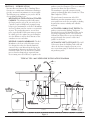
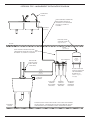
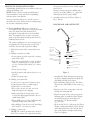
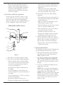
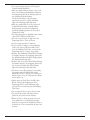
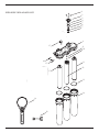
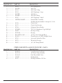
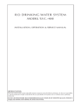
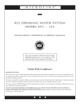
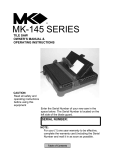
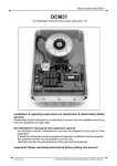
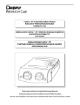
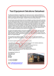
R. O. DRINKING WATER SYSTEM
MODEL T.F.C.-300
INSTALLATION, OPERATION & SERVICE MANUAL
IMPORTANT NOTICES:
This reverse osmosis system contains replaceable treatment components critical for effective performance. It is the user's responsibility to, and
the manufacturer strongly recommends that the user, periodically test the product water to verify the system is performing satisfactorily.
DO NOT USE WITH WATER THAT IS MICROBIOLOGICALLY UNSAFE OR OF UNKNOWN QUALITY, WITHOUT
ADEQUATE DISINFECTION BEFORE OR AFTER THE SYSTEM.
TABLE OF CONTENTS
SECTION I.
Page
INTRODUCTION ........................................................................................... 3
SECTION II.
SPECIFICATIONS .......................................................................................... 5
SECTION III.
INSTALLATION STEPS ................................................................................. 6
A. Faucet Installation ..................................................................................... 6
B. Feed Water Saddle Valve Installation ....................................................... 7
C. Drain Clamp Installation........................................................................... 7
D. R.O. Manifold Assembly Installation........................................................ 8
E. Position the Drinking Water Holding Tank
and Make the Final Hose Connections ..................................................... 9
F. Start Up ..................................................................................................... 9
SECTION IV.
OPERATION AND MAINTENTANCE ...................................................... 10
A. Normal Operation ................................................................................... 10
B. Changing Filters....................................................................................... 10
SECTION V.
TROUBLE SHOOTING GUIDE .................................................................. 12
EXPLODED VIEW AND PARTS LIST .............................................................................................. 14
SECTION I. INTRODUCTION
Your new Reverse Osmosis (R.O.) Drinking Water
System uses a combination of filtration technologies
to reduce unwanted contaminants in a water supply.
The following steps combine to give you the best in
clear sparkling drinking water:
product water (the Permeate). The excess minerals
are rinsed to drain (the Reject Water).
The membrane is specially constructed, fully
aromatic polyamide film and is classified as a Thin
Film Composite (T.F.C.).
The spiral wound construction of the R.O.
Membrane provides maximum surface area for
water production and is less susceptible to fouling
by particulate matter, turbidity and colloidal
materials.
MECHANICAL FILTRATION/ACTIVATED
CARBON–The sediment prefilter will remove
the larger particles such as silt, rust and scale. Its
5 micron (equal to 0.0002 inch) nominal rating
helps to give maximum life to the R.O. Membrane.
Activated carbon particles contain a vast network
of pores. The tremendous surface area of these
pores (typically 800–1200 square meters per gram
of carbon) gives the carbon very good adsorptive
sites for chlorine as well as other substances that
contribute to taste and odors.
REVERSE OSMOSIS MEMBRANE–The R.O.
Membrane is the heart of the filtration system.
It is designed to reduce the dissolved mineral
content of the water. Minerals picked up in the
environment by the water are measured as Total
Dissolved Solids (TDS). In the Reverse Osmosis
process, dissolved minerals are separated from
the incoming water (Feed Water) to produce the
ACTIVATED CARBON POST FILTER–The
product water from the Holding Tank passes
through the Activated Carbon Post Filter on the
way to the Dispensing Faucet. The Activated
Carbon Post Filter reduces tastes and odors that
may pass through the system. It adds a final
“polish” to the water.
AUTOMATIC SHUT–OFF VALVE–The ASO
Valve senses when the Holding Tank is full and
closes the feed water supply to prevent excess
reject water from going to drain when the unit is
not producing water.
1
DISPENSING
FAUCET
A
WITH
AIR GAP
TYPICAL T.F.C.–300 UNDER SINK INSTALLATION DIAGRAM
1
2
DISPENSING
FAUCET
A
WITH
AIR GAP
1
DRAIN
DISPEN
CLAM
P SING
FAUCET
A
WITH
AIR GAP
DRAIN
(3/8" Black)
PRODUCT
(3/8" Blue)
1
DRAIN
CLAMP
7
DRAIN
(3/8" Black)
E
DRAIN
(3/8" Black)
PRODUCT
(3/8" Blue)
DRAIN
(1/4" Black)
1
DISPENSING
FAUCET
A
WITH
AIR GAP
4
DISPENSING
FAUCET
A
WITH
AIR GAP 2
3
DRAIN
LAM
CCOVER
O P
2
FF VA
3
COVER
O
PRODUCT
(3/8" Blue)
RO MANIFOLD
3
COVER
O
2
4
DRAIN
ROCMANIF
LAMP OLD
34
RO COVER
MANIF
OLD
O
INLET
(1/4" RedD
) RAIN
(3/8" Black)
6 7
PRODUCT
(3/8" Blue)
5
DRINKING
T VA E
TER
SHUTOFF
HOLDING 2
T
TANK
DRAIN
CLAMP
4
LVE
3
6
DRINKING
T
TER
HOLDING
T
TANK
TANK
T
(3/8" Yellow)
E
65
INLET
(1/4" Red)
INLET
(1/4" Red)
ACTIVATED
A
4" MINI.NLET
CARBON
(1/4" Red)
T
TER
HOUSING
45
DRINKING
T
TER
LVE
HOLDING
T
TANK
Y
Y)
6
DRAIN
(1/4" Black)
DRAIN
(1/4" Black)
COVER
O
7
UTOFF VA
PRODSH
UCT
(3/8" Blue)
RO MANIFOLD
DRAIN
LOCATE
A DRAIN CLAMP
(1P/4" Black)
ABOVE "P" TRA
Y
Y)
DRINKING
T
TER
HOLDING
T
TANK
RO MANIFOLD
VE
LOCATE
A LDRAIN
CLAMP
Y
ABOVE "P" TRAP Y)
TANK
T
(3/8" Yellow)
5
LVE
REVERSE
OSMOSIS
HOUSING
SEDIMENT/
CARBON
PREFILTER
HOUSING
DRAIN
(1/4" Black)
LOCATE
A DRAIN CLAMP
ABOVE "P" TRAP
ACTIVATED
A
4" MIN. CARBON
T
TER
HOUSING
TANK
T
(3/8" Yellow)
LOCATE
A DRAIN CLAMP
ABOVE "P" TRAP
Y
Y)
Figure 1
3
TANK
T
(3/8" Yellow)
INLET
(1/4" Red)
REVERSE
SEDIMENT/
CTIVATED
A
OSMOSIS
CAARB
ON
4" MIN. CARBON
PREFILTER
T
TER
HOUSING
HHOUS
INGG
OUSIN
REVERSE
OSMOSIS
HOUSING
ACTIVATED
A
4" MIN. CARBON
T
TER
HOUSING
SEDIMENT/
CARBON
PREFILTER
HOUSING
REVERSE
OSMOSIS
HOUSING
SEDIMENT/
CARBON
PREFILTER
HOUSING
OPTIONAL T.F.C.–300 BASEMENT INSTALLATION DIAGRAM
�����������
������
��������������������������
����������������������
�����������������������
�������������������
��������
�������
�����������
�������������
�������������
���������������
�����
����
�������������
�������������������������������
���������������������������������
�����������������������������
�����������
�����������
�������������
������������
����������
��������������
�����������������
��������������
�������������
���������������������
���������
�����
����������
�����
������������
����������
��������
����������
�������
������������
�������
��������
�����
���������
������
��������
����
��������
��������
���������
�������
���������
�������
����������
�������
����������������������������������������������������������
��������������������������������������������������������
���������������������������������������������������
4
SECTION II. SPECIFICATIONS
TABLE A – QUALIFIED SYSTEM PERFORMANCE
Because the performance of an R.O. Membrane is highly dependent upon pressure, temperature, pH and TDS, the
following should be used for comparison purposes only.
Membrane Production
1
Membrane TDS Reduction
1
Drain (reject water) Flow
Empty Storage Tank Precharge
1
U.S.
Metric
40-60 gpd
151-227 lpd
93% minimum
93% minimum
3–5 x product flow
3–5 x product flow
5–7 psig air
35–48 kPa air
Industry standards measure R.O. Membranes performance with no backpressure on the product water, at 65 psig (448kPa) and 77°F (25°C). Further
conditions on the above are 600 ppm TDS. Production rate and TDS reduction figures are for a new Membrane that has been rinsed for 24 hours. The production
rate of a new Membrane can decrease by 10% per year or more, depending upon the scaling and fouling tendencies of the Feed Water.
TABLE B – RECOMMENDED OPERATING LIMITS FOR FEED WATER
Specifications
T.F.C. Membrane
Water Pressure
40–100 psig (280–690 kPa)
TDS
2000 ppm (also mg/l) max.
Temperature
pH
Hardness
40–100°F (4–38°C)
4–11 (optimum rejection at pH 7.0 - 7.5)
Less than 10 gpg (170 mg/l) or soften
Iron
Less than 0.1 ppm (also mg/l)
Manganese
Less than 0.05 ppm (also mg/l)
Hydrogen Sulfide
None
Chlorine
See note
Bacteria
Must be potable**
NOTE: Chlorine will damage a T.F.C. Membrane. The Sediment/Carbon Prefilter will remove chlorine from the incoming water. Change filter
every 6 months, more often if the water contains more than 1 ppm chlorine.
**DO NOT USE WITH WATER THAT IS MICROBIOLOGICALLY UNSAFE OR OF UNKNOWN QUALITY, WITHOUT ADEQUATE
DISINFECTION BEFORE OR AFTER THE SYSTEM.
5
SECTION III. INSTALLATION STEPS
All plumbing should be done in accordance with state
and local plumbing codes.
tile is penetrated, then use the carbide tipped
metal cutter.
Formica counter tops may be drilled with a
good 1¼" wood bit; drilling a 3/32" pilot hole
will help keep the bit going straight.
NOTE: Some codes may require installation by a
licensed plumber; check with the local plumbing
authority prior to installation.
3. Assemble and attach the Faucet (Refer to
Fig. 2, below.)
In restricted under–sink areas, it may be easier to
install the faucet first. Allow adequate tubing lengths
for any final component position.
LONG REACH AIR GAP FAUCET
A. Faucet Installation–The faucet contains an
anti–siphon air gap. While the system is producing
water, the drain water flows from the R.O.,
through the air gap and then to the household
drain. The purpose of the air gap is to prevent
water in the drain from backing up into the R.O.
Drinking Water System.
�����
The easiest installation is to use an existing spray
attachment hole. If the spray faucet hole is not
available, then the sink top must be drilled.
����������
��������������
1. Mark the location of the center of the faucet
base.
2a. Drilling a stainless steel sink:
•Center punch the hole to provide a starting
point for the drill.
�������������
�����������
�������
����������
������������
���������������
�������������
����������������
���������������
�����������
��������
•Start with a smaller drill as a pilot, and then
drill a ½" diameter hole to accept the bolt
of a 1¼" Greenlee Hole Punch (1¼" chassis
punch).
������������
�����������������
�����������������
�������������
•Clean away any chips.
Figure 2
•Install the punch and tighten the nut to cut
the hole.
•Assemble the Body and Spout by removing
the plastic shipping plug from the Body and
then firmly pressing in the Spout.
•Deburr any sharp edges.
2b. Drilling a porcelain sink:
It is best to use a special 1¼" diameter cutter
designed for porcelain. A carbide tipped
masonry bit is a second choice.
•In the following order, place the Face Plate
(Escutcheon) and Rubber Gasket on the 7/16"
stud.
•Place a piece of tape over the area to be
drilled to help prevent chipping.
•From the top of the counter place the stud
through the mounting hole.
•Drill a pilot hole for the porcelain cutter.
Use the pilot drill supplied with the kit or a
carbide tipped drill.
•From the bottom of the counter top, in the
following order, assemble the Split Washer,
the Drain Line Spacer (with open end
upwards), the 7/16" Washer and the
7/ " Hex Nut.
16
•When drilling the 1¼" hole, drill slowly and
carefully; the porcelain chips easily.
•To the end of the 7/16" stud put on the Plastic
Washer, Compression Fitting, Plastic Ferrule
and Compression Nut. Once snug by hand
take a pair of pliers and tighten the fitting.
Don’t over tighten.
•After drilling, clean the area well. Iron filings,
if left in place, can cause rust stains.
2c. Drilling a counter top:
NOTE: The counter top must be less than 1¼"
thick. Treat ceramic tile as porcelain until the
6
•Rotate the Spout and Body into position.
Align the Split Washer and the Spacer to
allow access to the Hose Barbs, and tighten
the Hex Nut while holding the faucet in
alignment with a padded Crescent wrench.
Do not over tighten.
fully clockwise (inward). A small amount of
water may escape from the outlet until it is
fully pierced.
When you feel the Valve Handle firmly
seated in the clockwise direction, the copper
tube is pierced and the valve is closed.
2b. To install on (hard) Steel or Brass Tubing
supply line.
B. Feed Water Saddle Valve Installation
Decide on location. Do NOT connect to a hot
water feed line. If you are not sure of the supply,
run the hot water and feel the supply piping.
Water over 100°F may cause permanent damage to
the R.O. Membrane. (Refer to Fig. 3 below.)
•The supply line should now be drained. Use a
battery powered or properly grounded drill to
avoid shock hazard.
•Drill a 3/16" hole in the supply line; (do not
drill through the opposite wall).
•Turn the handle to expose the lance no more
than 3/16" beyond the rubber gasket.
FEED WATER SADDLE VALVE
•Place the body of the valve over the hole so
that the lance fits into the hole.
Cold Water
Line
Saddle
•Assemble and tighten the brass screw.
Reversible
Back Plate
•Turn the Valve Handle clockwise (inward)
until firmly seated. The valve is closed.
3. With the Feed Water Saddle Valve closed,
open the sink faucet and the water supply and
allow the water to run for a few minutes to
flush any debris caused by the installation.
Valve
Handle
Tightening
Screw
•Close the faucet and check the Feed Water
Saddle Valve for leaks.
Insert
Plastic
Ferrule
C. Drain Clamp Installation
Compression
Nut
The following are instructions for discharging into
the sink drain pipe. (Refer to Fig. 1, page 3.)
Tubing To
Manifold
Inlet
1. Position the Drain Clamp on the sink drain
pipe above the drain trap. Allow room for
drilling. Tighten securely.
Figure 3
2. Use a battery powered or properly grounded
drill. Using the Clamp port as a drill guide,
drill a 7/32" hole through the wall of the drain
pipe. Do NOT penetrate the opposite side of
the pipe.
1. Shut off the water supply and drain the line.
2a. To install on (soft) Copper Tubing supply line:
•Turn the Handle of the Feed Water Saddle
Valve counter clockwise (outward) until the
lance does not protrude from the gasket. It
may have to be pushed in.
3. Locate the 3/8" Black Drain Tubing which is
shipped loose in the box.
•Assemble the Feed Water Saddle Valve on
the tubing.
NOTE: When cutting the polytubing make
clean, square cuts, failing to do so could result
in poor connections and possible leaks.
– for 3/8" OD tubing use the back plate side
with the small groove to prevent distortion of
the tubing.
NOTE: The lowest point of the line should be
the point of connection to the Drain Clamp.
There should be no sag in the line as this may
cause excessive noise as the reject water is
flowing to drain.
– for larger tubing (up to 5/8" OD) use the large
groove of the back plate.
•Assemble and tighten the brass screw.
•To pierce the tubing, turn the Valve Handle
7
3/8" DRAIN CLAMP ASSEMBLY
Drain Pipe
1/4" Nut
Drain Clamp
Front Plate
1/4" Screw
Drain Clamp
Back Plate
Black Drain Tubing
Figure 4
Firmly press one end of the tubing over the
drain outlet hose barb on the Air Gap
Faucet. Allow the tubing to relax, then press
firmly again to insure proper seating. No
connectors are required when attaching hose
to Hose Barbs. Route the tubing to the Drain
Clamp and trim to length.
The close proximity of a dishwasher or a trash
compactor may require special fabrication of a
mounting plate.
3/ "
8
1. The mounting bracket will accept either
#10 or #12 (5 mm) mounting screws spaced
on 6" (15 cm) centers. Allow at least 4" (10
cm) of clearance beneath the filter housings
to accommodate filter changes. Mark the
two locations (the bracket can be used as a
template). Install the screws and tighten them
until the heads are about 5/8" from the wall.
•Refer to Fig. 4, above. Insert the tubing into
the Drain Clamp. Make sure the tubing is
pressed all the way.
2. Locate the ¼" Red Feed Water Tubing.
Remove the red plug from the fitting labelled
“In” on the manifold and insert the tubing.
Reference the special supplement sheet in
the carton for proper connection of all tubing
and removal of plugs. Run the tubing along its
course to the Feed Water Saddle Valve, trim to
length. (Refer to Fig. 1, page 3.)
D. R.O. Manifold Assembly Installation
Various installation sites will require different
types of mounting fasteners; be sure the fastener
selected will provide a firm, solid mounting. A
support panel may be necessary on thin cabinet
walls or to span between wall studs on particle
board or drywall.
Do not drill through exterior cabinet walls or
leave sharp wood screw points exposed in readily
accessible cabinet interiors.
Refer to Fig. 3, page 7. To the end of the red
polytube install the Compression Nut, the
Plastic Ferrule, and the Insert. Connect to the
Feed Water Saddle Valve.
3. Locate the ¼" Black Drain Tubing. Remove
8
the black plug from the fitting labelled “Drain”
on the manifold and insert the tubing. The
end of the Black Drain Tubing that should be
inserted into the “Drain” port will have a green
drain restrictor in it. Run the tubing along its
course to the ¼" Hose Barb on the Dispensing
Faucet, trim to length and connect by firmly
pressing over the barb. Allow the tubing to
relax, then press firmly again to insure proper
seating.
1. Sanitizing the system. Use a drip pan to aid
clean–up.
NOTE: The system should be sanitized
BEFORE installing the Sediment/Carbon
Prefilter, the Activated Carbon Post Filter or
the R.O. Membrane.
•Use a good quality unscented 5¼% liquid
chlorine household bleach.
•Open the Dispensing Faucet by lifting the
black handle and open the Holding Tank
Shut–Off Valve (the handle should be
parallel with the valve body).
4. Locate the 8" Blue Product Water Tubing.
Remove the blue plug from the the elbow
connected to the fitting labelled “Out” on the
manifold and insert the tubing. Run the tubing
along its course to the Dispensing Faucet and
trim to length. See Fig. 2, page 6 for proper
installation.
3/
•Remove the plug on the underside of
the manifold labelled “SEDIMENT/
CARBON”. Pour one capful of bleach (this is
approximately 2 tsp. or 10 ml) into one of the
white Housings. Insert Housing O–ring into
the Housing groove, (press firmly in place).
Engage and firmly tighten the Housing hand
tight only.
5. Locate the 3/8" Yellow Tubing. Remove the
yellow plug from the fitting on top of the
manifold labelled “Tank” and insert the tubing.
(Refer to Fig. 1, page 3.)
•Remove the plugs labelled “MEMBRANE”
and “ACTIVATED CARBON” from the
underside of the manifold. To each of the
remaining white Housings, add one capful of
bleach. Insert a Housing O–ring, engage and
firmly tighten the Housings hand tight only.
6. Hang the Manifold Assembly on the
mounting screws and tighten. DO NOT
OVERTIGHTEN.
E. Position the Drinking Water Holding Tank and
Make the Final Hose Connections.
•Slowly open the Feed Water Saddle Valve
(turning counter clockwise).
1. Check the tank precharge pressure. Make sure
it is between 5 to 7 psig. If not, use a bicycle
hand pump or other pump to bring the pressure
up to the 5 to 7 psig range.
•As soon as the water begins to come out of
the Dispensing Faucet, close the Faucet.
2. Pull the cap/plug off the top of the tank where
the Tank Shut–Off should go. (Refer to Fig. 1,
page 3.)
•Let stand for 15 minutes.
3. Wrap Teflon tape around the ¼" male outlet
thread. Wrap in the direction of the threads
(clockwise, when looking down on the Holding
Tank). The tape will act as a thread sealant.
Screw on the Holding Tank Shut–Off Valve.
•At the end of 15 minutes, CLOSE the Feed
Water Saddle Valve and open the Dispensing
Faucet.
NOTE: During this time, check the system
carefully for leaks.
•Allow the Holding Tank to completely
drain, then remove the Sediment/Carbon
Filter Housing (the farthest of the three from
the In–Out ports), empty, and install the
Sediment/Carbon Prefilter. Firmly tighten the
Housing hand tight only.
4. Locate the 3/8" Yellow Tubing which is attached
to the elbow on top of the manifold and run
the tubing along its course to the tank and trim
to length. Insert the tubing into the Holding
Tank Shut–Off Valve fitting. Make sure the
tubing is pressed in all the way past the O–ring.
The fitting will grab the tubing and seal it in
place.
•Remove the Activated Carbon Filter Housing
(the closest of the three to the
In–Out Ports), empty, and install the
Activated Carbon Post Filter. Firmly tighten
the Housing hand tight only.
F. Start Up
At time of start up and each time the filters are
changed the system should be sanitized (also see
Operation and Maintenance Sec. IV, B.1–4, page
10).
2. Installing the R.O. Membrane:
•Remove the R.O. Membrane Housing, (the
middle one), and empty.
9
•Insert the Membrane up into the manifold.
(The O–rings should be up toward the
manifold.) Check the Housing O–ring for
proper position in its groove, engage and
firmly tighten the Housing hand tight only.
function. Other uses for the water are flowers,
pets and rinsing glassware.
With each use it is recommended that you
turn the tap for at least 10 seconds prior to
using water. This is especially important if the
water tap has not been used daily. After periods
of non–use, such as a week of vacation, it is
better to empty the holding tank and allow the
system to produce fresh water for use. If the
system is not used for 3–4 weeks or longer, it
is a good idea to resanitize the system and to
change the Sediment/Carbon Prefilter and the
Activated Carbon Post Filter.
3. Rinsing the system:
•Slowly open the Feed Water Saddle Valve
fully counter clockwise.
•The Holding Tank Valve should be open.
•Check the Air Gap Window on the
Dispensing Faucet to be sure that the drain
water is flowing. (Refer to Figure 2, page 6.)
The R.O. System is now making water.
B. Changing Filters
•Do not open the Faucet for at least 8 hours.
THIS R.O. SYSTEM CONTAINS FILTERS
WHICH MUST BE REPLACED AT REGULAR
INTERVALS TO MAINTAIN PROPER
PERFORMANCE. USE ONLY FACTORY
APPROVED FILTERS.
•Do not use the first three full tanks of water.
CAUTION: The R.O. Membrane is shipped
with a preservative in it. To ensure proper
rinsing of the R.O. Membrane it is important
to wait at least 8 hours before emptying each
tank.
All individuals should take adequate precautions
when changing the filters, including wearing
protective gloves, to avoid direct contact with the
exhausted filters.
When the Faucet is first opened, expect air
and carbon fines (very fine black powder)
from the Activated Carbon Post Filter to be
rinsed out. This is normal for the first tank
of water or after the Activated Carbon Post
Filter is changed.
The recommended interval for changing the
filters (not the R.O. Membrane) is every six (6)
months. Typical T.F.C. Membrane life expectancy
is three years. Local conditions may dictate more
frequent changes.
SECTION IV. OPERATION & MAINTENANCE
A. Normal Operation
NOTE: If the R.O. Membrane is to be replaced,
see Sec. III, F.1–3, page 9 for the proper procedure.
1. It is normal for the Total Dissolved Solids
(TDS) of the water to be higher than normal
during the first 5 gallons of operation; this is
due to the sanitizing solution and the new
Post Filter. After this water is rinsed to drain,
the removal rate should stabilize at a value of
greater than 75%.
Use a drip pan to catch any water that may spill
when the Filter Housings are removed. Refer to
Fig. 1, page 3 for component location.
1. Close the Feed Water Saddle Valve by turning
fully clockwise and open the Dispensing Faucet
by lifting the handle. Allow the Holding Tank
to empty.
2. R.O. systems produce drinking water at
relatively slow rates; it can take up to 5 hours
or more to fill the Holding Tank. Normal
operation is to let the Holding Tank fill with
water and then draw water as needed. When
the pressure in the Holding Tank falls to a
given pressure (as the water is being used) the
Automatic Shutoff Valve (ASO Valve) will
start water production and the system will refill
the Holding Tank. When the Holding Tank is
full and no water is being used, the ASO Valve
will automatically shut–off the feed water to
conserve water.
2. Loosen and remove the Sediment/Carbon
Filter and the Activated Carbon Filter
Housings. Discard the filters.
3. Wash the inside of the Housings using a mild
detergent and a soft cloth. Do not use abrasive
cleaners or pads. Thoroughly rinse all soap
from the Housings before reassembly.
4. To sanitize the system and replace the filters:
NOTE: The system should be sanitized before
installing the Sediment/Carbon Prefilter and
Activated Carbon Post Filter.
The more water that is used (up to the capacity
of the system) the better the R.O. system will
10
•Use a good quality unscented 5¼% liquid
chlorine household bleach.
•Add one capful of bleach (this is 2 tsp. or 10
ml) to the Sediment/Carbon Filter Housing
and temporarily install the Housing without
the Sediment/Carbon Prefilter.
Check the Housing O–ring for proper
position in its groove, engage and firmly
tighten the Housing hand tight only.
•Add one capful of bleach to the Activated
Carbon Filter Housing. Carefully fill the
Housing with tap water and temporarily
install the Housing without the Activated
Carbon Post Filter.
•The Dispensing Faucet should be open, slowly
open the Feed Water Saddle Valve.
•As soon as water begins to drip out of the
Dispensing Faucet, close the Faucet.
•Let the system stand for 15 minutes.
•At the end of 15 minutes, in the following
order, close the Feed Water Saddle Valve,
close the Holding Tank Valve and open the
Dispensing Faucet to release the pressure.
•Remove the Sediment/Carbon Filter Housing
and empty. Remove the wrapping and install
the Sediment/Carbon Prefilter. Firmly tighten
the Housing hand tight only.
•Remove the Activated Carbon Filter Housing
and empty. Remove the wrapping and install
the Activated Carbon Post Filter. Firmly
tighten the Housing hand tight only.
•Disconnect the yellow product water tubing
that runs from the Holding Tank to the
Manifold (see Fig. 1, page 3). Put 50 drops of
bleach (this is ½ tsp. or 3 ml) into the tubing
and reconnect it.
•Slowly open the Feed Water Saddle Valve.
When water begins dripping out of the
Dispensing Faucet, in the following order,
close the Faucet and then open the Holding
Tank Valve.
•Do not open the Faucet for at least 8 hours.
•Discard the first three full tanks of water
produced; they will contain chlorine.
•When the Faucet if first opened, expect air
and carbon fines (very fine black powder),
from the new Activated Carbon Post Filter to
be rinsed out. This is normal for the first tank
of water.
11
SECTION V. TROUBLE SHOOTING GUIDE
Problem
Possible Cause
Low quantity of Product Water
from Holding Tank
Feed Water Saddle Valve is plugged or Open Valve or unclog.
closed.
Clogged Sediment/Carbon Prefilter or Replace filters.
Activated Carbon Post Filter.
Feed Water pressure must be above
Low water pressure
40 psig.
R.O. Membrane is fouled.
See Feed Water operating limits.
Correct cause of fouling, replace
Membrane.
Air precharge pressure in Holding
Empty water from Holding Tank,
and with the faucet open, adjust air
Tank is too high.
pressure to 5–7 psig (35–48 kPa)
Air precharge is too low.
range.
Replace tank.
Air bladder in the Holding Tank is
ruptured.
Holding Tank Valve is closed.
Open Valve.
No drain flow, the Drain Restrictor is Clear or replace Drain Restrictor.
plugged.
No drain flow, the drain orifice in the Clear or replace the Air Gap Faucet.
Air Gap Faucet is plugged.
Free check.
The Check Valve is stuck.
The ASO Valve is malfunctioning.
Replace ASO Valve components.
Replace Post Filter.
Activated Carbon Post Filter
is plugged.
Air precharge in the Holding Tank is Empty water from Holding Tank and
with the faucet open, adjust the air
too low.
pressure to 5–7 psig (35–48 kPa)
range.
Check for leakage at the Air Valve
Stem.
Holding Tank Valve is partially closed. Open Valve.
Low pressure at the Dispensing
Faucet
The dispensing Faucet is out of
adjustment or faulty.
Heavy water use, Holding Tank is
depleted.
Low Water Production.
High Total Dissolved Solids (TDS) in Clogged Sediment/Carbon Prefilter.
the Product Water
Low Water Pressure.
R.O. Membrane O–ring is crimped.
R.O. Membrane brine seal is not
sealing up into the manifold head.
R.O. Membrane is expended.
12
Solution
Repair or replace Dispensing Faucet.
Allow Holding Tank to refill (adding a
second Holding Tank will increase
storage capacity).
See Low Quantity of Product Water
from Holding Tank section above.
Replace Filter.
Feed Water Pressure must be above
40 psig.
Check Feed Water Saddle Valve.
Check O–ring.
Check the brine seal.
If Membrane life is unusually short,
find and correct the problem.
Replace Membrane.
Problem
Possible Cause
Solution
High Total Dissolved Solids (TDS)
in the Product Water
(continued)
The Product Water and Drain Water
lines are reversed.
No drain flow, Drain Restrictor is
clogged.
No drain flow, the drain orifice in
the Air Gap Faucet is plugged.
The ASO Valve is not closing.
Correct plumbing.
Tastes and odors in the Product
Water
Drain Water overflows at the Air
Gap Faucet
Faucet leaks or drips
Fitting leaks in general
Clear or replace Drain Restrictor.
Clear or replace Air Gap Faucet.
Repair or replace the ASO Valve
Components.
New Activated Carbon Post Filter not Flush with several full tanks of
Product Water.
rinsed completely.
The Feed Water TDS has increased.
An increase in Feed Water TDS will
give a corresponding increase in
Product Water TDS.
Replace Filter.
The Activated Carbon Post Filter is
exhausted.
There is foreign matter in the Holding Clean, flush and sanitize the system.
Tank.
Replace the filters.
The Product Water and Drain Water Correct plumbing.
lines are reversed.
Dissolved gasses in the Feed Water.
Pretreat Feed Water to remove
dissolved gasses.
Increase in Product Water TDS.
See high TDS in the Product Water
section.
Air Gap is blocked.
Clear Air Gap.
Rinse with vinegar for removal of
calcium buildup.
Drain tubing is clogged.
Clear tubing.
Drain Clamp hole is misaligned.
Align with hole in the drain pipe.
Excessive drain flow rate.
Replace Drain Restrictor.
Leaks from spout.
Adjust Faucet by turning the tee bar
just below the handle to provide a
small amount of free play in handle
when shut off.
O–rings are bad, repair or replace
faucet.
Leaks from base of the delivery
O–ring is bad, replace O–ring.
tube.
Leaks from beneath the handle.
O–rings are bad. Repair or replace the
faucet.
Close the Feed Water Saddle Valve and relieve pressure before disconnecting
any tubing or replacing any fitting. Before replacing a fitting, re–cut the tubing
and re–insert into the fitting to see if that solves the leak. If pipe threads are
leaking, remove and retape with Teflon tape.
13
1
EXPLODED VIEW & PARTS LIST
2
3
4
5
6
7
8
15
16
9
10
11
15
12
����
��
����
17
13
14
18
19
MADE IN USA
14
DRAWING NO.
PART NO.
1......................
DESCRIPTION
2......................
3......................
4......................
5......................
6......................
7......................
8......................
S2009 .....................................
S2005PP.................................
S2013 .....................................
S2011 .....................................
S2007PP.................................
S2006PP.................................
S2010 .....................................
NSSTF0405M38PP ...............
9......................
10......................
11......................
12......................
13......................
14......................
15......................
16......................
17......................
18......................
19......................
S1276 .....................................
S1277 .....................................
S7028 .....................................
S1764RS ................................
S3069 .....................................
S7029–09 ...............................
PK–A6TEU4–MG.................
S2116–5 .................................
S7025 .....................................
S3072 .....................................
S1405 .....................................
DRAWING NO.
Self Tapping Screw
ASO Cap
ASO Cap O–Ring
ASO Diaphragm – Large
ASO Piston
ASO Piston Ring
ASO Diaphragm – Small
Manifold Plate Assembly
(Includes diagram numbers 1 through 10, 15, 16)
Check Valve
Check Valve Retainer
Sediment/Carbon Prefilter
T.F.C. R.O. Membrane 50 gpd (189 lpd)
Housing O–Ring
Housing
1/4" Post X 3/8" Polytube Elbow
Drain Restrictor 50 GPD (189 lpd) Green
Activated Carbon Post Filter
Wrench for Housing
1/4"–3/8" Fitting Wrench
OTHER COMPONENTS AS SHOWN IN FIGURE 1, PAGE 3.
PART NO.
DESCRIPTION
1......................
2......................
4......................
5......................
6......................
S1089–20 ...............................
S1117–01 ...............................
S1118–01 ...............................
C2000F ..................................
S1037 .....................................
Long Reach Air Gap Faucet
3/8" Drain Clamp Assembly
Feed Water Saddle Valve
Holding Tank
Holding Tank Shut–Off Valve
15
R.O. DRINKING WATER SYSTEM
FIVE/ONE YEAR LIMITED WARRANTY
What Does This Warranty Cover?
This warranty covers any defects in materials and workmanship of the R.O. Drinking Water System when
installed and operated within recommended parameters, with the exceptions stated below.
How Long Does The Coverage Last?
The manufacturer will warrant its R.O. Drinking Water System (except for the reverse osmosis membrane), for
a period of five years from the date of purchase. The reverse osmosis membrane is warranted for one year from
date of purchase. All implied warranties including merchantability and fitness for a particular purpose are limited
to five years from the date of purchase for the R.O. Drinking Water System, except for the reverse osmosis
membrane which is limited to one year from date of purchase. Some states do not allow limitations on how long
an implied warranty lasts, so the above limitations may not apply to you.
What Will The Manufacturer Do?
The manufacturer will repair or replace at its discretion any defective component. You must pay any labor
charges. You must also pay for shipping or travel charges to return the defective part(s).
What Does This Warranty Not Cover?
This warranty does not cover the disposable sediment and carbon filters whose service life depends on feed water
conditions. In addition, the membrane is only warranted if the required feed water conditions are met.
The above warranty will also not apply to any part of the R.O. Drinking Water System that is damaged because
of neglect, misuse, alterations, accident, misapplication, physical damage, or damage caused by fire, acts of
God, freezing or hot waters or similar causes. Consequential and incidental damages are not recoverable under
this warranty. Some states do not allow the exclusion or limitation of incidental or consequential damages, so the
above limitation or exclusion may not apply to you.
We recommend that you use only the manufacturer's replacement parts since improper parts or incorrectly
performed maintenance or repair voids this warranty.
How Do You Get Service?
In order to be eligible for service under this warranty you must (a) contact your local dealer who supplied the
unit.
How Does State Law Apply?
This warranty gives you specific legal rights and you may also have other rights which vary from state to state.
Your Water Treatment Professional:
Form No. S1462-03
04/05