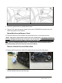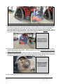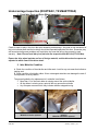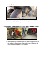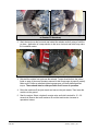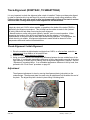
1
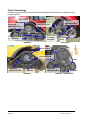
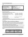
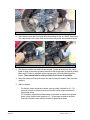
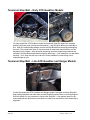
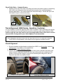
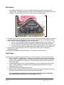
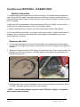
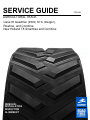
SERVICE GUIDE AGRICULTURAL TRACK Case IH Quadtrac (9300, STX, Steiger), Rowtrac, and Combine New Holland T8 Smarttrax and Combine REMOVAL INSTALLATION INSPECTION ALIGNMENT CPB-303 Table of Contents Introduction ........................................................................................................................................... 2 Track Terminology ........................................................................................................................... 3 General Tooling Requirements ......................................................................................................... 4 Special Torque Values ...................................................................................................................... 4 Time Estimates - Removal, Installation and Alignment ................................................................... 4 Track Removal (9300 Series, Quadtrac, Combine) .............................................................................. 6 Machine Preparation ......................................................................................................................... 6 Detension the track ........................................................................................................................... 6 Raise Machine and Remove Track ................................................................................................... 7 Remove Outside Front and Rear Idlers ............................................................................................. 7 Undercarriage Inspection (9300 Series, Quadtrac, Combine) .............................................................. 9 Installation of Replacement Track (9300 Series, Quadtrac, Combine) .............................................. 10 Tensioner Stop Bolt – Early STX Quadtrac Models .......................................................................... 12 Tensioner Stop Bolt – Late STX Quadtrac and Steiger Models ......................................................... 12 Track Alignment (9300 Series, Quadtrac, Combine) ......................................................................... 13 Check Alignment ............................................................................................................................ 13 Adjustment ...................................................................................................................................... 14 Final Check ..................................................................................................................................... 14 Track Removal (ROWTRAC, T8 SMARTTRAX) ............................................................................ 15 Machine Preparation ....................................................................................................................... 15 Detension the track ......................................................................................................................... 15 Raise Machine and Remove Track ................................................................................................. 16 Remove Outside Front and Rear Idlers ........................................................................................... 16 Undercarriage Inspection (ROWTRAC, T8 SMARTTRAX) ............................................................ 18 Installation of Replacement Track (ROWTRAC, T8 SMARTTRAX) .............................................. 19 Track Alignment (ROWTRAC, T8 SMARTTRAX) ......................................................................... 21 Check Alignment / Initial Alignment ............................................................................................. 21 Adjustment ...................................................................................................................................... 21 Final Check ..................................................................................................................................... 22 Summary ............................................................................................................................................. 22 Introduction This service guide is intended for distributors and dealers, and provides the basic information needed for track installation and service. Whenever tracks are changed, they also require alignment in order to maximize overall track life. Also, see the appropriate operator’s manuals for track maintenance, alignment procedures, and specific bolt torque by model. NOTE: Wheel bolt torque is critical. Too tight is as bad as too loose. Lubricate bolts with 10W-30 engine oil and use a torque wrench. Notice When servicing track machines, follow all manufacturers recommended safety precautions. Failure to follow safe procedures can result in injury or death. CBP-303 Camso | 8-2015 | 2 Track Terminology Familiarize yourself with the terms below before reading further instructions or working on any tracked machine. Drive Wheel Alignment Adjustment Bolt Alignment Adjustment Bolt Yoke Plate Bolts Tensioner Stop Bolt Midroller Idler Quadtrac 9300 Series Drive Wheel Yoke Plate Bolts Idler Alignment Adjustment Bolt Midroller Combine CBP-303 Idler Alignment Adjustment Bolt Midroller Rowtrac, T8 SmartTrax Camso | 8-2015 | 3 General Tooling Requirements Table 1 lists both the standard and specialized tools required for removal and installation of Camso tracks. Safety Glasses and Steel Toed Shoes CNH # 31-3183 Tension Cylinder Drain valve Pilot Pins (for idler installation) Ratcheting hoist / “Come Along” Selection of pry bars (1 at least 5 ft long) Infrared Thermometer* Torque Wrench (600 ft-lb / 813 Nm capacity) (4) 15 Ton / 15000Kg Minimum Support Stands 3/4” Air Impact Wrench (with 450 ft-lb / 610 Nm capacity) Several large wood blocks (2) Lifting Eyes Air / Hydraulic Jack (min 15 Ton / 15000Kg Capacity / 12” stroke) Soap solution (Track installation) 24mm and 30mm combination wrenches 30mm, 32mm, 34mm and 36mm ¾ drive sockets Table 1. Tooling List (* denotes special track tools) Special Torque Values QUADTRAC, ROWTRAC, T8 SMARTTRAX, COMBINE Tension cylinder stop bolt and nut (if required) ...………. 170 to 190 lb ft Steel idler wheel (early production – lubed **) ..………… 315 to 345 lb ft Cast idler wheel bolts ( late production - lubed ** ) ..…... 490 to 550 lb ft Yoke plate bolts ( lubed** ) ………………………………... 500 to 585 lb ft ( 235 to 260 Nm ) ( 427 to 468 Nm ) ( 575 to 630 Nm ) ( 678 to 793 Nm ) 9300 SERIES QUADTRAC Idler wheel bolts ( lubed** ) .……………………………. 315 to 345 lb ft ( 455 to 510 Nm ) Yoke plate mounting bolts ……………………………… 365 lb ft ( 500 Nm ) ** Lubed with 10W-30 engine oil ** NOTE: Wheel bolt torque is critical. Always use a torque wrench and refer to the operator’s manual for wheel bolt torques by specific model. Damage to tracks from failed hardware is not covered by track warranty! Time Estimates - Removal, Installation and Alignment The time required to change a track depends on the experience of the technician and the tools available. Table 2 lists average times for removal, installation, and alignment. This estimate is based on a service technician of average skills with the basic correct tools and working on firm, level ground. Working in adverse conditions can take significantly longer, while experienced technicians will be able to complete the work in a shorter time. * Note: If additional parts need to be replaced on the undercarriage as a result of a machine inspection, the total time may be significantly longer than shown. ** NOTE: With track removed always inspect front idler pivot bushings and mounting hardware for wear or play and repair as needed before installing new track. Excessive play in front idler pivot assembly will cause track alignment problems and track damage that will not be covered by track warranty. Track Removal, Inspection & Installation Track Alignment Single Track (man hrs) Single Track (man hrs) 1.5 - 2 0 - 1* Table 2. Estimated man hours required for average track installation and alignment CBP-303 Camso | 8-2015 | 4 Updates to consider before installing new tracks: Note: Remember, installing a new track on a worn undercarriage will result in significantly reduced track life, the same as a new tire on a vehicle with worn steering components. Track wear and damage is not covered by warranty. Check the old tracks prior to removal for wear characteristics that may indicate what UC components need repair. Check idler and midroller flanges for damage, proper thickness, and cracks – all of which will reduce drive lug and track life. Check the idler pivot bushings for wear. If loose, the track will not stay aligned. Early drive lug damage will result. Bushing Drive Wheel Scrapers – Make sure the machine is equipped with drive wheel scrapers, and adjusted correctly to 3mm clearance without contacting the wheel. Adjusted correctly, the scrapers remove debris build-up on the smooth surface of the drive wheel. Debris build-up reduces drive lug and inner track life. Drive wheel scrapers should be used on all drive wheels and in all applications. Configurations are different based on models and age of machine. Consult with the CNH dealer for part numbers and quantities for specific machines. Scraper CBP-303 Camso | 8-2015 | 5 Track Removal (9300 Series, Quadtrac, Combine) Machine Preparation 1. If possible, always move the machine to a flat, firm surface. The machine can be raised much easier and will be more stable if the track removal and installation is completed on a stable surface. A hard surface also makes it easier to slide the track out from under the machine, and allows use of a forklift if available. 2. Make sure that any implements are disconnected from the hitch or drawbar on tractors, and headers are not attached on combines. Never work on a machine with an implement attached or header in the air, as this is an unstable condition. 3. Clean the machine before working on it. Dirt and debris makes access to bolts difficult. 4. Once the machine is positioned – turn engine off and remove the key, install articulation lock (if equipped). Do not start the machine while track undercarriage is disassembled, or injury and machine damage could result. Important 9300 Series/Quadtrac/Combine - After detensioning tracks make sure the tensioner Stop Bolt is installed. This will prevent the idler pivot assembly from moving forward after the track is removed. See “Track Terminology” pictures on page (3) of this document for Stop Bolt location. Detension the track 1. Obtain the CNH part number 31-3183 Tension Cylinder Drain Valve. This is usually stored in the cab and comes with new machines. This drain valve/hose will safely remove pressure in the track tensioning system. Drain Port Location 2. Locate the drain port on the undercarriage. Remove the dust cap. Make sure the drain valve is CLOSED. Then attach the drain valve hose to the coupler on the undercarriage. CBP-303 Camso | 8-2015 | 6 ** NOTE – Track tension cylinder pressure can be 3000 psi or higher. Use caution. Valve must be opened slowly. Drain Port Location 3. Insert the opposite end into a suitable drain bucket. 4. Using a 15/16” open end wrench, slowly turn the valve CLOCKWISE to open the valve and relieve the pressure in the tensioner. Leave the tension cylinder drain valve connected, as you will need to further retract the front tensioner later on. Raise Machine and Remove Track 5. Raise the machine until the midrollers are approximately one (1) inch above the track. **NOTE – lifting devices with focalized contact areas such as bottle jacks, can damage or fail the axle housings. We highly recommend you do not jack on the axle housing. Also do not attempt to lift or support the machine by jacking or lifting on the front cast weights or the front cast weight mounting area (if equipped). The front cast weight mounting area is not strong enough to support the weight of the machine. Please refer to the operator’s manual or contact the Case IH dealer for recommended lifting instructions called out in the Service Manual. Remove Outside Front and Rear Idlers 6. Remove both front and rear idler bolts and spacers (not all have spacers), and remove both idler wheels. CBP-303 Camso | 8-2015 | 7 7. With both idler wheels removed, raise the machine approximately eight inches off the ground, or until the midrollers clear the track drive lugs. Using a boom truck to work track off the drive wheel and rear idler simultaneously 8. The best way to remove the tracks is to work the track off the inner idler wheels while at the same time working the drive lugs out of the drive wheel pockets. Slowly slide the track out from under the midrollers, and move to a suitable location. Using a boom truck to remove track 9. Please note: removal of the track will require the use of either a forklift or a boom truck, as the tracks weigh approximately 1100 lbs. Use caution when removing tracks, or injury could result. 10. If the tension cylinder is still partially extended, it will greatly help in track installation later if you use either a come-along or some other means to retract the tension cylinder as far as possible. One method is shown below to accomplish this. Other methods can be used. Chain attached to rear swing link bolt Gently pull up on the chain to cause to force linkage inwards cylinder to retract 11. With the tensioner fully retracted, close drain valve and remove the oil drain hose. CBP-303 Camso | 8-2015 | 8 Undercarriage Inspection (9300 Series, Quadtrac, Combine) 1. Front Idler Pivot and Drive wheel Inspection Inspection of front idler pivot assembly and drive wheel Check the wear or play in the front idler pivot assembly and bearings - Any side to side movement of this joint indicates wear, and bushings should be replaced at this time. Excessive play in idler pivot assembly will cause track alignment problems and rapid drive / guide lug wear that will not be covered by track warranty! 2. Idler Midroller Condition A. Check the condition of the midroller and idler seals. Look for any wet areas that indicate a leaking seal. B. Check condition of midroller rubber. Worn or damaged midrollers can damage the track if not replaced in a timely fashion. The general guideline for replacement of a midroller is as follows: More than 1/3 of the total rubber is missing around the entire midroller All the rubber is missing at any point all the way across the midroller Any flat spots are seen which may indicate midroller stopped turning More than 1/3 of total rubber is missing Midroller must be replaced. CBP-303 More than 1/3 of the total rubber is missing Midroller should be replaced Camso | 8-2015 | 9 3. Idler Condition Idler Inspection Also check idlers for missing rubber or for cracks at the bolt holes. Use similar criteria in order to determine if idlers should be replaced due to loss of rubber. Installation of Replacement Track (9300 Series, Quadtrac, Combine) Installation of track is basically the reverse order of the removal. Track Installation 1. Using hoist or other means, carefully slide track under the midrollers while also lifting it over and into the drive wheel, but not yet engaging the teeth. You may have to use a pry bar to adjust the track so that the track drive lugs fall into the drive wheel pockets. CBP-303 Camso | 8-2015 | 10 Track installation 2. Work the track over the front inside idler wheel using a hoist or a forklift. Application of a soap solution to the inner front and rear idler may make the installation easier. Track installation 3. Reinstall the outside front and rear idler wheels. Torque wheel bolts to the values listed on page 4 (also see Operators manual for bolt torque spec by specific model). Make sure to follow an alternate tightening sequence until bolts holds specified torque. These should also be retorqued after first 3 hours of operation. 4. Raise the machine off the jack stands and remove the jack stands. Then lower the machine. 5. Start the engine. - - CBP-303 For tractors, select a hydraulic remote valve and hold it stroked for 15 – 30 seconds to observe the track tensioner fill and the track tension increase to operational values. For combines, press and hold the header reel fore/aft or header reel up/down button on the multifunction handle for 15 – 30 seconds to observe the track tensioner fill and the track tension increase to operational values. Camso | 8-2015 | 11 Tensioner Stop Bolt – Early STX Quadtrac Models On early production STX Quadtrac models the tensioner Stop Bolt upper hole (storage position) and lower hole (normal stop bolt position – see RH photo above) are vertically in line. With this undercarriage design, remove the Stop Bolt before tensioning and aligning the track. This needs to be done on certain models to make sure that full tension can be developed on the tracks. After the below tensioning and track alignment procedures are complete, the Stop Bolt should slide through the hole freely. If so, install bolt, nut and fasten securely. If not, keep the bolt in the cab so it will be available to install during future undercarriage service. Tensioner Stop Bolt – Late STX Quadtrac and Steiger Models On the later production STX Quadtrac and Steiger models, the upper tensioner Stop Bolt hole (storage position) and lower hole (normal Stop Bolt position) are not vertically aligned. With this design it is not necessary to remove the Stop Bolt. It can always remain in the lower positions (see photo above) and does not need to be removed for track tensioning or alignment. CBP-303 Camso | 8-2015 | 12 Check Relief Valve – Updated Version Updating to the new check relief valve design will assure the tension system is maintaining track tension and help protect the track and tension system from overload damage in extreme applications. The notches identify the new valve design. Consult with your local CNH dealer for part numbers and pricing. Old New New Track Alignment (9300 Series, Quadtrac, Combine) It is very important to check the alignment after a track is installed. Tracks must always be aligned in order to maximize drive lug and wheel life, as well as reducing overall rolling resistance. Note: Failure to align the track may result in drive lug damage and/or failure of the track in a short amount of time. Damage due to poor initial alignment is not warrantable. Note: Track misalignment will reduce the life of the drive lugs on the track. It is very important to align the tracks when new and periodically recheck them for proper alignment to maximize track life. Check Alignment 1. Drive the machine straight ahead at not faster than 5 MPH, on a flat surface, and with no steering input, for a distance of at least 400 feet. 2. Coast to a stop without steering or braking. 3. Observe the gap between the drive lugs and the rolling stock (midrollers and idlers) (see below). A track in alignment should have drive lugs running down the centerline on flat ground. If drive lugs are running to one side and contacting the rolling stock, then an alignment adjustment is probably needed. Example of misaligned track CBP-303 Misaligned Track Drive lugs rubbing on wheels Camso | 8-2015 | 13 Adjustment Adjustment Bolt The alignment adjustment is done by moving the alignment plate (yoke plate) on the undercarriage. The alignment plate is moved using an adjustment bolt located at the end of the plate. The alignment plate is locked in place using 6 retaining bolts. 1. Loosen the 3 front and 3 rear alignment plate bolts just enough to allow the washer to spin free. 2. Turn the adjustment bolt (located near arrow) at least 1 full turn to move the alignment plate either forward or rearward depending on the change needed: a. To move the track INWARD adjust the alignment plate rearward on the machine. This will move the plate back and should widen the exposed slot behind the bolt heads. b. To move the track OUTWARD adjust the alignment plate forward on the machine. This will move the plate ahead and should widen the exposed bolt slot in front of the bolts. 3. Retighten the 6 alignment plate bolts to 365 ft-lbs (9300 series), and 500 -585 ft-lbs (Quadtrac/Combine). 4. Recheck track alignment and repeat steps 1-3 as needed to center the track. Final Check Once the drive lug alignment appears centered, a final active alignment check should be done. 1. Drive the tractor in a straight line at moderate speed without steering input approximately 400 m (1300 ft ) or approximately ¼ mile. Stroke a remote function (tractors) or hold the header reel fore/aft button (combines) for 15 seconds while driving to ensure tracks are tensioned properly. 2. Observe the drive lugs to see if they are centered on the drive wheel and front and rear idlers. If slight adjustment is needed, loosen the alignment plate bolts and move the adjustment bolt 1-2 turns. 3. Tighten and torque the alignment plate bolts. 4. Repeat step 1 and adjust the alignment plate position if needed until temperatures of the drive lug outside faces are similar on both sides of the drive lugs. It is recommended alignment be rechecked again after 10-20 hours of operation. Some track alignment changes can be expected over time. CBP-303 Camso | 8-2015 | 14 Track Removal (ROWTRAC, T8 SMARTTRAX) Machine Preparation 1. If possible, always move the machine to a flat, firm surface. The machine can be raised much easier and will be more stable if the track removal and installation is done on a stable surface. A hard surface also makes it easier to slide the track out from under the machine, and allows use of a forklift if available. 2. Make sure that any implements are disconnected from the hitch or drawbar. Never work on a machine with an implement attached, as this is an unstable condition. 3. Clean the machine before working on it. Dirt and debris makes access to bolts difficult. 4. Once the machine is positioned – turn engine off and remove the key, install articulation lock (if equipped). Do not start the machine while track undercarriage is disassembled or injury and machine damage could result. Detension the track 5. To aid in track detensioning, drive the front idler wheels up on wood blocks as shown below. This will allow the weight of the machine to help retract the front idler wheels once the tension is released. 6. Obtain the CNH part number 31-3183 Tension Cylinder Drain Valve. This is usually stored in the cab and comes with new machines. This drain valve/hose will safely remove pressure in the track tensioning system. Drain Port Location 7. Locate the drain port on the undercarriage. Remove the dust cap. Make sure the drain valve is CLOSED. Then attach the drain valve hose to the coupling. ** NOTE – Track tension cylinder pressure can be 3000 psi or higher. Use caution. Valve must be opened slowly. CBP-303 Camso | 8-2015 | 15 Drain Port Location 8. Insert the opposite end into a suitable drain bucket. 9. Using a 15/16” open end wrench, slowly turn the valve CLOCKWISE to open the valve and relieve the pressure in the tensioner. Raise Machine and Remove Track 10. Raise the machine until the midrollers are approximately one (1) inch above the track. **NOTE – lifting devices with focalized contact areas such as bottle jacks, can damage or fail the axle housings. We highly recommend you do not jack on the axle housing. Also do not attempt to lift or support the machine by jacking or lifting on the front cast weights, or the front cast weight mounting area. The front cast weight mounting area is not strong enough to support the weight of the tractor. Please refer to the machine operator’s manual, or contact the Case IH or New Holland dealer for recommended lifting instructions called out in the Service Manual. Remove Outside Front and Rear Idlers 11. Remove both front and rear outside idler wheel bolts and remove both idler wheels. 12. With both idler wheels removed, raise the machine approximately eight inches off the ground or until the midrollers clear the track drive lugs. CBP-303 Camso | 8-2015 | 16 Using a forklift to lift track off the drive wheel 13. The bottom of the narrow tracks (16” and 18” widths) can typically be slid outwards and off of the inside idlers by hand. The wider tracks (24” and 30” widths) can be slid outwards by hand, or by using a strap and forklift to pull the bottom of the track out from under the midrollers. Once the bottom of the track is slid out, the track will lift out of the drive wheel pockets. Use a boom truck with a strap, a forklift with a strap, or the tines of a forklift to carefully lift the track off of the drive wheel and then outwards away from the machine. Using a forklift to safely move track to a suitable location 14. Please note: removal of the track will require the use of either a forklift or a boom truck, as the tracks weigh approximately 540lbs – 950lbs (depending on width). Use caution when removing tracks, or injury could result. 15. If the tension cylinder is still partially extended, it will greatly help in track installation later if you use either a come-along or some other means to retract the tension cylinder as far as possible. One method is shown below to accomplish this. Other methods can be used. Pulling up on chain to retract tension cylinder to aid in track installation 16. With the tensioner fully retracted, close drain valve and remove the drain valve tool. CBP-303 Camso | 8-2015 | 17 Undercarriage Inspection (ROWTRAC, T8 SMARTTRAX) 1. Front Idler Pivot and Drive Wheel Inspection Inspection of front idler pivot assembly and drive wheel Check for wear or play in the front idler pivot assembly and bearings - Any side to side movement of this joint indicates wear and the bushings should be inspected/replaced at this time. Excessive play will cause track alignment problems and rapid drive lug wear that will not be covered by track warranty. Note: Ensure front idler pivot pin bolts are torqued to 424-465 ft-lb (575-630 Nm). Ensure the drive wheel pockets are free of foreign material, and the drive wheel scrapers are adjusted to within 3mm of the drive wheel. 2. Idler Midroller Condition A. Check the condition of the midroller and idler seals. Look for any wet areas that indicate a leaking seal. B. Check condition of midroller rubber. Worn or damaged midrollers can damage the track if not replaced in a timely fashion. The general guideline for replacement of a midroller is as follows: More than 1/3 of the total rubber is missing around the entire midroller All the rubber is missing at any point all the way across the midroller Any flat spots are seen which may indicate midroller stopped turning More than 1/3 of total rubber is missing Midroller must be replaced. CBP-303 More than 1/3 of the total rubber is missing Midroller should be replaced Camso | 8-2015 | 18 3. Idler Condition Idler Inspection (Quadtrac shown above, however the same procedure applies to Rowtrac/T8 Smarttrax) Also check idlers for missing rubber or for cracks at the bolt holes. Use similar criteria in order to determine if idlers should be replaced due to loss of rubber. Installation of Replacement Track (ROWTRAC, T8 SMARTTRAX) Installation of track is basically the reverse order of the removal. Track Installation 1. Using boom truck, forklift with a strap, or CAREFULLY using the tines of a forklift, set the track on top of the drive wheel and then adjust the track so the drive lugs fall into the drive wheel pockets. Place a block of wood between the track and forklift tines, and then push the bottom of the track under the midrollers. Using pry bars to help work the track under the midrollers is acceptable if no forklift is available. CBP-303 Camso | 8-2015 | 19 Track installation (Quadtrac shown above, however the same procedure applies to Rowtrac/T8 Smarttrax) 2. Work the track over the front and rear inside idler wheels carefully using a forklift or pry bars. Application of a soap solution to the inner front and rear idlers may make the installation easier. Idler Wheel installation 3. Reinstall the outside front and rear idler wheels. Torque wheel bolts to the values listed on page 4 (also see Operators manual for bolt torque spec by specific model). Make sure to follow an alternate tightening sequence until bolts holds specified torque. These should also be retorqued after first 3 hours of operation. 4. Raise the machine off the jack stands and remove the jack stands. Then lower the machine to the ground. 5. Start the engine. Select a hydraulic remote valve and hold it stroked for 15 – 30 seconds to observe the track tensioner fill and the track tension increase to operational values. CBP-303 Camso | 8-2015 | 20 Track Alignment (ROWTRAC, T8 SMARTTRAX) It is very important to check the alignment after a track is installed. Tracks must always be aligned in order to maximize drive lug and wheel life, as well as reducing overall rolling resistance. Note: Failure to align the track may result in drive lug damage and/or failure of the track in a short amount of time. Damage due to poor initial alignment is not warrantable. Notes: -Apply dry dusty soil, Oil-Dri, talcum powder, or graphite to the inside of the tracks PRIOR to performing the alignment procedure. This will help coat the rubber to make it slick (instead of sticky) which can help when fine tuning the track alignment. - Narrow tracks on narrow rolling stock typically “wander” more in normal operation. When inspecting the location of the drive lugs compared to the idler wheels, it is not always representative of where the track is most often located during operation. For that reason, the visual check is not reliable. All alignment adjustments made should be based off of the temperature differential method described below. Check Alignment / Initial Alignment 1. Drive the machine straight ahead at not faster than 5 MPH, on a flat surface, and with no steering input, for a distance of at least 400 feet. 2. Coast to a stop without steering or braking. 3. Using your hand, observe the temperature difference between the two outside faces of the drive lugs. If a noticeable temperature difference is felt by hand and/or one side of the drive lugs are shiny or shows signs of rubbing, then an alignment adjustment is needed. See the “Adjustment” procedure below. If no noticeable temperature difference is felt by hand, then proceed to the “Final Check” procedure on page 22. Adjustment Adjustment Bolt The alignment adjustment is done by moving the alignment plate (yoke plate) on the undercarriage. The alignment plate is moved using an adjustment bolt located at the end of the plate. The alignment plate is locked in place using 6 retaining bolts. Lock Bolts CBP-303 Camso | 8-2015 | 21 5. Loosen the 3 front and 3 rear alignment plate bolts just enough to allow the washer to spin free. 6. Turn the adjustment bolt (located near arrow) at least 1 full turn to move the alignment plate either forward or rearward depending on the change needed: a. To move the track INWARD adjust the alignment plate rearward on the machine. This will move the plate back and should widen the exposed slot behind the bolt heads. b. To move the track OUTWARD adjust the alignment plate forward on the machine. This will move the plate ahead and should widen the exposed bolt slot in front of the bolts. 7. Retighten the 6 alignment plate bolts to 500 -585 ft-lbs. 8. Recheck track alignment and repeat steps 1-3 as needed to obtain minimal temperature difference and no rubbing of the drive lugs. Final Check Once the initial alignment is completed resulting in minimal temperature differential or drive lug rubbing, a final alignment check should be done. 9. Drive the tractor in a straight line at moderate speed (10mph – 15mph) without steering input approximately 400 m (1300 ft ) or approximately ¼ mile. Stroke a remote function for 15 seconds while driving to ensure tracks are tensioned properly. 10. Using your hand or an infrared temperature gun, verify the outside faces of the drive lugs are similar in temperature, indicating a properly aligned track. If one side of the drive lugs is significantly warmer than the opposite sides (20 degrees F or more differential), make small adjustments to “fine tune” the track alignment. Loosen the alignment plate bolts and move the adjustment bolt ½ turn in the proper direction. 11. Tighten and torque the alignment plate bolts to 500 -585 ft-lbs. 12. Repeat step 9 and adjust the alignment plate position if needed until temperatures of the drive lug outside faces are similar (within 20 degrees F) on both sides. It is recommended alignment be rechecked again after 10-20 hours of operation. Some track alignment changes can be expected over time. Summary After alignment and installation is completed, provide the customer the following documents: Warranty Certificate (appropriate for application – Ag or Scraper) Track Operational Guidelines Brochure Product Registration Card Take a few minutes to review the information in the brochure, and to discuss the warranty coverage details. Also make sure to record track part number, serial numbers and installation date on the warranty certificate for future reference. For additional information on the maintenance of the undercarriage, and on the extended procedures for servicing and rebuilding these areas, refer to the proper service or owner’s manual (available from the local Case IH or New Holland dealer). Email any suggestions for improvements, clarifications, or errors, to [email protected]. CBP-303 Camso | 8-2015 | 22 camso.co