1
PS Series
PS10 - PS10TD - LS500
PS15 - PS15TD - LS1000
User Manual
User Manual
Release : 1.31
Date : 29/09/2005
PS10
PS10TD
LS500
PS15
PS15TD
LS1000
INTRODUCTION
p.2
___________________________________________________________________________________________________
I. INTRODUCTION
4
II. LOUDSPEAKERS
4
II.1. GENERAL SETUP INSTRUCTIONS
II.1.a. TDcontroller use
II.1.b. Speaker Wiring
II.1.c. Initial Setup Precautions
II.2. ASYMMETRICAL HORN CONFIGURATION
II.2.a. Principle
II.2.b. « Front of house » Configuration
II.2.c. « Stage Monitor » Configuration
II.3. SUBBASS USE (OPTIONAL)
II.3.a. General Recommendations
II.4. ACCESSORIES
II.4.a. Stand, Mast & U Coupler
II.4.b. Flying rails Accessories & Rings
II.4.c. Omnimount® style clamps
II.5. USE & MAINTENANCE
II.5.a. Checking the PS10 & PS15 internal fuses
II.5.b. Troubleshooting
II.5.c. Maintenance & Warranty
III. AMPLIFIERS
9
III.1. RECOMMENDED POWER
III.2. CURRENT CAPABILITY
III.3. GAIN
9
9
9
IV. TDCONTROLLER USER GUIDE
10
IV.1. READ BEFORE USE
IV.2. FRONT PANEL
IV.2.a. Turning the LSub channel on (On)
IV.2.b. Adjusting the LSub level (Sub Level)
IV.2.c. Amplifier control on LSub channel (Sense & Pk)
IV.2.d. LSub protection indicator (VLF)
IV.2.e. Amplifier control on PS channels(Sense & Pk)
IV.2.f. PS protection indicators (LF & HF)
IV.2.g. Enhanced protection trimmer (Protect)
IV.3. REAR PANEL
IV.3.a. Audio Inputs
IV.3.b. Audio Outputs
IV.3.c. Output Level Switch
IV.3.d. Sense inputs
IV.3.e. Earth Lift
IV.4. SETTING-UP ADVICE
IV.4.a. Recommendations for wiring the Sense lines
IV.4.b. Connecting the audio outputs
User Manual
Release : 1.31
Date : 29/09/2005
4
4
4
5
5
5
6
6
6
6
7
7
7
8
8
8
8
9
PS10
PS10TD
LS500
PS15
PS15TD
LS1000
10
10
11
11
11
11
11
11
11
12
12
12
13
13
14
15
15
15
INTRODUCTION
p.3
___________________________________________________________________________________________________
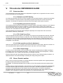
V. TDCONTROLLER REFERENCE GUIDE
16
V.1. LINEAR SECTION
V.1.a. Subsonic and VHF filtering
V.1.b. Equalizing acoustical response
V.1.c. PS / LSub Cross-Over
V.1.d. LSub operation and level adjustment
V.1.e. Gain. Output stage
V.2. SERVO CONTROL SECTION
V.2.a. VCAs and VCEQs
V.2.b. Displacement control
V.2.c. Temperature control
V.2.d. Dynamic control
V.2.e. Peak Limiter
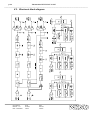
V.3. ELECTRONIC BLOCK DIAGRAM
16
16
16
16
16
16
16
17
17
17
17
17
18
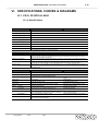
VI. SPECIFICATIONS, CURVES & DIAGRAMS
19
VI.1. PS10, PS10TD & LS500
VI.1.a. Specifications
VI.1.b. Dimensions
VI.1.c. Curves
VI.1.d. Connection Diagrams
VI.2. PS15, PS15TD & LS1000
VI.2.a. Specifications
VI.2.b. Dimensions
VI.2.c. Curves
VI.2.d. Connection Diagrams
19
19
20
21
22
23
23
24
25
26
VII. INDEX
User Manual
Release : 1.31
Date : 29/09/2005
27
PS10
PS10TD
LS500
PS15
PS15TD
LS1000
INTRODUCTION
p.4
___________________________________________________________________________________________________
I.
INTRODUCTION
Thank you for selecting NEXO PS Series equipment. This manual intends to provide you with necessary
and useful information about your PS speaker system :
PS10 & optional LS500 subbass
PS15 & optional LS1000 subbass
The PS15 can be used either in passive mode or bi-amped (two-way active). Most of the information
within this manual refers to the PS15 used in passive mode. At the date of writing this manual, the
specific processor required to use the PS15 in active mode was not yet available.
Please devote some attention to reading this manual. A better understanding of some specific
features of the PS series (like the asymmetrical directivity horn configuration) will help you to
operate your system to its full potential.
II.
LOUDSPEAKERS
II.1. General Setup Instructions
II.1.a. TDcontroller use
Performance, sound quality and reliability of these speaker systems are entirely dependent on proper
setup and use of the appropriate TDcontroller :
PS10 TDcontroller for PS10 systems (with or without LS500).
PS15 TDcontroller for PS15 systems (with or without LS1000).
These two controllers are not interchangeable. Each one is precisely matched to the corresponding
cabinets.
We strongly recommend to all new users the careful reading of the manual with regard to specific setup
and use of the TDcontroller.
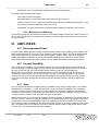
II.1.b. Speaker Wiring
The louspeakers are connected with SpeakonNL4FC plugs (not supplied). A wiring diagram is printed on
the connection panel located on the back of the cabinets.
The 4 pins of the 2 Speakon plugs identified in / out are paralleled within the enclosure. Each of these
connectors can thus be used indifferently and simultaneously receive the power amplifier signals feeding
the main PS cabinets and the optional LSub (if present) : a single 4 conductor cable can connect the
amplifier rack to 1 or 2 PS plus 1 LSub.
On the PS10, LS500, LS1000 and PS15 (used in passive mode), the connectors wiring is as follows :
Speakon Connector
pin 1+
pin 1pin 2+
pin 2-
User Manual
Release : 1.31
Date : 29/09/2005
PS10
PS10TD
LS500
Ö
Ö
Ö
Ö
PS15
PS15TD
LS1000
Signal
Subbass + (optional)
Subbass - (optional)
Main PS system +
Main PS system -
LOUDSPEAKERS
p.5
___________________________________________________________________________________________________
An additional Speakon connector on the PS15 connection panel is identified as 2 WAY ACTIVE; it is
reserved for operation in active mode (biamp) and wired as follows :
Speakon Connector
pin 1+
pin 1pin 2+
pin 2-
Ö
Ö
Ö
Ö
Signal
PS15 Bass +
PS15 Bass PS15 HF +
PS15 HF -
Cable choice consists mainly of selecting the correct cable section (size) in relation to the load
impedance and the cable length. Too small a cable section would increase its serial resistance, this
would induce power-loss and response variations (damping factor).
The following table indicates, for 3 common sizes, a cable length with a maximum serial resistance equal
to 4% of the load impedance (damping factor = 25).
Cable Section
1,5 mm² [AWG # 14]
2,5 mm² [AWG #12]
4 mm² [AWG #10]
Maximum Length
Impedance = 8 Ohms Impedance = 4 Ohms
12 m [40 ft]
6 m [20 ft]
20 m [64 ft]
10 m [32 ft]
32 m [104 ft]
16 m [52 ft]
II.1.c. Initial Setup Precautions
When starting up a system including brand new cabinets, NEXO recommends gradual power ramp up.
The loudspeaker components may need stabilizing during the very first hours of usage. This is
particularly true for adhesives within the speakers' moving assemblies.
In all cases it is advisable to connect the loudspeakers only after all the other components have been
wired and are operating correctly. This is particularly important for the amplifiers and the TDcontroller. It is
good practice to turn down all the amplifiers' gains before connecting the cabinets and to turn them on
again individually with a medium level music source fed into the system. The Sense LEDs of the
corresponding TDcontroller channel should light up accordingly. This will help to locate cabling errors,
particularly Left to Right or LF to HF Sense line inversions which would disable the TDcontroller
protections and may invalidate the warranty.
II.2. Asymmetrical Horn Configuration
II.2.a. Principle
The Asymmetrical Dispersion constant directivity horn is an important feature of the PS Series. This
concept was only available previously for highly specialized applications; in the general purpose PS it is
fully exploited thanks to the possibilities of user configuration.
The proper configurations of the horn for two common applications are shown hereafter. All 4 positions of
the horn are usable and can be useful for specialized applications such as complex arrays, systems
designed with CAD software and stage monitoring..
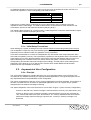
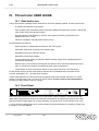
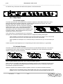
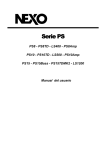
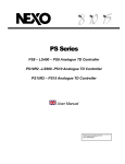
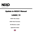
The specific dispersion of the PS10 & PS15 horn can be seen on figure 1 ("front of house" configuration) :
as seen on the side view, vertical coverage is narrower above horn axis (+25°) than below (-30°).
as seen on the front view, horizontal coverage is narrower above horn axis (50° Horizontal for
+25° Vertical) and wider below (100° Horizontal for -30° Vertical). Between these two extremes
horizontal coverage varies according to a specific law ; on axis (0° Vertical) coverage is 75°
Horizontal.
User Manual
Release : 1.31
Date : 29/09/2005
PS10
PS10TD
LS500
PS15
PS15TD
LS1000
LOUDSPEAKERS
p.6
___________________________________________________________________________________________________
Access to the horn for configuration and checking is easily made with the quick release function of the
front grille.(just pull it out). To modify horn orientation remove the four Allen screws that maintain the horn
(Allen 4 metric). A sticker on the wide dispersion side of the horn shows the correct orientation for wedge
monitoring and front of house application : you just have to read the indication on the right side. The
arrow indicate the wide dispersion.
II.2.b. « Front of house » Configuration
50˚
+25˚
-30˚
100˚
Figure 1 : PS15 used « front of house »
Good coverage of
audiences often requires a conflicting
combination of wide coverage ("shortthrow") for the closest listeners (below
cabinet axis) and narrow coverage
("long-throw") for distant areas (on or
above axis). The PS Series horizontal
horn coverage varies from "short-throw"
to "long-throw" along the vertical axis to
precisely match these practical
requirements in a single system. For the
majority of applications the asymmetrical
horn should be used with its "wide"
dispersion side directed towards the floor
(as shown by the arrow) but all four
cabinet orientations are usable.
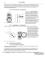
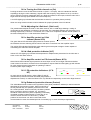
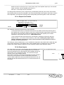
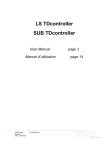
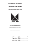
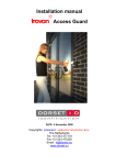
II.2.c. « Stage Monitor » Configuration
For stage monitors the required coverage is always wider when performers are close to the wedge
+3
(above the horn axis) than when
0˚
they move away from it (below the
horn axis). For floor monitor use
the horn must be rotated with its
100˚
"wide" dispersion side directed
-2
towards the top of the cabinet (as
5˚
shown by the arrow) in wedge
position as shown in the above
figure. The specific dispersion
pattern, the 2" driver and the very
high power handling all contribute
to the exceptional performance of
the PS15 as a wedge monitor.
50˚
Figure 2 : PS15 used as a stage monitor
II.3. Subbass Use (optional)
II.3.a. General Recommendations
The Subbass section of the TDcontroller is monophonic (a summation of the Left and Right channels is
made at the input of the Controller).
If an installation uses subbass in Stereo Subbass (this implies the presence of 2 TDcontrollers) do not
forget that when one input only of the Controller is used this will lower the gain of the Sub Output by -6
dB. You can either increase the gain setting of the LSub with the front panel level control or use a Y
adapter to feed both inputs of the controller with the same signal.
User Manual
Release : 1.31
Date : 29/09/2005
PS10
PS10TD
LS500
PS15
PS15TD
LS1000
LOUDSPEAKERS
p.7
___________________________________________________________________________________________________
For best results the LSubs should be as close as possible to the main loudspeakers and aligned with
respect to the audience. This is to avoid interference around the crossover point (around 120 Hz for
PS10/LS500, 75 Hz for PS15/LS1000).
Although this can be at the expense of the above requirement, LSubs' low frequency performance is
enhanced if multiple subs are grouped together. This also applies to Stereo installations using mono
LSub output where left and right Subs can be grouped in the center.
The nominal efficiency data for LS500 and LS1000 and the standard Sub level settings on the
TDcontroller are for LSubs positioned on the floor (half-space). For other system configurations, and
particularly for « flying » subs Subbass:, the low frequency sound pressure can be -3 to -6 dB lower. This
will be compensated by a higher setting on the LSub output level control and/or by adding more subbass
units.
II.4. Accessories
II.4.a. Stand, Mast & U Coupler
PS10s and PS15s have a built in stand adapter (35 mm diameter). Cabinets can be positioned directly on
a general purpose speaker stand or on a mast inserted in the built in stand adapter on top of the LS500 &
LS1000. The U-Coupler accessory allows positioning and relative rotation of two cabinets arrayed side by
side on top of the mast or on a speaker stand. The mast and U-coupler for the PS10 are available as
options (STDUPS10). The U-coupler for the PS15 was not yet available at the time of writing this manual.
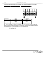
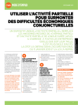
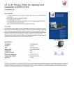
II.4.b. Flying rails Accessories & Rings
PS10s and PS15s are equipped with steel anchor plates (standard) that can be fitted with the following
fittings(optional) :
PS10
Top : 6 position aircraft flying
rail.
Bottom : two single position
round aircraft flying rails.
PS15
Figure 3
Top : 9 position aircraft flying rail.
Bottom : two 3 position aircraft flying rails.
These rails are supplied as part of optional flying kits Accessories containing all necessary screws and 4
single stud aircraft flying rings. Heavy duty double stud flying rings can be used in all rails except the
bottom PS10 points. Installation requires a metric N°5 Allen key (to remove the original backplate screws)
and a metric N°4 Allen key to mount the rails.
Vertical orientation of cabinets is a function of ring position in the top rail. It is imperative for security
reasons to use two rings per rail (left figure) linked to two independently fixed straps. Ring B will also be
used to stabilize the cabinet rotation and reduce the angle given by the master ring A. Nominal vertical
angles relative to the position of ring A (without the influence of ring B) are as follows :
User Manual
Release : 1.31
Date : 29/09/2005
PS10
PS10TD
LS500
PS15
PS15TD
LS1000
LOUDSPEAKERS
p.8
___________________________________________________________________________________________________
Position
1 (see Figure 3)
2
3
4
5
6
7
8
9
PS10 Angles PS15 Angles
-17°
-20°
-12°
-16°
-7°
-12°
-2°
-8°
+3°
-4°
+8°
0°
NA
+4°
NA
+8°
NA
+12°
1
II.4.c. Omnimount® style clamps
The back and the bottom of the PS10 as well as the bottom of the PS15 are equipped with internal
anchor points (M8 metric) to the Omnimount® 100 Series spacing standard. This is particularly
convenient when cabinets must be installed permanently in horizontal or vertical position. To remove the
original screws a N°4 metric Allen key is required.
II.5. Use & Maintenance
II.5.a. Checking the PS10 & PS15 internal fuses
The function of these fuses is to protect the passive crossover against overheating if a speaker
component is accidentally disconnected or goes open circuit. They can also protect amplifiers from
current overloading in that event. To preserve sound quality they are not inserted in series with the
loudspeakers themselves and do not thus protect them. The fuses are located on the PCB of the internal
passive crossover located right behind the connection panel.
If a loudspeaker component gets accidentally disconnected or goes open circuit and needs repairing, the
fuses condition must be checked. They can be verified visually and are easy to replace. These fuses are
of the common "automotive" type (ATO Blade type) with standard values.
Beware : a broken fuse will degrade sound quality and endanger the loudspeaker components but the
cabinet will still operate. It is thus not immediately noticeable. The incidents that can cause fuse break
need cabinet opening anyway, it is good practice to quickly check the fuses on that occasion.
To access the fuses, release the 4 or 6 screws holding the connection panel (Allen metric 2.5) and
disengage the panel & crossover assembly (an upward rotation movement is required).
II.5.b. Troubleshooting
Simple troubleshooting does not need the measurement equipment necessary for maintenance and can
easily be made by users. The first question to be answered is always the identification of the faulty link :
source, controller, amplifier, loudspeaker or cable ? Most installations are Stereo, it is often the case that
one channel works and the other does not. Permutations of successive left and right elements can
usually help locating the fault.
Some cabinet faults can be quite easily located and corrected by the user. A simple sweep with a sine
wave generator can be very helpful but it MUST be made at fairly low level not to endanger speakers :
vibrations due to loosened screws.
air-leak noises : check that no screws are missing, particularly on the flying & fixing accessories
backplates.
User Manual
Release : 1.31
Date : 29/09/2005
PS10
PS10TD
LS500
PS15
PS15TD
LS1000
AMPLIFIERS
p.9
___________________________________________________________________________________________________
vibrations due to a front grille badly positioned in its quick release fixings.
Some faults require opening the cabinet :
fuses (refer to above paragraph)
alien object fallen into the cabinet after repair or through the port holes.
internal connection wires or absorbing material hitting against the loudspeaker diaphragm : check
by removing the bass loudspeaker ( Allen metric N°4).
loudspeaker not connected or phase reversed following a previous inspection, test or repair.
II.5.c. Maintenance & Warranty
Actual servicing requires the facilities and approval of the NEXO dealer or distributor. Please contact him
for any practical information on maintenance. Warranty conditions, rights and disclaimers may vary from
country to country.
III. AMPLIFIERS
III.1. Recommended Power
For best results, NEXO specifies a range of amplifier powers relative to the capacity of the cabinets (see
technical specifications for the PS10, PS15, LS500 & LS1000 pages 19&23). The use of amplifiers with
lower power ratings has no justification other than budgetary. On the contrary, high power amplifiers
(within reasonable limit) present no real technical problem (bearing in mind the servo-control system
which limits the delivered power when needed), but may simply represent an unnecessary expense.
III.2. Current Capability
When evaluating an amplifier, it is important to take account of its behavior under low load conditions
(current capacity) : a speaker system is highly reactive, with transient signals like music it can require a
lot more current than the nominal impedance would indicate. Apart from the manufacturers’
specifications, it is possible to test the amplifier with two times the intended number of cabinets (two
cabinets per channel in place of one, four in place of two, etc..), and drive the system to the onset of
clipping. If there is no noticeable (audible) signal degradation, the amplifier is well suited (do not take
much notice of amplifier heating after several minutes but amplifier protection should not appear too
quickly).
III.3. Gain
It is very important that all the amplifiers within an installation have closely matched gains ; the variation
allowed must be less than +/- 0.5 dB. This precaution is very important for reliability in the case where
only one PS TDcontroller is being used for several cabinets. It is also recommended to use the same
amplifiers throughout and to check their gain periodically. If some different amplifiers must be mixed (e.g.
in rental situations), at least check their gain and adjust as necessary.
NEXO recommends the use of low gain amplifiers whenever possible, 26 dB being the preferred value as
it is quite common. The use of high-gain amplifiers has a negative effect in terms of signal to noise ratios :
the delivered noise is increased whilst the maximum voltage level remains the same (4.5 V peak at the
input is enough to drive a 26 dB gain, 500 W/ 8 Ohm power amplifier to the onset of clipping). The correct
use of the back panel PS TDcontroller output level switch prevents excessive degradation of the signalto-noise ratio by compensating for high gain amplifiers.
User Manual
Release : 1.31
Date : 29/09/2005
PS10
PS10TD
LS500
PS15
PS15TD
LS1000
TDcontroller USER GUIDE
p.10
___________________________________________________________________________________________________
IV. TDcontroller USER GUIDE
IV.1. Read before use
The PS TDcontroller is designed to be used with PS and LSub speaker cabinets. Its main functions are :
to optimize the response of the system
when operating with a Sub-bass system (optional), splitting the signal into 2 frequency bands (PS
main system and Lsub Sub-bass system)
active protection of the cabinets by dynamic Audio signal processing (Temperature and
Displacement servo control)
reduction of amplifier overload (Peak limiter function)
PS TDcontroller also features :
stereo operation (2 independent channels) for the main system
switchable output level according to the amplifier gain
adjustable level on the Sub-bass channel
balanced input and output stages
enhanced protection facility provided for additional safety margin when extended periods of
overload are anticipated
fall-back servo control mode preventing lack of protection when sense lines are disconnected
(NB : on PS10TD, this feature is provided only after serial number #361).
compensation of power compression effects on the system response curve (PS15 only).
As with similar devices, the PS TDcontroller is intended to be inserted between the Audio source
(console, preamplifier, etc...) and the power amplifier.
Unless stated otherwise, the PS TDcontroller is shipped ready to be used with 220-240 V AC mains
voltage. It will also work under 110-120 V AC mains voltage, but this requires internal adjustment.
(Consult your Nexo dealer or service manual)
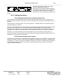
IV.2. Front Panel
LSub 1000
Amp
On
Sense
Protect
Pk
VLF
Amp
Sense
Protect
Pk
LF
Amp
HF
Sense
Protect
Pk
LF
HF
Std
Sub Level
Max
Protect
Left
Right
Most front panel functions and indicators are located inside 2 distinct windows : left-hand areas (with
upper label LSub) relates to functions and indicators dedicated to the optional Sub-bass section, while
right-hand window (upper label TD) contains indicators concerning servo control operation for the PS.
For more technical details about servo control operation and internal electronic processing, please refer
to section V.V.2 of this Manual.
User Manual
Release : 1.31
Date : 29/09/2005
PS10
PS10TD
LS500
PS15
PS15TD
LS1000
TDcontroller USER GUIDE
p.11
___________________________________________________________________________________________________
IV.2.a. Turning the LSub channel on (On)
Pushing the button turns the Sub-bass channel on (Sub L + R output), which is intended to feed the
amplifier(s) driving the LSub cabinet(s). Signals within the frequency range below 75 Hz (or 120 Hz in
case of PS10TD) are then reassigned after Left + Right summation to this output, while the main Left &
Right channels are high-pass filtered at this same frequency.
A red LED lighting up indicates that the Sub-bass channel is in operation (button pushed).
When not using Subs this button must be released for proper operation of the PS cabinet.
IV.2.b.Adjusting the LSub level (Sub Level)
The potentiometer adjusts the level on Sub-bass channel, with a 12 dB range allowing a variety of
configurations and application conditions to be matched. The 2 standard positions are pictured by icons
showing respectively 1 LSub for 1 PS cabinet, and 1 LSub for 2 coupled PS cabinets. Center position of
the knob is adequate for 1 LSub used with 2 distant PS.
IV.2.c. Amplifier control on LSub
channel (Sense & Pk)
On
Sub Level
The green Sense LED indicates signal presence at sense input on
the Sub-bass channel, allowing visual control of the return connection from the amplifier output.
The red Pk LED indicates Peak limiter action reducing excessive peak voltage or levels capable of
overloading the Sub-bass channel amplifier.
IV.2.d.LSub protection indicator (VLF)
Yellow VLF LED lighting up indicates that temperature or displacement protections for the LSub are in
action on the Sub-bass channel.
IV.2.e. Amplifier control on PS channels(Sense & Pk)
Green Sense LEDs indicate signal presence at sense input on Left and on Right channels and allow
visual control of the return connection from the amplifiers’ outputs. Red Pk LEDs lighting up will indicate
for each channel that the Peak limiter is operating to reduce
excessive peak output voltages.
IV.2.f. PS protection indicators (LF &
HF)
Amp
Sense
Protect
Pk
LF
On each side of the TD window, yellow LEDs LF and HF
Left
indicate when protection has been activated (temperature or
displacement control) for either the Bass or the Top End driver respectively on the Left or Right channel.
IV.2.g.Enhanced protection trimmer (Protect)
The embedded trimmer located on the right side of front panel (outside the window) is used to lower the
thresholds of the protection system. When turned fully to
the left (marked Std), the speaker protections will be set
for normal operation. When turned fully clockwise (marked
Max), protections will be increased ; e.g. this setting
should be used where the system is operating under badly
Protect
controlled conditions (identical gain for each amp is not
checked, sense lines are not connected,..). Middle
positions of the trimmer can also be used and will be
recommended in cases of extended periods of overload (e.g. in some discotheque applications).
Std
User Manual
Release : 1.31
Date : 29/09/2005
PS10
PS10TD
LS500
PS15
PS15TD
LS1000
Max
HF
TDcontroller USER GUIDE
p.12
___________________________________________________________________________________________________
On PS15TD only, the trimmer also affects the operation of the Peak limiters.
Model :
Serial n :
Sub
+
-
Output Level
+
Syst R
+
Syst L
matched to
Amp gain of:
Fuse
dB
220V=T125mA
110V=T250mA
Sub L+R
Earth lift
Sense IN
(from Amp Terminals)
Syst R
Audio OUT
Syst L
26
38
R
32
(to Amp inputs)
L
Audio IN
(from Source)
IV.3. Rear Panel
IV.3.a. Audio Inputs
The audio inputs are two 3-pin female XLR connectors located in the area labeled Audio IN, L and R
being the left and right channels respectively. Signal is applied between pins 2 and 3, pin 1 being
grounded. When the Controller is linked to a signal source
with balanced outputs, the XLR connections are simply
wired pin to pin (1 to 1, etc..). As a result of the balanced
nature of the outputs (and providing that balancing is
respected by way of the connection to the amplifier), there
is no hot or cold pin - the PS TDcontroller being neutral
regarding the polarity of the signal.
R
Audio IN
(from Source)
In the case where an unbalanced source is connected to
the inputs, the connections should be made as follows to respect the polarity of the signal :
if the amplifiers connected to the outputs of the PS TDcontroller are wired pin 3 hot, connect the
hot pin of the source to pin 3 of the Audio input XLR of the PS TDcontroller.
if the amplifiers are wired pin 2 hot, connect the hot pin of the source to pin 2 of the Audio input
XLR.
In both cases the unused signal pin (2 or 3 respectively) will have to be linked to pin 1 (grounded).
IV.3.b.Audio Outputs
The audio outputs are the three 3-pin male XLRs located in the area labeled Audio OUT. The channel
corresponding to each output connector is identified by the labels Syst L (left channel),Syst R (right
channel), and Sub L+R (mono Sub-bass).
Syst R
Sub L+R
Audio OUT
Syst L
(to Amp inputs)
Signal is applied between pins 2 and 3, pin 1 being connected to ground.
When used with an amplifier with balanced inputs Amplifier, the wiring of the output XLR is simply pin to
pin (1 to 1, etc..), the polarity of the signal being thus respected if the source connected to the input is
also balanced (see previous section).
Where an amplifier with unbalanced inputs Amplifier is used, the connections shall be as follows :
where the source connected to the PS TDcontroller input is pin 3 hot, connect the hot pin of the
amplifier to pin 3 of the PS TDcontroller XLR output connector and the amplifier ground to pin 2.
User Manual
Release : 1.31
Date : 29/09/2005
PS10
PS10TD
LS500
PS15
PS15TD
LS1000
L
TDcontroller USER GUIDE
p.13
___________________________________________________________________________________________________
where the source is wired pin 2 hot, connect the hot pin of the amplifier input to pin 2 of the XLR
output connector, and the amplifier ground to pin 3.
leave pin 1 of the output XLR unconnected.
This wiring method avoids any loss of output level, provided always that the ground of PS TDcontroller
stays floating relative to that of the amplifier -thus care should be taken with regard to the Earth Lift switch
when depressed : the respective signal grounds could possibly be linked together via the mains earth).
IV.3.c. Output Level Switch
Output
Level
matched to
Amp gain of:
dB
26
38
32
The 3 position output level switch has two main purposes :
1/ Once the sense lines are connected, this switch is only used to match the processor gain to
the amplifier gain for optimum signal to noise ratio. Having selected the appropriate output level,
the signal to noise ratio will be preserved whatever the gain of the amplifier (for a broader
explanation of this please refer to III.III.3 : AMPLIFIERS, Gain).
2/ If the sense lines are disconnected, the TDcontroller is operating in fall back mode (see
relevant section : IV.V.2 Servo Control section). In this case, selecting the proper switch
setting is absolutely necessary to ensure correct operation of the protection circuits as
protection will directly depend on it.
The three gain values available are 26, 32 or 38 dB and correspond to the positions left, middle and right
of the switch respectively. If the effective gain of the amplifiers doesn’t correspond to any of the three
positions the closest should be selected. In case of doubt the lesser value should be chosen.
IV.3.d.Sense inputs
The sense inputs of the three channels (left, right and subbass) are arranged on a six pole barrier strip
set into the rear panel within the area labeled Sense IN. The Sense
inputs are intended for the output signals of the amplifiers driving one
cabinet each of the channel being used : PS for the left and right
channel, LSub for the subbass channel.
Sub
Input sense connection is strongly recommended for proper operation
of the servo-control system. On PS10 TDcontrollers with serial
numbers before #360 which are not provided with fall-back mode, the
cabinets will NOT BE PROTECTED AT ALL if the sense lines are not
connected.
User Manual
Release : 1.31
Date : 29/09/2005
PS10
PS10TD
LS500
PS15
PS15TD
LS1000
+
-
Sense
TDcontroller USER GUIDE
p.14
___________________________________________________________________________________________________
Connection is made via the female part - removable - of the connector (supplied with the Controller) as
outlined below :
Channel
Amplifier Output Terminal
Barrier strip connector
PS Left (Syst L)
PS Right (Syst R)
LSub (Sub)
+ (red)
- (black)
+ (red)
- (black)
+ (red)
- (black)
Ö
Ö
Ö
Ö
Ö
Ö
pin 1 (figure)
pin 2
pin 3
pin 4
pin 5
pin 6
NB : The PS TDcontroller is insensitive to the polarity of the wiring of the inputs, contrary to some other
NEXO Controllers. It is highly recommended to read the further information below regarding the wiring of
Sense lines (IV.IV.4.IV.4.a : Recommendations for wiring the Sense lines).
IV.3.e. Earth Lift
User Manual
Release : 1.31
Date : 29/09/2005
PS10
PS10TD
LS500
PS15
PS15TD
LS1000
TDcontroller USER GUIDE
p.15
___________________________________________________________________________________________________
Model :
Serial n :
Fuse
220V=T125mA
110V=T250mA
Earth lift
The push button labeled « Earth Lift » allows
connection (depressed position), or
disconnection (out position) between the signal
ground and the mains earth, which is itself linked
to the chassis. Using this button may help to
eliminate hum due to ground loops created in the
system.
IV.4. Setting-Up Advice
IV.4.a. Recommendations for wiring the Sense lines
The impedance of the sense inputs of the PS TDcontroller being quite high, the currents are low and
therefore ordinary line cable can be used. If the unit is housed in the amp racks an unshielded cable can
be used.
If the Controller is located remotely - at the mixing position - a shielded cable is recommended, without
using the shield as a conductor.
When one of the channels is not being used and the corresponding sense line is disconnected, crosstalk
onto the inactive sense line may in some cases produce signals capable of causing the untimely
illumination of the Sense LED on that channel ; although this phenomenon has no effect on the internal
operation of the Controller, it can be cured by short-circuiting the terminals of the inactive sense line.
Otherwise, it is strongly advised to protect the amplifiers from short-circuits in the sense lines. It is
recommended that a 1 kOhm resistor with a power rating of at least three watts be inserted as close as
possible to the output terminals of the amps.
IV.4.b.Connecting the audio outputs
Output stages are able to drive several amplifiers in parallel ; however it is not advised to work with loads
of less than 1 kOhm. It is best to check with the impedance characteristics of the inputs - supplied by the
manufacturer - to check if the number of amplifier channels is not too many. Where precise information is
not available (and taking 10 kOhm as the minimum value possible) then ten channels in parallel per
output is a sensible maximum.
User Manual
Release : 1.31
Date : 29/09/2005
PS10
PS10TD
LS500
PS15
PS15TD
LS1000
TDcontroller REFERENCE GUIDE
p.16
___________________________________________________________________________________________________
V.
TDcontroller REFERENCE GUIDE
V.1. Linear section
The characteristics of the linear section are independent of signal level, as opposed to the servo control
functions described in next paragraph.
V.1.a. Subsonic and VHF filtering
Low and high-pass filters are used to remove signals not of the usable frequency range and so eliminate
sub- and ultra-sonic components that could possibly degrade the performance of the Controller and
amplifiers. Those filters are optimized for achievement of the target overall system response.
V.1.b. Equalizing acoustical response
This equalizing section achieves the correction required to obtain a flat system response, as the cabinets
are acoustically designed for maximum efficiency on the whole frequency range. Active rather than
passive attenuation allows lowering amplifier voltages for a given output SPL and therefore increases the
maximum SPL achievable with the same amplifier.
Active equalization also extends system bandpass especially at low frequencies where acoustical
performance is limited by cabinet size.
V.1.c. PS / LSub Cross-Over
From input signals summed together, the resulting mono signal is low-pass filtered to feed the Sub-bass
channel. When the channel is turned on (LSub On), main channels (Left & Right) high-pass filters are
reconfigured to filter out signal components below the cross-over frequency. Slopes and other filter
characteristics are optimized using techniques that take into account the actual acoustical data of each
loudspeaker in the cabinets.
V.1.d. LSub operation and level adjustment
When the LSub channel is off, its signal is grounded just before the output stage. When the channel is in
use, the potentiometer adjusts output level by acting on the Sub’s VCA control voltage.
V.1.e. Gain. Output stage
For each of the 3 channels gain is set by an attenuation network simultaneously modified according to
the position of the rear panel output level switch ; nominal gain is unity for the 26 dB position, -6 dB for
the 32 dB position, and -12 dB for 38 dB position (Left & Right channels).
Electronic balance at the output stage reduces spurious noises in case of bad grounding conditions ; an
additional feature of the balanced stage is doubling the voltage swing at the output.
V.2. Servo Control section
Servo control of the PS TDcontroller is normally intended to work with amplifier return signals present at
the Sense inputs (monitored by front panel LEDs).
(WARNING : the following paragraph does not apply to PS10 TDcontrollers with serial numbers below
#361)
However, when no signal is detected on one Sense line, an internal signal is automatically substituted for
the actual amplifier signal at the input of the servo control path. This fall-back operation mode allows
protection to be maintained even when Sense lines are disconnected. It should be nevertheless
emphasized that this operation mode will not perform with the same accuracy and reliability as actual
feedback, and is intended to maintain some protection in accidental situations only.
User Manual
Release : 1.31
Date : 29/09/2005
PS10
PS10TD
LS500
PS15
PS15TD
LS1000
TDcontroller REFERENCE GUIDE
p.17
___________________________________________________________________________________________________
V.2.a. VCAs and VCEQs
Each of the 3 Audio channels (Left, Right and Sub-bass) contains two voltage controlled elements driven
by servo signals :
one operates on the whole frequency range (wide band VCA).
the other element works selectively as a dynamic equalizer (LF-VCEQ).
Depending on the nature and origin of the servo signals, either one or the 2 combined elements is used
to process the Audio signal. This feature allows a more efficient processing while reducing audible
effects.
V.2.b. Displacement control
The signal from the sense input is fed through a shaping filter producing a signal proportional to the voice
coil displacement. This control signal is compared to a fixed value and if exceeded, the LF-VCEQ is
activated with very short attack time to reduce speaker excursion. For even higher levels the control
voltage will also activate the wideband VCA.
V.2.c. Temperature control
Sense input is fed to a shaping filter to create a voltage proportional to the instantaneous voice-coil
current. The signal is integrated over time to simulate heat buildup in the specific driver. When the
resulting voltage exceeds a preset threshold, the VCA is activated to limit the voice coil temperature
within its safety range. Besides, on PS15TD and on PS10TD (serial number above 868), power
compression is simulated by lowering the high frequencies when temperature protection is acting on the
bass loudspeaker.
V.2.d. Dynamic control
To reduce audible « pumping » effects due to very long time constants of temperature detection signals,
an alternate integration is also processed with a shorter time constant. Whilst anticipating the
temperature protection and reducing its unwanted effects, action of this signal also improves dynamics
control.
V.2.e. Peak Limiter
The above mentioned devices provide reliable protection against potential speaker over-heating and
over-excursion. Nevertheless driving the cabinets at very high peak voltages (with oversized amplifiers)
as well as delivering distorted signals might be dangerous for the speakers. The Peak limiter is both
useful for :
maintaining good sound quality at high levels (it will reduce amplifier distortion).
increasing protection reliability (limiting peak voltages to levels that speakers can permanently
withstand, and reducing the occurrence of subsonic signals delivered by overloaded amps).
User Manual
Release : 1.31
Date : 29/09/2005
PS10
PS10TD
LS500
PS15
PS15TD
LS1000
TDcontroller REFERENCE GUIDE
p.18
___________________________________________________________________________________________________
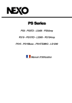
V.3. Electronic block diagram
User Manual
Release : 1.31
Date : 29/09/2005
PS10
PS10TD
LS500
PS15
PS15TD
LS1000
SPECIFICATIONS, CURVES & DIAGRAMS
p.19
___________________________________________________________________________________________________
VI. SPECIFICATIONS, CURVES & DIAGRAMS
VI.1. PS10, PS10TD & LS500
VI.1.a. Specifications
SYSTEM SPECIFICATIONS
PS10 with PS10 TDcontroller
LSub 500 with PS10 TDcontroller
Frequency Response [a]
65 Hz - 20 kHz ±3dB
40 Hz - 110 Hz ±3dB
Usable Range @-6dB [a]
58 Hz - 21 kHz
38Hz - 120 Hz
Sensitivity 1W @ 1m [b]
98 dB SPL Nominal - 96 dB SPL Wideband
101 dB SPL Nominal
Nominal Peak SPL @ 1m [b]
124 to 127 dB Peak (for 200 to 500 W RMS Amp.)
131 to 134 dB Peak (300 to 800 W RMS Amp.)
HF Dispersion [c]
50° to 100° Hor. x 55° Vert. Rotatable Horn, 4 positions
-
Directivity : Q & DI [c]
Q : 16 Nominal
-
DI : 12 dB Nominal ( f > 3 kHz )
Crossover Frequencies
2 kHz Passive
Nominal Impedance
8 Ohms
120 Hz Active through PS10 TD
4 Ohms
Recommended Amplifiers
200 to 500 Watts into 8 Ohms for 1 x PS10 per channel 400
to 1000 Watts into 4 Ohms for 2 x PS10 per channel
300 to 800 Watts into 4 Ohms
SYSTEM OPERATION
Electronic Controller
Dispersion configuration
Subbass
Speaker Cables
The PS10 TDController is precisely matched to the PS10 & LS500 cabinets and includes sophisticated
protection systems. Using PS10 & LS500 without a properly connected PS10 TD will result in poor sound
quality and can damage the components.
After quick-release of the front grille from its fixings, the HF Horn can be rotated in 4 positions for dispersion
configuration.
The PS10 can be used without optional LS500 Subbass. Active two-way operation with the LS500 is included in
the PS10 TD. One LS500 matches 2 x PS10, additional LS500 may be used for enhanced effect.
PS10 are wired 2- & 2+ on Speakon connectors, LS500 on 1- & 1+. Loop through Speakons are present on
both. Single identical cables can thus be used to loop through combinations of up to 2 x PS10 & 1 x LS500 in
no particular order.
PRODUCT FEATURES
PS10
LSub 500
Components : LF
1 x 10" (25cm) 8 Ohm driver
1 x 15" (38cm) long excursion 4 Ohm driver
-
Height x Width x Depth
1 x 1" throat driver + Low Distorsion,
Constant Directivity Asymetrical Dispersion Horn.
515 x 316 x 277 mm (20.28"x 12.44"x 10.91")
Weight : Net
15 kg (33 Lbs)
430 x 689 x 528 mm
20.79")
33 kg (73 Lbs)
Connectors
2 x NL4MP Speakon 4 pole
2 x NL4MP Speakon 4 pole
Construction
Baltic Birch Ply finished with structured black coating
Baltic Birch Ply & structured black coating
Fittings:
Handles
2 Metal recessed pockets
2 Metal recessed pockets
Front finish
Acoustic foam on hex perforated steel grille (77%
transparent)
1 steel anchor plate for flying track on top (6 positions).
2 steel anchor plates for flying tracks on bottom (1 position)
Built in Steel Stand Fitting, 35mm (1"3/8)
Perforated steel grilles
[VLF]
HF
Flying Points
Stand fittings
Fixed Installation
User Manual
Release : 1.31
Date : 29/09/2005
Two sets of 4 fixing points (Omnimount 100 Std spacing)
for Horizontal or Vertical installation.
PS10
PS10TD
LS500
PS15
PS15TD
LS1000
(16.93"x 27.13"x
3 steel anchor plates for flying
tracks on sides and back
Internal Steel Stand Fitting on Top (35mm,
1"3/8) accepts a mast supporting 1 or 2 PS10's.
-
SPECIFICATIONS, CURVES & DIAGRAMS
p.20
___________________________________________________________________________________________________
PRODUCT FEATURES
PS10 TDController
Audio Inputs
Two L&R Audio inputs. Electronically balanced, 36 kOhm. Two XLR-3F connectors.
Sense Inputs
Three Amplifier Sense Inputs (PS10 L&R, LS500). 150 kOhm. 6 Pole Removable Strip Terminal.
Audio Outputs
Power Supply
Two L&R PS10 Audio outputs. Electronically balanced, 50 Ohm. Two XLR-3M.
One Mono (L+R) LS500 Audio output. Electronically balanced, 50 Ohm. One XLR-3M.
Output Level : +20 dBm Max. +19dBm Max on 1kOhm
Noise : -88 dBm (22 Hz - 22 kHz, UnWeighted). THD+N : < 0.03% Typ. 0.05 Max for +18dBm Output
Std/Max Protection Trimmer. Gain switch (back panel), 3 positions for Amps with Gain : 26 / 32 / 38 dB.
Sub On switch & Sub Gain Control. Speaker Protect LED's. Amp Sense & Peak LED's.
110/220 Volts (internal wiring), 50/60Hz.
Earth-Lift (back panel)
Dimensions & Weight
1U 19" Rack.
Specifications
Controls & Indicators
190mm (7.5") Depth.
2.9 kg (6.6 Lbs) net
SHIPPING & ORDERING
Packaging
PS10's are packaged as pairs with PS10TD (Ref: PS10P+T) or without PS10TD (Ref : PS10P) in a single box.
Shipping weight & Volume
Ref PS10P : 34 Kg (pair). Ref PS10P+T : 37 Kg (pair+processor). Shipping Volume : 0.169 m3 ( 5.96 cu feet)
Ref LS500 : 38 kg (unit) 0.238 m3 (8.41 cu feet)
Accessories
Flying Kit (Ref: FLYPS10) containing 1 x PS10 Top Rail, 2 x PS10 Bottom Rails, 4 x Single Stud Flying Rings.
Mast Adapter Kit (Ref: STDUPS10) containing 1 m (39") long mast & U coupler supporting 1 or 2 PS10 above
LS500
As part of a policy of continual improvement, NEXO reserves the right to change specifications without notice.
[a] Response curves & data : Anechoïc Far Field for the PS10 + PS10TD. Half-Space Anechoïc radiation for the LS500 + PS10TD.
[b] Sensitivity & Peak SPL data : these will depend on spectral distribution and crest factor of program material. Measured with band limited Pink
Noise. Nominal refers to Voice Decade (300 Hz - 3 kHz), Wideband to the specified ±3dB range. Data are for speaker + processor + recommended
amplifier combinations. Peak SPL is at clipping of recommended amplifier.
[c] Directivity curves & data : obtained by computer treatment on off axis response curves.
Omnimount is a registered trade mark of Omnimount Systems Inc.
VI.1.b.Dimensions
User Manual
Release : 1.31
Date : 29/09/2005
PS10
PS10TD
LS500
PS15
PS15TD
LS1000
SPECIFICATIONS, CURVES & DIAGRAMS
p.21
___________________________________________________________________________________________________
VI.1.c. Curves
TOTAL DISTORSION (%)
ON AXIS RESPONSE (dB)
10
10.000
0.0
1
-10.00
-20.00
0.1
-30.00
30
100
1k
10k
30
20k
c 1 : On axis responses PS10 & PS10 + LS500
100
1k
10k
20k
c 2 : PS10 + LS500 : THD for 110 dBSPL @ 1m.
IMPEDANCE (Log Z)
30.000
-Horizontal polar plots (left)
upper plot : vertical orientation +25°
center plot : vertical orientation 0°
lower plot : vertical orientation -25°
-Vertical polar plot (right)
5 dB / div
24.000
18.000
12.000
6.0000
30
100
1k
10k
20k
c 3 : Impedance PS10 and LS500
0°
30°
30°
OFF-AXIS RESPONSE (dB)
10.000
60°
60°
0.0
16037 Hz
10085 Hz
5086 Hz
90°
90°
-10.00
120°
120°
-20.00
100
1k
10k
20k
c 4 : Horizontal plane, vertical orientation +25°.
10°(black),20°(light),30°(dark) off axis response
150°
150°
OFF-AXIS RESPONSE (dB)
180°
10.000
0°
30°
90°
30°
120°
60°
0.0
60°
60°
30°
150°
-10.00
16037 Hz
10085 Hz
5086 Hz
90°
-20.00
100
1k
10k
c 5 : Horizontal plane, vertical orientation 0°.
20°(black),30°(light),40°(dark) off axis response
16037 Hz
10085 Hz
5086 Hz
90° 180°
20k
120°
120°
0°
150°
30°
OFF-AXIS RESPONSE (dB)
10.000
150°
150°
120°
60°
90°
180°
0°
0.0
30°
-10.00
30°
60°
60°
16037 Hz
10085 Hz
5086 Hz
-20.00
100
1k
10k
20k
90°
c 6 : Horizontal plane, vertical orientation -25°.
30°(black),40°(light),50°(dark) off axis response
90°
COVERAGE ANGLES (ł)
200
DIRECTIVITY INDEX (dB) & Q
20.000
100
120°
120°
100
15.000
150°
150°
180°
10.000
10
5.0000
20
100
0.0
1k
c7 : Directivity index and factor.
User Manual
PS10
Release : 1.31
PS10TD
Date : 29/09/2005
LS500
10k
1k
10k
c 8 : Horizontal (light) and vertical (black)
coverage angles, -6dB points.
1
100
20k
PS15
PS15TD
LS1000
20k
SPECIFICATIONS, CURVES & DIAGRAMS
p.22
___________________________________________________________________________________________________
VI.1.d.Connection Diagrams
Configuration with one PS10 per side and one LS500
User Manual
Release : 1.31
Date : 29/09/2005
PS10
PS10TD
LS500
Configuration with two PS10 per side and one
LS500 per side
PS15
PS15TD
LS1000
SPECIFICATIONS, CURVES & DIAGRAMS
p.23
___________________________________________________________________________________________________
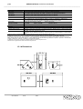
VI.2. PS15, PS15TD & LS1000
VI.2.a. Specifications
SYSTEM SPECIFICATIONS
PS15 with PS15 TDcontroller
LSub 1000 with PS15 TDcontroller
Frequency Response [a]
50 Hz - 18 kHz ±3 dB
30 Hz - 120 Hz ±3 dB
Usable Range @-6 dB [a]
47 Hz - 18 kHz
29 Hz - 130 Hz
Sensitivity 1W @ 1m [b]
102 dB SPL Nominal. 99 dB SPL Wideband
102 dB SPL Nominal
Nominal Peak SPL @ 1m [b]
131 to 134 dB Peak (for 550 to 1200 W RMS Amp.)
HF Dispersion [c]
50° to 100° Hor. x 55° Vert. Rotatable Horn - 4 positions
133 to 135 dB Peak (800 to 1200 W RMS
Amp.)
-
Directivity : Q & DI [c]
Q : 16 Nominal
-
Crossover Frequencies
900 Hz Passive or Active (internally switchable)
80 Hz Active through PS15 TD
Nominal Impedance
Passive : 8 Ohms or Active : LF : 6 Ohms & HF : 8 Ohms
4 Ohms
Recommended Amplifiers
550 to 1200 Watts into 8 Ohms for 1 x PS15 per channel
1000 to 1800 Watts into 4 Ohms for 2 x PS15 per channel
800 to 1200 Watts into 4 Ohms
-
DI : 12 dB Nominal
( f > 1.5 kHz )
SYSTEM OPERATION
Electronic Controller
Dispersion configuration
Subbass
The PS15 TDcontroller is precisely matched to the PS15 & LS1000 cabinets and includes protections. Using
PS15 & LSub's without a properly connected PS15 TD will result in poor sound quality and can damage the
components.
The PS15 TDcontroller cannot be used with PS15's switched to two-way active operation mode. Another
type of NEXO processor is required for this application.
After quick-release of the front grille from its fixings, the HF Horn can be rotated in 4 positions for dispersion
configuration.
The PS15 can be used without optional Subbass. Active operation of the LS1000 is included in the PS15 TD.
Speaker Cables
PS15 are wired 2- & 2+ on Passive Input Speakons, LS1000 on 1- & 1+. Loop through Speakons are present
on both. Single identical cables can thus be used to loop through combinations of PS15 in passive & LS1000 in
no particular order.
PRODUCT FEATURES
PS15
LSub 1000
Components :LF
1 x 18" (46 cm) long excursion 4 Ohm driver
-
Height x Width x Depth
1 x 15" (38 cm) 6 Ohms proprietary
1 x 2" throat, 3" Titanium diaphragm, driver + Low Distortion,
Constant Directivity Asymmetrical Dispersion Horn.
675 x 434 x 368 mm (26.57"x 17.08"x 14.48")
Weight : Net
29 kg (64 Lb.)
515 x 791 x 597 mm (20.28"x 31.14"x 23.50")
Dimensions of 2 stacked LS1000 = 1 x LS2000
45 kg (99 Lb.)
Speakon Connectors
2 x 4 pole (Passive In & Loop Thru) + 1 x 4 Pole (Active In)
2 x 4 pole (In & Loop Thru)
Construction
Baltic Birch Ply finished with structured black coating
Baltic Birch Ply & structured black coating
Fittings:
Handles
2 Metal recessed pockets
2 Metal recessed pockets
Front finish
Perforated steel grilles
Stand fittings
Acoustic foam on hex perforated steel grille (77%
transparent)
1 steel anchor plate for flying track on top (9 positions).
2 steel anchor plates for flying tracks on bottom (3 positions)
Built in Steel Stand Fitting, 35 mm (1"3/8)
Fixed Installation
One set of 4 fixing points (Omnimount 100 Std spacing)
[Sub]
HF
Flying Points
User Manual
Release : 1.31
Date : 29/09/2005
PS10
PS10TD
LS500
PS15
PS15TD
LS1000
3 steel anchor plates for flying tracks on sides
and back
Internal Steel Stand Fitting on Top (35 mm,
1"3/8) accepts a mast supporting 1 or 2 PS15's.
SPECIFICATIONS, CURVES & DIAGRAMS
p.24
___________________________________________________________________________________________________
PRODUCT FEATURES
PS15 TDcontroller
Audio Inputs
Two L&R Audio inputs. Electronically balanced, 36 kOhm. Two XLR-3F connectors.
Sense Inputs
Three Amplifier Sense Inputs (PS15 L&R, LS1000/2000). 150 kOhm. on 6 Pole Removable Strip Terminal.
Audio Outputs
Power Supply
Two L&R PS15 Audio outputs. Electronically balanced, 50 Ohm. On two XLR-3M.
One Mono (L+R) LS1000/2000 Audio output. Electronically balanced, 50 Ohm. On one XLR-3M.
Output Level : +22 dBm Max.
+21 dBm Max. on 1 kOhm
Noise : -86 dBm (22 Hz - 22 kHz, Unweighted). THD+N : < 0.03% Typ. 0.05% Max. for +20 dBm Output
Std/Max. Protection Trimmer. Gain switch (back panel), 3 positions for Amps with Gain : 26 / 32 / 38 dB.
Sub On switch & Sub Gain Control. Speaker Protect LED's. Amp Sense & Peak LED's.
110/220 Volts (internal wiring), 50/60 Hz.
Earth-Lift (switch on back panel)
Dimensions & Weight
1U 19" Rack.
Specifications
Controls & Indicators
190 mm (7.5") Depth. 2.9 kg
(6.6 Lb.) net
SHIPPING & ORDERING
Packaging
PS15's are sold as pairs with PS15TD (Ref.: PS15P+T) or without PS15TD (Ref.: PS15P).
Shipping weight & Volume
PS15 : 32 Kg (70 lb.) 0.2 cum (7 cu feet).
PS15 TD : 3.3 Kg (7 lb.) 0.02 cu m (0.6 cu feet)
Ref. LS1000 : 49 kg (108 lb.)0.32 cu m (11 cu feet)
Accessories
Flying Kit (Ref.: FLYPS15) containing 1 x PS15 Top Rail, 2 x PS15 Bottom Rails, 4 x Single Stud Flying Rings.
Mast Adapter Kit (Ref.: STDUPS15) containing 1 m (39") long mast & U coupler supporting 1 or 2 PS15 above
LS1000.
As part of a policy of continual improvement, NEXO reserves the right to change specifications without notice.
[a] Response curves & data : Anechoic Far Field for the PS15 + PS15TD. Half-Space Anechoic radiation for the LS1000 + PS15TD.
[b] Sensitivity & Peak SPL data : these will depend on spectral distribution and crest factor of program material. Measured with band limited Pink
Noise.
Nominal refers to Voice Decade (300 Hz - 3 kHz), Wideband to the specified ±3 dB range. Data are for speaker + processor + recommended amplifier
combinations. Peak SPL is at clipping of recommended amplifier. Measurements made with PS15's in passive operation mode.
[c] Directivity curves & data : obtained by computer treatment on off axis response curves.
Omnimount is a registered trade mark of Omnimount Systems Inc.
VI.2.b.Dimensions
User Manual
Release : 1.31
Date : 29/09/2005
PS10
PS10TD
LS500
PS15
PS15TD
LS1000
SPECIFICATIONS, CURVES & DIAGRAMS
p.25
___________________________________________________________________________________________________
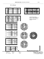
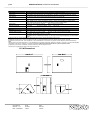
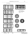
VI.2.c. Curves
TOTAL DISTORSION (%)
ON AXIS RESPONSE (dB)
10.000
10
0.0
-10.00
1
-20.00
-30.00
0.1
30
100
1k
10k
20k
30
c 9 : On axis responses PS15 & PS15 + LS1000
100
1k
10k
20k
c 10 : PS15 + LS1000 : THD for 115 dBSPL @ 1m.
IMPEDANCE
32 Ohm
-Horizontal polar plots (left)
upper plot : vertical orientation +25°
center plot : vertical orientation 0°
lower plot : vertical orientation -25°
-Vertical polar plot (right)
5 dB / div
16 Ohm
8 Ohm
4 Ohm
2 Ohm
30
100
1k
10k
20k
c 11 : Impedance PS15 and LS1000
0°
30°
30°
OFF-AXIS RESPONSE (dB)
10.000
60°
60°
10000 Hz
5000 Hz
2500 Hz
0.0
90°
90°
-10.00
120°
120°
150°
-20.00
100
1k
10k
20k
150°
180°
c 12 : Horizontal plane, vertical orientation +25°.
10°(black),20°(light), 30°(dark) off axis response
0°
90°
30°
30°
120°
60°
OFF-AXIS RESPONSE (dB)
10.000
60°
60°
0.0
10000 Hz
5000 Hz
2500 Hz
90°
150°
30°
10000 Hz
5000 Hz
2500 Hz
90° 180°
0°
-10.00
120°
120°
30°
150°
-20.00
100
1k
10k
20k
150°
c 13 : Horizontal plane, vertical orientation 0°.
20°(black),30°(light),40°(dark) off axis response
150°
120°
60°
90°
180°
0°
30°
OFF-AXIS RESPONSE (dB)
30°
10.000
60°
60°
0.0
10000 Hz
5000 Hz
2500 Hz
90°
90°
-10.00
120°
120°
-20.00
100
1k
10k
20k
150°
c 14 : Horizontal plane, vertical orientation -25°.
30°(black),40°(light),50°(dark) off axis response
150°
180°
COVERAGE ANGLES (Degree)
200
DIRECTIVITY INDEX (dB) & Q
20.000
100
100
15.000
10.000
10
5.0000
20
100
0.0
1k
10k
20k
c15 : Directivity index and factor.
User Manual
Release : 1.31
Date : 29/09/2005
PS10
PS10TD
LS500
1k
10k
c 16 : Horizontal (light) and vertical (black)
coverage angles, -6dB points.
1
100
PS15
PS15TD
LS1000
20k
SPECIFICATIONS, CURVES & DIAGRAMS
p.26
___________________________________________________________________________________________________
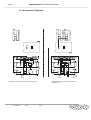
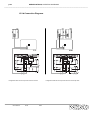
VI.2.d.Connection Diagrams
Ω
Ω
Ω
Ω
Ω
Configuration with one PS15 per side and one LS1000.
User Manual
Release : 1.31
Date : 29/09/2005
PS10
PS10TD
LS500
Ω
Ω
Configuration with two PS15 per side and one LS1000 per side
PS15
PS15TD
LS1000
INDEX
p.27
___________________________________________________________________________________________________
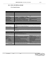
VII. INDEX
A
P
Accessories......................................................................... 7
flying kits....................................................................... 7
flying rails...................................................................... 7
stand............................................................................... 7
Amplifier............................................................................ 9
balanced inputs ............................................................ 12
current capability ........................................................... 9
gain ................................................................................ 9
recommended power...................................................... 9
unbalanced inputs ........................................................ 12
Asymmetrical horn............................................................. 5
« Front of house » .......................................................... 6
« Stage Monitor » .......................................................... 6
Principle......................................................................... 5
Peak Limiter .....................................................................16
polar plots...................................................................20; 24
Protection trimmer ............................................................11
D
Diagram
connection.............................................................. 21; 25
curves..................................................................... 20; 24
Electronic block ........................................................... 17
Dimensions................................................................. 19; 23
Displacement control ....................................................... 16
Dynamic control............................................................... 16
S
Sense
inputs............................................................................13
lines ..............................................................................13
Sense lines ........................................................................13
Setup Precautions ...............................................................5
Speaker wiring....................................................................4
Speakon ..............................................................................4
Specifications..............................................................18; 22
Sub Level..........................................................................11
Subbass ...............................................................................6
« flying » subs ................................................................7
stereo ..............................................................................6
T
Earth lift ........................................................................... 13
TDcontroller ...........................................................4; 10; 15
Front Panel ...................................................................10
Rear Panel ....................................................................12
warning! .........................................................................4
Temperature control..........................................................16
Troubleshooting..................................................................8
Two-way active ..............................................................4; 5
F
U
Fuses (passive crossover) ................................................... 8
Unbalanced source............................................................12
M
V
Maintenance ....................................................................... 8
VCA..................................................................................16
VCEQ ...............................................................................16
E
O
W
Omnimount ........................................................................ 8
Output Level .................................................................... 13
User Manual
Release : 1.31
Date : 29/09/2005
PS10
PS10TD
LS500
PS15
PS15TD
LS1000
Warranty .............................................................................9