1
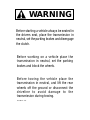
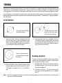
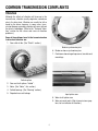
Fuller® Heavy Duty Transmissions
More time on the road®
Troubleshooting Guide
Fuller Heavy DutyTransmissions
TRTS0910
October 2007
FR-11210B
FRO-16210B
RTLO-11610B-T2
RTLO-16713A
FR-12210B
FRO-16210C
RTLO-12610B
RTLO-16713A-T2
FR-13210B
FRO-17210C
RTLO-12610B-T2
RTLO-16718B
FR-14210B
FRO-18210C
FR-15210B
FROF-11210B RTLO-12913A
RTLO-12713A
RTO-11607LL
RTOF-11707LL
RTX-11610
RTX-13609A
RTX-15710B
RTXF-12515
RTLOF-11610B-T2 RTLOF-16713A-T2
RTO-11607LL
RTOF-11708LL
RTX-11615
RTX-13609B
RTX-15710C
RTXF-12609A
RTLOF-12610B
RTO-11608LL
RTOF-11709MLL RTX-11708LL
RTX-13609P
RTX-15715
RTXF-12609B
RTLOF-11610B
RTLOF-16713A
RTLOF-16718B
RTLO-16913A
RTLOF-12610B-T2 RTLOF-16913A
RTO-11707DLL RTOF-11908LL
RTX-13609R
RTX-16709B
RTXF-12609P
RTLO-16913A-T2
RTLOF-12713A
RTLOF-16913A-T2
RTO-11707LL
RTOF-11909ALL
RTX-11709B
RTX-13709H
RTX-16709H
RTXF-12609R
RTOF-11909MLL RTX-11709H
RTX-13710B
RTX-16710B
RTXF-12610
RTX-13710C
RTX-16710C
RTXF-12709H
RTX-14608LL RTXF-11509
RTXF-12710B
FR-9210B
FROF-11210C RTLO-13610B
RTLO-16918B
RTLOF-12913A
RTLOF-16918B
RTO-11708LL
FRF-11210B
FROF-12210B RTLO-13610B-T2
RTLO-16918B-T2
RTLOF-13610B
RTLOF-16918B-T2
RTO-11709MLL RTOF-13707DLL
RTX-11709A
RTX-11710B
FRF-12210B
FROF-12210C RTLO-14610A
RTLO-17610B
RTLOF-13610B-T2 RTLOF-17610B
RTO-11908LL
FRF-13210B
FROF-13210B RTLO-14610B
RTLO-17610B-T2
RTLOF-14610B
RTO-11909ALL RTOF-14608LL
RTX-11715
RTX-14609A
RTXF-11608LL RTXF-12710C
FRF-14210B
FROF-13210C RTLO-14610B-T2
RTLO-18610B
RTLOF-14610B-T2 RTLOF-18610B
RTO-11909MLL RTOF-14708LL
RTX-12509
RTX-14609B
RTXF-11609A RTXF-13609A
FRF-15210B
FROF-14210B RTLO-14613B
RTLO-18610B-T2
RTLOF-14613B
RTLOF-18718B
RTO-13707DLL RTOF-14709MLL RTX-12510
RTX-14609P
RTXF-11609B RTXF-13609B
RTX-12515
RTLOF-17610B-T2
RTOF-13707MLL RTX-11710C
FRF-9210B
FROF-14210C RTLO-14618A
RTLO-18718B
RTLOF-14618A
RTLOF-18913A
RTO-13707MLL RTOF-14908LL
RTX-14609R
RTXF-11609P
FRO-11210B
FROF-15210B RTLO-14713A
RTLO-18718B-T2
RTLOF-14713A
RTLOF-18913A-T2
RTO-14608LL
RTX-12609A
RTX-14610
RTXF-11609R RTXF-13609R
FRO-11210C
FROF-15210C RTLO-14718B
RTLO-18913A
RTLOF-14718B
RTLOF-18918B
RTO-14709MLL RTOF-14909MLL RTX-12609B
RTX-14615
RTXF-11610
RTXF-13709H
FRO-12210B
FROF-16210B RTLO-14913A
RTLO-18913A-T2
RTLOF-14913A
RTLOF-18918B-T2
RTO-14908LL
RTX-12609P
RTX-14708LL RTXF-11615
RTXF-13710B
RTLOF-20913A
RTO-14909ALL RTOF-16909ALL
RTOF-14909ALL
RTOF-16908LL
RTXF-13609P
FRO-12210C
FROF-16210C RTLO-14918B
RTLO-18918B
RTLOF-14918B
RTX-12609R
RTX-14709A
RTXF-11708LL RTXF-13710C
FRO-13210B
FRW-15210B
RTLO-18918B-T2
RTLOF-14918B-T2 RTLOF-20918B
RTO-14909MLL RTX-11509
RTX-12610
RTX-14709B
RTXF-11709H RTXF-14608LL
RTO-16908LL
RTLO-14918B-T2
FRO-13210C
RT-7608LL
RTLO-15610B
RTLO-20913A
RTLOF-15610B
RTX-12709A
RTX-14709H
RTXF-11710B RTXF-14609A
FRO-14210B
RT-8608L
RTLO-15610B-T2
RTLO-20918B
RTLOF-15610B-T2 RTLOF-22918B
RTO-16909ALL RTX-11609A
RTX-12709B
RTX-14710B
RTXF-11710C RTXF-14609B
RTOF-11607L
RTX-11609B
RTX-12709H
RTX-14710C
RTXF-11715
RTXF-14609P
RTOF-11607LL RTX-11609P
RTX-12710B
RTX-14715
RTXF-12509
RTXF-14609R
RTO-11607L
RTOF-11608LL RTX-11609R
RTX-12710C
RTX-15615
RTXF-12510
RTXF-14610
RTXF-15710B
RTXF-15710C
RTXF-16709B RTXF-16709H RTXF-16710B RTXF-16710C
RTLOF-20918B-T2
FRO-14210C
RT-8908LL
RTLO-16610B
RTLO-20918B-T2
RTLOF-16610B
FRO-15210B
RTF-8608L
RTLO-16610B-T2
RTLO-22918B
RTLOF-16610B-T2 RTO-11607L
FRO-15210C
RTF-8908LL
RTXF-14615
RTLO-11610B RTXF-14710C
RTLO-16618A
RTXF-14708LL RTXF-14709H RTXF-14710B
RTLOC-16909A-T2 RTLOF-16618A
RTXF-14715
RTXF-15615
RTLOFC-16909A-T2
RTX-11608LL
RTXF-15715
WARNING
Before starting a vehicle always be seated in
the drivers seat, place the transmission in
neutral, set the parking brakes and disengage
the clutch.
Before working on a vehicle place the
transmission in neutral, set the parking
brakes and block the wheels.
Before towing the vehicle place the
transmission in neutral, and lift the rear
wheels off the ground or disconnect the
driveline to avoid damage to the
transmission during towing.
Cut 8007K - 1/88
TABLE OF CONTENTS
FORWARD . . . . . . . . . . . . . . . . . . . . . . . . . . . . . . . . . . . . . . . . . . . . . . . . . . . . . . . . . . . . . . . . . . . . . . . . . . . . . . . . .
1
POWER FLOW . . . . . . . . . . . . . . . . . . . . . . . . . . . . . . . . . . . . . . . . . . . . . . . . . . . . . . . . . . . . . . . . . . . . . . . . . . . . . .
2
TIMING . . . . . . . . . . . . . . . . . . . . . . . . . . . . . . . . . . . . . . . . . . . . . . . . . . . . . . . . . . . . . . . . . . . . . . . . . . . . . . . . . . .
4
COMMON TRANSMISSION COMPLAINTS . . . . . . . . . . . . . . . . . . . . . . . . . . . . . . . . . . . . . . . . . . . . . . . . . . . . . . . .
5
GEARS AND SHAFTS . . . . . . . . . . . . . . . . . . . . . . . . . . . . . . . . . . . . . . . . . . . . . . . . . . . . . . . . . . . . . . . . . . . . . . . . . 10
BEARINGS . . . . . . . . . . . . . . . . . . . . . . . . . . . . . . . . . . . . . . . . . . . . . . . . . . . . . . . . . . . . . . . . . . . . . . . . . . . . . . . . . 13
TRANSMISSION ALIGNMENT . . . . . . . . . . . . . . . . . . . . . . . . . . . . . . . . . . . . . . . . . . . . . . . . . . . . . . . . . . . . . . . . . . 16
DRIVELINE ANGULARITY . . . . . . . . . . . . . . . . . . . . . . . . . . . . . . . . . . . . . . . . . . . . . . . . . . . . . . . . . . . . . . . . . . . . . 18
PREVENTIVE MAINTENANCE . . . . . . . . . . . . . . . . . . . . . . . . . . . . . . . . . . . . . . . . . . . . . . . . . . . . . . . . . . . . . . . . . . 22
LUBRICATION . . . . . . . . . . . . . . . . . . . . . . . . . . . . . . . . . . . . . . . . . . . . . . . . . . . . . . . . . . . . . . . . . . . . . . . . . . . . . . 26
TORQUE RECOMMENDATIONS . . . . . . . . . . . . . . . . . . . . . . . . . . . . . . . . . . . . . . . . . . . . . . . . . . . . . . . . . . . . . . . . . 28
TROUBLESHOOTER’S GUIDELINE CHART . . . . . . . . . . . . . . . . . . . . . . . . . . . . . . . . . . . . . . . . . . . . . . . . . . . . . . . . 30
CONVERSION TABLES . . . . . . . . . . . . . . . . . . . . . . . . . . . . . . . . . . . . . . . . . . . . . . . . . . . . . . . . . . . . . . . . . . . . . . . . 32
TOWlNG OR COASTlNG . . . . . . . . . . . . . . . . . . . . . . . . . . . . . . . . . . . . . . . . . . . . . . . . . . . . . . . . . . . . . . . . . . . . . . . 33
FOREWORD
The purpose of this publication is to provide basic technical information for servicing and repairing heavy duty truck
transmissions. A guide to help the mechanic locate the trouble, analyze the cause, and make the necessary repairs.
Emphasis is placed on servicing Fuller twin countershaft transmissions; however, some sections are common to all
mechanical transmissions. If more in-depth diagnosis is required, reference can be made to the following publications:
• Air System Troubleshooting Guide
• Understanding Spur Gear Life
• Service Manuals
• Rear Seal Maintenance Guide
These programs and other forms of product service information for Fuller transmissions and components are available on request. A Technical Literature Order Form may be found in the back of this manual. You may also obtain
Service Bulletins detailing information on product improvements, repair procedures, and other service related subjects by writing to the following address:
EATON CORPORATION
TRANSMISSION DIVISION
Technical Service Department
PO. Box 4013
Kalamazoo, MI 49003
Every effort has been made to ensure the accuracy of all information in this brochure. However, Eaton Transmission Division makes no expressed or implied
warranty or representation based on the enclosed information. Any errors or omissions may be reported to Training and Publications, Eaton Transmission
Division, PO. Box 4013, Kalamazoo, Ml 49003.
1
TRANSMISSION FUNCTION
The transmission must efficiently transfer the engine’s power, in
terms of torque, to the vehicle’s rear wheels. Torque is the twisting or circular force delivered by the engine’s flywheel. The
transmission’s gear ratios increase or decrease torque depending on the requirements needed to move or start the load.
Gearing also increases or decreases speed. The gear ratios
are correctly spaced so that the engine will operate in its
most efficient RPM range with progressive speed
changes.
To meet the vehicle’s requirements, the transmission
must have ratios low enough to start the vehicle moving, to maintain movement up grades, and to keep
engine operating in its peak efficiency range. The transmission, too, must provide an easy method for gear
selection.
COUNTERSHAFT
DRIVE GEAR
OUTPUT
SHAFT
MAINSHAFT
GEAR
MAINSHAFT
SLIDING
CLUTCH
GEAR
INPUT SHAFT
AND DRIVE GEAR
COUNTERSHAFT
DRIVE GEAR
A simplified diagram of the power flow through a Fuller
twin countershaft transmission will help show how
torque and speed are changed, and how torque is divided between the two countershafts.
sliding clutch gear (5), which is splined to the mainshaft,
is engaged into the internal clutching teeth of the
mainshaft gear, coupling it to the mainshaft. The
mainshaft will now be turning at the selected gear ratio.
The input shaft and drive gear (1) are in constant mesh
with both countershaft drive gears (2); when the input
shaft turns, the countershaft gears are in constant mesh
with the “floating” mainshaft gears (3). The mainshaft
gears are simply free-wheeling on the mainshaft (4). A
Fuller twin countershaft Roadranger® transmissions
commonly consist of a five speed front section and either a two or three speed auxiliary section, both in one
case.
2
POWER FLOW (con’t.)
1. Power (torque) from the engine flywheel is transferred to the input shaft.
7. Torque is split between the two auxiliary countershaft drive gears. (In direct drive or high range,
power is delivered to the output shaft from the
auxiliary drive gear through a self-aligning sliding
clutch gear.)
2. Splines on input shaft engage internal splines in
hub of drive gear.
3. Torque is split between the two countershaft drive
gears.
8. Torque is delivered by the two countershaft low
range gears to the low range gear.
4. Torque delivered by two countershaft gears to
mainshaft gear which is engaged. Diagram shows
first speed gear engaged.
9. Torque delivered to output shaft through selfaligning sliding clutch gear.
10. Output shaft is attached to drive line.
5. Internal splines in hub of mainshaft gear transfers torque to mainshaft through sliding clutch
gear.
6. Mainshaft transfers torque to auxiliary drive gear
through a self-aligning coupling gear located in
hub of auxiliary drive gear.
3
TIMING
All Fuller twin countershaft transmissions are “timed” at assembly. It is important that proper timing procedures are
followed when reassembling the transmission. Timing assures that the countershaft gears will contact the mating
mainshaft gears at the same time, allowing mainshaft gears to center on the mainshaft and equally divide the load.
One set of gears must be timed in the front section, and one set the auxiliary section. Timing consists of marking the
proper teeth before installation and meshing the marked teeth during assembly. The following is step by step procedure for timing:
Front Section
Drive gear teeth correctly
marked for timing.
Countershaft gear teeth
meshed with drive gear
teeth for correct timing.
Cut 7300G-11/86
Cut 7300F-11/86
1. Main Drive Gear - Mark any two adjacent teeth on
the drive gear, then mark the two adjacent teeth
which are directly opposite the first set marked.
There must be an equal number of teeth between
the markings on each side of the gear.
3. Meshing Countershaft Gears and Main Drive Gear
- Install the drive gear assembly. Mesh the marked
left countershaft gear tooth between the two
marked teeth on the drive gear. Repeat the procedure with right countershaft.
Tooth on Countershaft directly over Keyway marked
for timing
Auxiliary Section
The gear set which is marked for timing in the auxiliary
section varies, depending on the model. Usually the gear
at the rear of the auxiliary is used.
Cut 7300H-11/86
1. Mainshaft Gear - Mark any two adjacent teeth on
the mainshaft gear, then mark the two adjacent
teeth directly opposite.
2. Countershaft Drive Gears - Mark on each drive gear
the gear tooth which is directly over the key-way.
This tooth is stamped with an “O” for identification.
2. Countershaft Gears - On each countershaft
asssembly mark the gear tooth which is stamped
with “O”.
Note: Refer to the appropriate service manual for more detailed timing instructions for the Fuller twin countershaft
transmission being assembled.
4
COMMON TRANSMISSION COMPLAINTS
Vibration
Although the effects of vibration will show up in the
transmission, vibration usually originates somewhere
else in the drive train. Vibration can usually be felt or
heard by the driver; however, in some cases, transmission damage caused by vibration will occur without
the driver’s knowledge. (Refer to the “Torsional Vibration” section for the causes and cures of vibration
problems.)
Some of the problems found in the transmission due
to drive train vibration are:
1. Gear rattle at idle. (See “Shafts” section.)
Broken synchronizer pins
6. Broken or loose synchronizer pins.
7. Continuous loosening of capscrews, brackets and
mountings.
Fretted splines
2. Gear and shaft splines “fretted”.
3. Noise. (See “Noise”, this section.)
4. Fretted bearings. (See “Bearing” section.)
5. Repeated rear seal leakage.
Input spline wear
8. Worn shaft spline wear.
9. Worn universal joints. (Not a transmission symptom, but an indicator of vibration.)
5
COMMON TRANSMISSION COMPLAINTS (con’t)
Common causes of vibration:
1. Driveline imbalance or misalignment. (See “Transmission Alignment” section.)
Detent
Spring
2. Unbalanced wheels or brake drums.
3. Rough running engine.
4. Broken or worn engine mounts.
5. Worn Suspension.
Cut 7233A-11/86
Gear Slipout and Jumpout
4. Insufficient pressure on detent ball from weak or
broken detent spring.
Front Section
When a sliding clutch is moved to engage with a
mainshaft gear, the mating teeth must be parallel. Tapered or worn clutching teeth will try to “walk” apart as
the gears rotate. Under the right conditions, slipout will
result. Some of these conditions are:
1. Transmission mounted eccentrically with engine
flywheel pilot.
2. Excessive gear clashing which shortens clutching teeth.
Worn yoke bar
5. Excessive wear on detent notch of yoke bar.
6. Incorrect adjustment of remote shift control linkage resulting in partial engagement. Also check
for loose connections and worn bushings.
Slipout will generally occur when pulling with full power
or decelerating with the load pushing.
Jumpout will occur when a force sufficient to overcome
the detent spring pressure is applied to the yoke bar,
moving the clutch gear to a neutral position.
Snubbed clutching teeth
3. Gear clutching teeth wearing to a taper.
6
COMMON TRANSMISSION COMPLAINTS (con’t.)
Conditions which may produce jumpout are:
Jumpout in the auxiliary section usually occurs with the
splitter gear set. If torque is not sufficiently broken during splitter shifts, the sliding clutch gear may not have
enough time to complete the shift before torque is reapplied to the gears. As torque is reapplied, the partially
engaged clutch gear “jumps” out of the splitter gear.
Since the gears have torque applied to them, damage
will be done to the clutching teeth of the mating gears.
Hard Shifting
The effort required to move a gear shift lever from one
gear position to another varies. If too great an effort is
required it will be a constant cause of complaint from
the driver.
Cut 8005-11/88
1. Extra heavy and long shift levers which swing, pendulum fashion, from operating over uneven terrain.
Whipping action of the lever overcomes detent
spring tension.
Most complaints are with remote type linkages used in
cab-over-engine vehicles. Before checking the transmission for hard shifting the remote linkage should be
inspected. Linkage problems stem from worn connections or bushings, binding, improper adjustment, lack
of lubrication on the joints or an obstruction which restricts free movement.
2. Mechanical remote controls with the master
mounted to the frame. Relative movement between
engine-transmission package and frame can force
transmission out of gear. Worn or broken engine
mounts increase the effects of this condition.
To determine if the transmission itself is the cause of
hard shifting, remove the shift lever or linkage from the
top of the transmission. Then, move the shift blocks
into each gear position using a prybar or screwdriver. If
the yoke bars slide easily, the trouble is with the linkage
assembly. If the trouble is in the transmission, it will
generally be caused by one of the following:
Auxiliary section
Slipout in the auxiliary section may be caused by the
clutching teeth being worn, tapered, or not fully engaged.
These conditions cause the clutch gear to “walk” out of
engagement as the gears turn. Causes of these types of
clutching defects are: clashing or normal wear after long
life. Vibrations set up by an improperly aligned drive
line and low air pressure add to the slipout problem.
Tapered clutching teeth
7
1. Splines of sliding clutch gear binding on
mainshaft as a result of a twisted mainshaft key,
bent shift yoke or bowed mainshaft key.
COMMON TRANSMISSION COMPLAINTS (con’t.)
Hard Shifting (con’t)
Heat
2. Yoke bars binding in the bar housing as a result
of cracked housing, overtorqued shift block lockscrew, sprung yoke bar, or swelled areas of the
yoke bar.
The transmission operating temperature should never
exceed 250°F. (120°C.) for an extended period of time.
If it does, the oil will breakdown and shorten transmission life.
If hard shifting occurs only in first and reverse, the shift
block detent plunger movement may be restricted. This
can result from burrs on the plunger, or from overtightening the plunger spring plug. With the plunger blocked
in the depressed position, the plug should be tightened
until it bottoms out against the spring, then backed out
1/4 to 1/2 turn.
Because of the friction of moving parts, transmissions
will produce a certain amount of heat. In most cases
normal operating temperature is approximately 100°F.
(40°C.) above ambient. Heat is dissipated through the
transmission case. When conditions prevent the proper
dissipation of heat, then overheating occurs.
Before checking for possible causes of overheating the
oil temperature gauge and sending unit should be inspected to make sure they are giving correct readings.
Gear clashing should not be confused with hard shifting. Gear clashing occurs when an attempt is made to
engage the clutch gear before it has reached synchronization with the mainshaft gear. (See “Clashing”, this
section.)
Following are some of the causes of overheating.
(See also “Lubrication”)
1. Improper lubrication. Oil level too low or too high,
wrong type of oil, or an operating angle of more
than 12 degrees.
2. Operating consistently under 20 MPH:
3. High engine RPM.
4. Restricted air flow around transmission, due to
transmission being “boxed in” by frame rails, deck
lids, fuel tanks and mounting brackets, or by a
large bumper assembly.
5. Exhaust system too close to transmission.
6. High ambient temperature.
7. High horsepower, overdrive operation.
8. Coasting downhill with the clutch depressed.
In some cases an external oil cooler kit can be used to
correct overheating problems.
Transmission Oil Coolers are:
Recommended
-With engines of 350 H.P. and above with overdrive
transmissions
Required
-With engines 399 H.R and above with overdrive transmissions and GCW’s over 90,000 lbs.
-With engines 399 HR and above and 1400 Lbs.-Ft. or
greater torque
8
-With engines 450 H.R. and above
COMMON TRANSMISSION COMPLAINTS (con’t.)
Noise
There will always be a certain level of noise due to normal transmission operation. However, excessive noise,
or unusual noise such as whine, growl, or squeal indicates some kind of a problem.
The transmission itself can be the cause of excessive or
unusual noise. Also noise can originate elsewhere in
the vehicle, but be picked up and amplified by the transmission.
Transmission Noise
c. Cracked Gear - A gear cracked or broken by
shock loading or by pressing on shaft during
installation will produce this sound at low
speeds. At high speeds a howl will be present.
1. Knocking or thudding.
2. High Pitched Whine or Squeal.
a. Gear Wear - Result of normal gear wear, including gear tooth pitting from excessive use. In
advanced deterioration, a howl will result.
b. Mismatched Gear Sets - Such gear sets are identified by an uneven wear pattern on the face of
gear teeth.
c. Bearings - “Pinched” bearings, having insufficient axial or radial clearance. (See “Bearing”
section.)
3. Growling
a. Gears - Bumps or swells on gear teeth. Such
bumps or swells can be removed with a hone or
small hand grinder; these areas can be identified as highly polished spots on the face of the
gear tooth. Generally, this noise is more prominent when the gear is loaded; thus, the problem
gear can be located as the noise occurs in a
specific gear position. Bumps or swells are
caused by improper handling of gears before or
during assembly.
a. Timing Error - Improper timing of the transmission during reassembly, or improper timing due
to gear turning on the countershaft. Both conditions produce error in tooth spacing.
b. Bearings - Noise comes in at low shaft speeds
in any position. It is caused by bearings with
damaged balls or rollers, or with pitted and
spalled raceways. (See “Bearings” section.)
9
COMMON TRANSMISSION COMPLAINTS (con’t.)
Noise (CON’T)
Causes of Transmission Noise
Originating Elsewhere in Vehicle
(see also “Alignment” section)
1.
2.
3.
4.
5.
6.
7.
8.
Rough idling engine. (See “Gears and Shafts” gear rattle.)
Engine operating noise.
Clutch driven plates in which the dampening action of
springs or rubber blocks has been eliminated by wear set
or fracture.
Drive line out of balance.
Unequal joint working angles.
Worn crosses in universal joints.
9.
10.
11.
12.
Loose or worn center bearings.
Worn or pitted teeth on ring gear and pinion of driving axle.
Rear axle bearing failure.
Wheels out of balance.
Worn spring pivot bearing.
Loose “U” bolts.
Brake drums warped or out of balance.
GEARS AND SHAFTS
Clashing
1. Improper shifting - This applies to drivers who are
not familiar with the shift pattern or have not learned
the RPM spread between shifts.
2. Clutch - Clashing when starting up in first or reverse
gear can be caused by insufficient clutch clearance
or a dragging clutch not releasing properly. This
makes the transmission countershafts and mainshaft
gears continue rotating while the clutch pedal is depressed. Clashing results when the non-rotating
sliding clutch is forced to mesh with a rotating
mainshaft gear. Double clutching during lever shifts
will also reduce snubbing and clashing.
3. Inertial Force - Countershafts and mainshaft gears
usually take from 3 to 5 seconds to stop rotating
after the clutch has been disengaged. Attempting to
mesh a clutch gear with a mainshaft gear before the
mainshaft gear stops will result in clashing. If the
transmission is not equipped with a clutch brake or
countershaft brake, it is necessary to pause a few
seconds after depressing the clutch pedal before attempting initial engagement of the transmission.
Snubbed clutching teeth
Snubbing and clashing gears while shifting are frequent
abuses to which unsynchronized transmissions are subjected. Light snubbing will do little damage. The real
damage is done by the hard clash shift caused by engaging gears which are far out of synchronization. This
can break pieces of metal from the ends of the clutching teeth.
Gear Failures
All gear teeth wear because of the sliding action which takes
place as mating teeth mesh. Normal wear is a constant
and slow wearing of the tooth surface. Transmission gear
tooth life can be shortened by various adverse conditions.
These conditions and the failures resulting from them are
discussed in the Fuller booklet entitled “Understanding Spur
Gear Life” (form no. 186).
Clashing gears can be traced to one of three causes:
10
GEARS AND SHAFTS (con’t.)
Manufacturing Marks
Sometimes gears are replaced or thought to be defective because of marks left on the gear by manufacturing
processes. These blemishes, however, do not contribute to gear failure and the gear should not be replaced
because of these marks.
1. Hob Marks — These are cutting marks or lines
formed during the initial cutting of the gear teeth.
Hob marks on the tooth face will be removed by
the shaving process, but hob marks in the root of
the tooth will most likely remain, and may be found
even on gears with much wear on them.
3. Lipping — Lipping or shaving burrs, is the formation of “lips” at the tip of the gear teeth
machining. These “lips” will do no harm to the
gear.
Gear Rattle at Idle
Mainshaft gears are designed to have a specified amount
of axial clearance which allows them to rotate freely on
the mainshaft. The amount of clearance is governed by
the use of washers. A rough idling engine can set up
vibrations, causing the mainshaft gears to rattle as they
strike mating gears. This condition can usually be cured
by improving the idling characteristics of the engine.
Tolerance washers may have to be changed to bring the
axial gear clearance to within tolerance on high mileage
units.
2. Shaving marks — The shaving operation leaves
See the service manual for procedure and specifications.
distinct diagonal marks on the face of the gear
tooth. These marks can be distinguished from
scoring marks by the fact they are diagonal, while
scoring marks are more nearly vertical. Most shaving marks are removed during normal gear
operation.
11
GEARS AND SHAFTS (con’t.)
Shaft Twist and Fracture
Failure of transmission shafts through fracturing or
twisting is caused when stresses are imposed on them
which are greater than they were designed to withstand.
The main causes for these failures are:
1. Improper clutching techniques.
2. Starting in too high of gear (either front or auxiliary section).
3. Lugging.
4. Attempting to start with brakes locked.
5. Transmission used for application it was not designed to withstand.
Twisted mainshaft
6. Bumping into dock when backing.
Loads not severe enough to cause shaft fractures may
cause the shaft to twist.
7. Improper mounting of adjustable 5th wheel.
Fractured mainshaft
As with gear teeth, shafts may fracture as a result of
fatigue or impact.
12
BEARINGS
Fatigue
Lubrication
Bearing race “flaking”
13-1
Bearing fatigue is characterized by flaking or spalling of
the bearing race. Spalling is the granular weakening of
the bearing steel which causes it to flake away from the
race. Because of their rough surfaces, spalled bearings
will run noisy and produce vibration.
Normal fatigue failure occurs when a bearing “lives out”
its life expectancy under normal loads and operating
conditions. This type of failure is expected and is a result of metal breakdown due to the continual application
of speed and load.
Ball path pattern caused by out-of-round squeeze
Premature fatigue failure may occur in transmissions
when the bearing bore is undersized or out of round
due to poor quality resleeving. Extreme care should be
taken when reboring the housing. Boring the housing
off center will result in misalignment of the shafts. Always use precision equipment such as a jig boring
machine. Never prick punch the bearing bores to tighten 13
the fit.
Burnt and spalled bearing
13-3
Bearing failure due to poor lubrication is characterized
by discoloration of the bearing parts, spalling of the race,
and possible breakage of the retainer. Failure may result not only from a low oil level, but also from
contaminated oil, improper grade oil, or mixing of oil
types (including the use of additives).
To prevent this type of failure, the transmission should
always be filled to the proper level, using a recommended
type and grade of oil, and changed at regular intervals.
(See “Lubrication” section.)
BEARINGS (con’t.)
Brinelling
Contamination
Contaminated race
Brinelled race
Brinelling can be identified as tiny identations high on
the shoulder or in the valley of the bearing raceway.
They can be caused by improper bearing installation or
removal. Driving or pressing on one race, while supporting the other is the primary cause. To prevent
brinelling always support the race which has pressure
applied to it. In addition to brinelling, damage can also
occur to the bearing shields, retainers and snap rings
by using a hammer and chisel to drive bearings. This
damage can be avoided by using correct drivers or pullers.
When bearings fail as a result of contamination, it is
due to either contaminants entering the transmission
case or the bearings have been improperly handled during service or storage. Bearings affected from
contamination are identified by scoring, scratching or
pitting of the raceways and balls or rollers, or a build up
of rust or corrosion on the bearing parts. In addition,
the presence of very fine particles in the oil, such as
abrasive dust, or the use of overly active EP (extreme
pressure) oils, will act as a lapping compound and produce a very highly polished surface on the raceways
and balls or rollers. This lapping process will significantly shorten the life of the bearing.
Fretting
Impurities will always enter the transmission during its
normal breathing process. This will not seriously affect
the bearings if the transmission oil is changed as recommended.
New bearings should be stored in their wrappers until
ready for use. Used bearings should be thoroughly
cleaned in solvent, light oil or kerosene, covered with a
coat of oil and wrapped until ready for use. Always use
a new wrapping after reoiling.
Fretted outer race
The bearing outer race can pick up the machining pattern of the bearing bore as a result of vibration. This
action is called fretting.
Many times a fretted bearing is mistakenly diagnosed
as one which has spun in the bore. Only under extreme
conditions will a bearing outer race spin in the bore.
14
BEARINGS (con’t.)
Electric Arcing
Misalignment
Cut 8346A-11/86
15-1
Electric arcing
Bearing misalignment
When an electric current passing through a bearing is
broken at the contact surfaces of the ball or roller and
races, arcing results, which will pit the bearing components. In extreme cases, the balls or rollers may actually
be welded to the bearing races, preventing the bearing
from rotating.
Misalignment can occur in the input shaft drive gear
bearing if the transmission is mounted eccentrically with
the pilot bearing bore in the flywheel. An indication of
this condition would be damage to the ball separators
and shield.
The clutch housing, clutch housing mounting face, and
pilot bearing should be checked for eccentricity, foreign
matter and proper mounting position when trying to
locate the cause of the misalignment. (See “Alignment”
section.)
This condition may occur in truck transmissions as a
result of electric welding on the truck with an improper
ground. When doing either A.C. or D.C. welding, never
place the ground so as to allow current to pass through
the transmission.
15
TRANSMISSION ALIGNMENT
Concentric Alighment of Transmission to Engine
Common concerns resulting from
misalignment
IMPORTANT. When taking the following readings, rotate engine by hand, do not crank engine with starter.
Remove spark plugs on gasoline engines, and release
compression on diesel engines. NOTE: Before dial indicating engine flywheel or flywheel housing, make sure
engine crankshaft does not have excessive end-play. If
it does, accurate readings cannot be obtained. Place dial
indicator finger against flywheel. Force crankshaft back
and forth with pry bar. If end-play movement exceeds
maximum as specified by engine manufacturer, it will
have to be corrected.
• Direct gear slipout
• Drive gear bearing failure
• Premature input shaft spline wear from rear hub
of two plate clutches.
Worn Housings
Cut 8005A - 11/86
Concentric alignment means that the engine and transmission must have a common axis. The purpose of this
section is to set forth the procedures to use in checking
for possible misalignment.
Cut 8005B - 11/86
Inspect for worn or fretted pilot on both the transmission clutch housing and the engine flywheel housing.
The 1/4" pilot lip of transmission clutch housing can
wear into the flywheel housing either by transmission
loosening up or after high mileage just from road and
engine vibration. Any appreciable amount of wear on
either part will cause misalignment and the part should
be replaced.
12
9
The basic instrument needed for taking readings is a
taper pointed dial indicator. Accuracy of readings is essential for correcting alignment problems. Clean all
surfaces thoroughly before proceeding.
Cut 8195 - 11/86
3
6
The wear will generally be found from the 3:00 o’clock
to 8:00 o’clock position.
16
TRANSMISSION ALIGNMENT (con’t.)
Engine Flywheel Housing Face
Engine Flywheel Housing Pilot
Cut 8195A-11/86
Cut 8195C-11/86
Dial indicate the face of engine flywheel housing. With
dial indicator secured to flywheel, move tapered point
to contact face of flywheel housing.
Dial indicate the pilot or bore of engine flywheel housing. Secure dial indicator to engine flywheel with tapered
point against housing pilot. Rotate flywheel by hand.
With chalk or soap stone, mark high and low points of
indicator as it is being rotated.
Mark high and low points in the same manner as in
previous step. SAE maximum total runout for the flywheel housing face is .008" with SAE No.1 and No. 2
housings. NOTE: Mark the high and low runout readings in clock positions if it is necessary to reposition
the flywheel housing.
0
-
6
4+
Flywheel Face
80
8+
12
+
+ 12 - (-8) = + 20 TOTAL RUNOUT
Cut 8195B - 11/86
The total runout will be the difference between the highest plus and minus readings. SAE maximum total runout
for flywheel housing pilot is .008" with No.1 and No.2
SAE housings.
Cut 8195D - 11/86
Dial indicate the flywheel face. Secure dial indicator to
engine flywheel housing near the outer edge. Turn flywheel to obtain readings. Maximum allowed is .001"
runout or face wobble per inch of flywheel radius. For
example, if vehicle has a 14" clutch and readings are
taken just off the outer edge of the clutch disc. wear,
maximum tolerence would be .007".
17
TRANSMISSION ALIGNMENT (con’t.)
Flywheel Pilot Bore
Transmission Clutch Housing
The transmission clutch housing face and pilot can not
be checked accurately in the field without special measuring tools. Recommended maximum runout for the
transmission clutch housing face and pilot is .003" with
SAE No.1 and No.2 housings.
Cut 8195E-11/86
Dial indicate pilot bearing bore of flywheel. With indicator secured to flywheel housing, move gauge finger
to contact pilot bearing bore surface. Turn flywheel and
obtain readings. SAE maximum total run-out for the pilot bearing is .005".
DRIVELINE ANGULARITY
Torsional Vibration
Checking Driveline U-Joint Operation Angles
The action of a drive line with a universal joint at either
end working through an angle results in a peculiar motion. The drive line will speed up and slow down twice
for each revolution. If the working angles at either end
of the shaft are unequal, torsional vibration results. This
torsional vibration will tend to cancel itself out if both
joint working angles are equal.
Cut 8580A-11/86
2. Drive line slip joints that do not have the arrows
or other markings pointing to each other will result in the drive line universal joints being out of
phase. In other words, the transmission universal
joint may be turned one spline or more to the right
or left of being aligned with the universal joint at
opposite end of the drive line. NOTE: Some computer designed drive lines are purposely built with
U-joints out of phase. Check manufacturers specifications for proper setting. Also, check closely to
make certain no twist has occured to the tubing,
causing these two joints to be out of phase.
Types of Noise
Noise or vibration which occurs only at certain road
speeds and diminishes as speed increases is generally
caused by unequal working angles of drive line joints.
Noise or vibration which is persistent throughout the
speed range and varies in intensity with change of speed
may be caused by unbalanced drive lines, unbalanced
brake drums or discs, or drive lines with universal joints
out of phase.
Make sure the slip joint works freely and is not bound
or seized. Slip joints must absorb axle housing movements.
3. Unbalanced drive lines can cause vibration that
occurs throughout the speed range of vehicle and
varies in intensity with change of speed. The drive
line may be at fault in respect to balance and concentricity. A quick field check to determine drive
line balance can be made by securing a small piece
of metal or similar weight with a hose
Preliminary Checks
Make checks of the following before taking angle readings:
1. Check companion flange or yoke nut for looseness and torque to proper specification if
necessary.
18
DRIVELINE ANGULARITY (con’t.)
Preliminary Checks (con’t)
Cut 8580B - 11/86
clamp to the front of the tube where the splined shaft is
welded. Road test the vehicle and continue to move the
weight around tube until balance point is found and vibration disappears, or is minimized.
Cut 8580D - 11/86
Drive lines are dynamically balanced to their intended
rotational velocity and not to infinite speeds. Thus, vibration can be expected when this rotational velocity is
exceeded.
Check concentricity of drive line by mounting on lathe
centers and dial indicating. Check manufacturer’s specifications for runout allowance.
4. Engine supports that are worn, broken or loose,
and mounting pads that are worn or deteriorated
must be corrected to restore the engine suspension to its original vibration tolerance.
Cut 8580E - 11/86
At the rear axle, take readings from a machined surface
differential carrier that is in the same plane as the axle
pinion shaft, or from machined surface that is perpendicular to pinion shaft, whichever is easier.
Taking Readings
If vibration occurs while operating empty, take readings
in empty condition. If it occurs when loaded, take readings when loaded.
When it is necessary to measure drive line lengths,
measure from joint center to joint center.
Limits
Wing
Plain
Cut 8580C - 11/86
Manufacturer’s specifications should be followed when
making initial angularity check. Some manufacturers
have found it necessary to vary from the ideal due to
geometrical limitations. If vibration persists after adhering to manufacturer’s specifications, contact the
manufacturer’s representative.
Flange
Take readings with protractor from machined surfaces
of yokes or companion flanges. Plain, wing or flange
type joints may be encountered. Some will require partial disassembly to obtain accurate readings.
Angularity Checks – Parallel Flanges or Yokes
1. Single Axle Vehicles
a. Transmission angle. Take reading of transmission angle. This angle is the angle to which the
rear axle joint angle must match. The transmission angle will have a declination reading of from
0 to 5 degrees in most cases.
On plain type joints, it may be necessary to remove the
bearing cap. When taking readings, make sure the universal joint is in a vertical plane.
19
DRIVELINE ANGULARITY (con’t.)
Angularity Checks Parallel Flanges or Yokes (con’t)
Cut 8580F-11/86
b. Axle angle. Take reading either from machined
surface of axle housing or pinion bearing retainer. This angle must be within one degree
of the transmission angle.
c. Example: If transmission angle reading is 3 degrees down to the rear, the rear axle angle should
be 3 degrees up.
2.Tandem Axles or Vehicles with Auxiliary Units
a. Take transmission angle reading.
b. Take reading from joint of front tandem axle or
auxiliary joint. This reading should be within
one degree of transmission angle. NOTE: The
rear joint of front tandem axle will be the same
as the front joint.
c. Take reading of joint angle at tandem rear axle,
or axle to rear of auxiliary. This angle must be
within one degree of transmission angle.
Joint Working Angle Limits (Parallel)
Universal joints have a maximum working angle, depending on type and manufacture. It is recommended
that the joint working angle for parallel joint assembly
not exceed 8 degrees for main drive lines over 40" long.
For main drive lines under 40" the maximum angle should
not exceed Length (L) divided by 5. (This limit does not
apply to interaxle drive lines.) Example: For a 35" drive
line, the maximum joint working angle would be 35 + 5
or 7° This working angle must not be exceeded.
Place protractor on drive line to obtain angle of drive line
from transmission to axle. The difference between the
drive line angle and the joint angle is the joint working
angle. For instance, if the transmission is 3 degrees down,
and the drive line angle is down 7 degrees, the transmission joint working angle is 7 minus 3 or 4 degrees.
On tandem drive or auxiliary installations, take readings
in the same manner, comparing the universal joint angles
to the drive line angle to which it is attached.
20
Angularity Checks - Non Parallel Compensating Angles
or Flanges or Yokes
With short wheel base vehicles which have a minimum
drive line length from transmission to axle, the drive
line is required to operate through very severe working
angles on some installations. This also applies to interaxle drive lines. These severe joint working angles induce
vibration.
Cut 8580G-11/86
To decrease working angles, the axle is tilted upward
until the pinion shaft centerline and transmission
mainshaft centerline intersect midway between the joint
centers.
With tandem drive axles, the rearward axle is tilted
upward until its pinion shaft centerline and forward axle
pinion shaft centerline intersect midway between joint
centers.
When figuring non-parallel joint installations, it is necessary to take the drive line angle readings as well as
transmission and axle angle readings.
1.Single Axle Vehicles
a. Take angle reading of transmission.
b. Take angle reading of drive line.
c. Take angle reading of axle joint.
d. To compute for correct angles:
(1) The difference between the drive line angle
and the transmission angle will be the transmission joint working angle.
(2) The difference between the drive line angle
and the axle angle will be the axle joint working angle.
(3) The two working angles of transmission
and axle must be equal.
e. Example:
Transmission is 3 degrees down.
Drive line is 7.5 degrees down.
Rear axle is 12 degrees down.
Thus 7.5 minus 3 equals 4.5 degrees.
12 minus 7.5 equals 4.5 degrees giving 4.5,
equal working angles.
DRIVELINE ANGULARITY (con’t.)
Angularity Checks-Non Parallel Compensating Angles
of Flanges or Yokes (con’t)
2. Tandem Axles or Vehicles with Auxiliary Units
When taking readings on tandem drive axles or between
auxiliary and rear axle, the same principles apply as with
single axle vehicles. Take readings between transmission and front tandem axle, or auxiliary. Take readings
between axles or between auxiliary and axle. In other
words, take angle readings for each set of universal
joints.
Joint Working Angle Limit
(Non-Parallel)
It is recommended that the maximum joint working angle
for non-parallel joint assemblies not exceed the main
drive line length divided by 10. For example, if the main
drive line length is 55, the maximum joint working angle
is 55 ÷ 10 or 5-1/2 degrees. (This limit does not apply
to interaxle drive lines.)
Axle Adjustments
Axle angles may generally be adjusted by one of the
following ways, depending on the type of axle.
1. Adjust torque rods, if adjustable type.
2. Add to or reduce length of non-adjustable torque
rods.
3. Add or reduce the number of shims behind torque
rod brackets.
4. Use correct amount of wedge shims under spring
to axle pad.
Suspensions – Pinion Shaft Angle
There will be little or no change of axle pinion angle
with types of suspensions which have a parallelogram
movement. These allow differential housings to move
up and down in a straight vertical during operation.
Suspensions not having a parallelogram movement will
allow axle pinion shaft to oscillate in an arc, thereby
constantly changing pinion shaft angle during operation. A varying amount of vibration can occur caused
by working angles of the universal joints being momentarily unequal.
Single drive axle vehicles have little or no change of
axle pinion angle during operation.
21
PREVENTIVE MAINTENANCE
A good Preventive Maintenance (PM) program can avoid
breakdowns, or reduce the cost or repairs. Often, transmission problems can be traced directly to poor
maintenance.
Following is an inspection schedule that may be helpful
in setting up a PM program. This schedule is not all
inclusive as inspection intervals will vary depending
upon operating conditions.
Daily
Every 10,000 Miles
Air Tanks
Check Oil Level
Bleed air tanks to remove water or oil.
PROPER
OIL LEVEL
Oil Leaks
Check around bearing covers, PTO covers and other
machined surfaces. Also check for oil leakage on the
ground before starting truck in the morning.
NO
Cut 8192-10/85
22
NO
PREVENTIVE MAINTENANCE (con’t.)
Every 20,000 Miles
Check Remote Control Linkage
Air System and Connections
Check for leaks, worn hoses and air lines, loose connections and loose capscrews.
Clutch Housing Mounting
Cut 8725-11/86
Check linkage U-joints for wear.
Check for binding.
Lubricate U-joints.
Capscrew
Check connections for tightness.
Check for bushing wear.
Cut 8195M-11/86
Check all capscrews in bolt circle of clutch housing for
looseness.
Cut 8725-11/86
Lubricated Pedal Shafts
Check and clean or replace air filter element.
Zerk Fitting
Universal Joint Companion Flange
Cut 8195N-11/86
Cut 8580H-11/86
Check for proper torque, 450 to 500 lbs. ft. on twin countershaft models.
23
PREVENTIVE MAINTENANCE (con’t.)
Every 20,000 Miles (con’t)
Every *50,000 Miles
Output Shaft
Change Transmission Lubricant
Pry upward against output shaft to check radial clearance in mainshaft rear bearing.
*Initial fill on new units should be changed at 5,000
miles (see LUBRICATION).
Check splines for wear from movement and chucking
action of the universal joint companion flange.
Every 40,000 Miles
Inspect Clutch
NOTE:
Inspection Should be Made According to
Manufacturer’s Specifications
Clutch
Check clutch disc faces for wear.
Check dampening action of clutch driven plate.
Release Bearing
Remove hand hole cover and check axial and radial clearance in release bearing.
Check relative position of thrust surface of release bearing with thrust sleeve on push type clutches.
24
PREVENTIVE MAINTENANCE (con’t.)
Fuller®
50,000
60,000
70,000
80,000
90,000
100,000
Check Oil Level
40,000
X
30,000
Inspect for Oil Leaks
20,000
X
10,000
Bleed Air Tanks and Listen for Leaks
5,000
P,M, OPERATION
DAILY
Preventive Maintence Recommendations
X
X
X
X
X
X
X
X
X
X
Inspect Air System Connections
X
X
X
X
X
Check Clutch Housing Capscrews for
Looseness
X
X
X
X
X
Lube Clutch Pedal Shafts
X
X
X
X
X
Check Remote Control Linkage
X
X
X
X
X
Check and Clean or Replace Air Filter Element
X
X
X
X
X
Check Output Shaft for Looseness
X
X
X
X
X
Check Clutch Operation and Adjustment
Change Transmission Oil
X
*X
*Initial fill on new units. See LUBRICATION section.
REPEAT SCHEDULE AFTER 100,00 MILES
25
X
X
X
LUBRICATION
Recommended Lubricants
Proper Lubrication. . .
the key to long transmission life
Grade
Type
(SAE)
®
®
Eaton Roadranger
CD5O Transmission
Fluid
50
Proper lubrication procedures are the key to a good allaround maintenance program. If the oil is not doing its job, or
if the oil level is ignored, all the maintenance procedures in
the world are not going to keep the transmission running or
assure long transmission life.
Eaton® Fuller® Transmissions are designed so that the internal parts operate in a bath of oil circulated by the motion of
gears and shafts.
Thus, all parts will be amply lubricated if these procedures
are closely followed:
1.
Maintain oil level. Inspect regulary.
2.
Chang oil regularly.
3.
Use the correct grade and type of oil.
4.
Buy from a reputable dealer.
Heavy Duty Engine Oil
MIL-L-2104B, C or D or
API-SF or Api-CD
(Previous API
designations acceptable)
Mineral Gear Oil with
rust and oxidation
inhibitor API-GL-1
Check fluid level.
(16090 Km)
Check for leaks.
Heavy Duty Highway Change Interval
Every 250,000 mites
(402336 km)
Change transmission
fluid.
Change transmission
or every 3 years whichever occurs first.
fluid.
Above 10°F(-12°C.)
Above 10°F(-12°C.)
Below 10°F(-12°C.)
90
80W
Above 10°F(-12°C.)
Below 10°F(-12°C.)
Additives and friction modifiers are not recommended for use
in Eaton Fuller transmissions.
Mid.Range Highway Change Interval
Every 100,000 miles (160,000 Km)
50
40
30
Do not use mild EP gear oil or multi purpose gear oil when
operating temperatures are above 2300F (110°C). Many of these
gear oils, particularly 85W140, break down above 2300F and
coat seals, bearings and gears with deposits that may cause
premature failures. If these deposits are observed (especially a
coating on seal areas causing oil leakage), change to Eaton
Roadranger CD5O transmission fluid, heavy duty engine oil or
mineral gear oil to assure maximum component life and to maintain your warranty with Eaton. (Also see “Operating
Temperatures”.)
Factory flit
initial drain.
Every 10,000 miles
All
The use of mild EP gear oil or multi-purpose gear oil is not
recommended, but if these gear oils are used, be sure to
adhere to the following limitations:
Lubrication Change and Inspection
Eaton® Roadranger® CD5O Transmission Fluid
HIGHWAY USE-Heavy Duty and Mid.Range
First 3,000 to 5,000 miles
(4827 to 8045 Km)
Fahrenheit
(Celsius)
Ambient
Temperature
Improper Oil Level
Proper Oil Level
OFF-HIGHWAY USE
First 30 hours
Factory fill initial drain.
Every 40 hours
Inspect fluid level.
Check for leaks.
Change transmission fluid
where severe dirt conditions exist.
Change transmission fluid
(Normal off-highway use).
Every 500 hours
Every 1,000 hours
Proper Oil Level
Make sure oil is level with filler opening. Because you can
reach oil with your finger does not mean oil is at proper level.
One inch of oil level is about one gallon of oil.
Draining Oil
Drain transmission while oil is warm. To drain oil remove the
drain plug at bottom of case. Clean the drain plug before reinstalling.
Heavy Duty Engine Lubricant or
Mineral Gear Lubricant
HIGHWAY USE
First 3,000 to 5,000 miles
(4827 to 8045 Km)
Every 10,000 miles
(16090 Km)
Every 50,000 miles
(80450 Km)
Refilling
Clean case around filler plug and remove plug from side of
case. Fill transmission to the level of the filler opening. If transmission has two filler openings, fill to level of both openings.
Factory fill
initial drain.
Inspect lubricant level.
Check for teaks.
Change transmission
lubricant.
The exact amount of oil will depend on the transmission inclination and model. Do not over fill this will cause oil to be
forced out of the transmission
OFF-HIGHWAY USE
First 30 hours
Change transmission lubricant on new units.
Every 40 hours
Inspect lubricant level. Check for teaks.
Every 500 hours Change transmission lubricant where severe dirt conditions exist.
Every 1,000 hours
Change transmission lubricant (Normal off-highway use).
Change the oil filter when fluid or lubricant is changed.
26
When adding oil, types and brands of oil should not be mixed
because of possible incompatibility.
LUBRICATION (con’ t.)
Proper Lubrication Levels as Related to Transmission
Installation Angles.
Operating Temperatures
– With Eaton® Roadranger®
CD50 Transmission Fluid
Heavy Duty Engine Oil
and Mineral Oil
If the transmission operating angle is more than 12
degrees, improper lubrication can occur. The operating
angle is the transmission mounting angle in the chassis
plus the percent of upgrade (expressed in degrees).
The transmission should not be operated consistently
at temperatures above 250°F (120°C). However, intermittent operating temperatures to 300°F (149°C) will
not harm the transmission. Operating temperatures
above 250°F increase the lubricant’s rate of oxidation
and shorten its effective life. When the average operating temperature is above 250°F, the transmission may
require more frequent oil changes or external cooling.
The chart below illustrates the safe percent of upgrade
on which the transmission can be used with various
chassis mounting angles. For example: if you have a 4
degree transmission mounting angle, then 8 degrees
(or 14 percent of grade) is equal to the limit of 12 degrees. If you have a 0 degree mounting angle, the
transmission can be operated on a 12 degree (21 percent) grade.
The following conditions in any combination can cause
operating temperatures of over 250°F: (1) operating consistently at slow speeds, (2) high ambient temperatures,
(3) restricted air flow around transmission, (4) exhaust
system too close to transmission, (5) high horsepower,
overdrive operation.
Anytime the transmission operating angle of 12 degrees is exceeded for an extended period of time the
transmission should be equipped with an oil pump or
cooler kit to insure proper lubrication.
External oil coolers are available to reduce operating
temperatures when the above conditions are encountered.
Note on the chart the effect low oil levels can have on
safe operating angles. Allowing the oil level to fall 1/2"
below the filler plug hole reduces the degree of grade
by approximately 3 degrees (5.5 percent).
Transmission Oil Coolers are:
Proper Lubrication Levels are Essential!
Recommended
- With engines of 350 H.P. and above with overdrive transmissions
22
12°
-
SM
18
With engines 399 H.P. and above with overdrive
transmissions and GCW’s over 90,000 lbs.
11°20’
IS
SI
ON
10°13’
OI
16
Limitation for Proper Lubrication
Percent of Grade
-
AN
With engines 399 H.P. and above and 1400 Lbs.Ft. or greater torque
With engines 450 H.P. and above
-With ED or Multipurpose Gear Oil
Mild EP gear oil and multipurpose gear oil are not
recommended when lubricant operating temperatures
are above 230°F (110°C). In addition, transmission oil
coolers are not recommended with these gear oils since
the oil cooler materials may be attacked by these gear
oils. The lower temperature limit and oil cooler restriction with these gear oils generally limit their
success to milder applications.
TR
14
AN
12
10
8
6
IS
S
IO
N
EV
EL
9°16’
TO
BO
TT
OM
8°
OF
OI
L
2 Q LEV
U A EL
RT 1/2
S ”B
LO E
W LO
W
FIL
LE
R
6°51’
HO
LE
5°48’
4°35’
FIL
LE
R
HO
3°26’
LE
4
2°18’
2
1°8’
0
27
SM
LL
0°
1°
2°
3°
4°
5°
Transmission Mounting Angle
6°
7°
Dotted line showing “2 Quarts Low” is for reference
only. Not recommended.
0°
Percent Grad Cpmverted tp Degrees
Required
-
TR
20
TORQUE RECOMMENDATIONS
SLAVE VALVE CAPSCREWS,
8-12 Lbs.-Ft., 1/4-20 Threads.
Use Lockwashers.
YOKE LOCKSCREWS
Start By Hand Until Cone Engages,
35-45 Lbs.-Ft., 7/16-20 Threads,
Secure with Lock Wire.
SHIFT LEVER HOUSING CAPSCREWS,
35-45 Lbs.-Ft., 3/8-16 Threads.
FRONT BEARING COVER CAPSCREWS
35-45 Lbs.-Ft., 3/8-16 Threads.
STUDS
60 Lbs.-Ft., 3/8-16 Minimum,
Driven Until Bottomed, 5/8-11 Threads.
CLUTCH HOUSING NUTS
5/8-18 Threads
Aluminum Housing:
140-150 Lbs.-Ft (Oiled)
With Nylon Locking Insert.
Use Plain Flat Washer.
Cast Iron Housing:
180-200 Lbs.-Ft Standard Nut.
Use Lockwasher
SHIFT BAR HOUSING CAPSCREWS,
35-45 Lbs.-Ft., 3/8-16 Threads.
RANGE SHIFT YOKE CAPSCREWS,
50-65 Lbs.-Ft., 1/2-20 Threads,
Secure with Lock Wire
RANGE CYLINDER SHIFT BAR NUT,
70-85 Lbs.-Ft., 5/8-18 Threads with
Nylon Locking Patch.
(610)6610 Model, 60-75 Lbs.-Ft.
1/2-13 Threads, Use Lockwasher.)
All 1/8 Inch Compression
Fittings 25-30 Lbs.-Inch
C’SHAFT FRONT BEARING
RETAINER CAPSCREWS,
20-25 Lbs.-Ft., 3/8-24 or
25-35 Lbs.-Ft., 1/2-20
Threads, Secure with Lock Wire
90-120 Lbs.-Ft., 5/8-18 Threads.
CLUTCH HOUSING CAPSCREWS,
1/2-13 Threads
Aluminum Housing:
70-80 Lbs.-Ft., Use Shakeproof Internal
Lockwasher.
Cast Iron Housing:
80-100 Lbs. Ft. Use Lockwasher
Cut 7190S 6/86
DRIVE GEAR NUT,
250-300 Lbs.-Ft., 2-1/8-16 L.H. Threads, Clean
Threads with Solvasol or Equivalent Stake 2 Places.
OUTPUT SHAFT NUT,
450-500 Lbs.-Ft., (Oiled at Vehicle
Installation). 2-16 Threads with
Nylon Locking Insert.
(oiled at vehicle installation)
AUXILIARY HOUSING CAPSCREWS,
35-45 Lbs.-Ft., 3/8-6 Threads.
Use Lockwashers.
REDUCTION/SPLITTER YOKE LOCKSCREW
35-45 Lbs.-Ft., 7/16-20 Threads,
Secure with Lock Wire.
OIL DRAIN PLUG
45-55 Lbs.-Ft., 3/4 Pipe Threads.
AUX. DRIVE GEAR BEARING RETAINER CAPSCREWS.
35-45 Lbs.-Ft., 3/8-16 Threads,
Secure with Lock Wire.
REVERSE IDLER SHAFT NUTS,
50-60 Lbs.-Ft., (Oiled)
5/8-18 Threads with Nylon Locking Insert.
28
TORQUE RECOMMENDATIONS (con’t.)
SUPPORT STUD NUTS,
170-185 Lbs.-Ft., (Oiled at Vehicle
Installation). 5/8-18 Threads,
Use Lockwashers
REVERSE SIGNAL SWITCH PLUG,
35-50 Lbs.-Ft., 9/6-18 Threads.
AIR FILTER/REGULATOR CAPSCREWS,
8-12 Lbs.-Ft., 1/4-20 Threads.
SUPPORT STUD,
60 Lbs.-Ft., Minimum.
Drive Untill Bottomed
5/8-11 Threads.
AUX. RANGE CYLINDER
CAPSCREWS,
35-45 Lbs.-Ft., 3/8-16 Threads.
REAR BEARING COVER CAPSCREWS,
35-45 Lbs.-Ft., 3/8-16 Threads,
Use Lockwashers.
AUX. RANGE CYLINDER
COVER CAPSCREWS,
35-45 Lbs.-Ft., 3/8-16 Threads.
REAR BEARING COVER ESLOK CAPSCREWS,
35-45 Lbs.-Ft., 3/8-16 Threads,
Use Brass Flat Washer & Nylon Collar.
SMALL P.T.O. COVER CAPSCREWS
35-45 Lbs.-Ft., 3/8-16 Threads.
AUX. C’SHAFT REAR BEARING
COVER CAPSCREWS,
35-45 Lbs.-Ft., 3/8-16 Threads.
OIL FILL PLUG,
35-45 Lbs.-Ft., 1-1/4 Pipe Threads.
LARGE P.T.O. COVER CAPSCREWS,
50-60 Lbs.-Ft., 7/16-14 Threads.
THERMOCOUPLE PLUG,
40-50 Lbs.-Ft., 1/2 Pipe Threads.
REDUCTION/SPLITTER CYLINDER PLUG,
40-50 Lbs.-Ft., 5/8-18 Threads.
SPEEDOMETER HOUSING PLUG,
35-50 Lbs.-Ft., 13/16-20 Threads.
HAND HOLE COVER CAPSCREWS,
20-25 Lbs.-Ft., 5/16-18 Threads.
REDUCTION/SPLITTER CYLINDER COVER CAPSCREWS,
20-25 Lbs.-Ft., 5/16-18 Threads.
Cut 7191S 6/86
THREAD SEALING INSTRUCTIONS
•Capscrews-Apply Loctite 242
•Drove Gear Nut, Clutch Housing Studs, and Support Studs-Apply Thread Sealant (Fuller Part No. 71204)
•Tapered Threads (Pipe Threads) and Airline Fittings-Apply-Hydraulic Sealant (Fuller Part No. 71205)
29
POSSIBLE CAUSE
Following is a basic procedure guideline for troubleshooting transmissions:
1.Preliminary Inspection.
a. Personal Observation – look for signs of misuse
such as broken mounts, fittings or brackets; check
air lines.
b. Question the Owner or Operator – gather information on operating conditions and vehicle use, on
history of problem, and on shifting characteristics
if affected.
c. Gather History of Unit – including maintenance and
lubrication procedures, past failures, and mileage
or hours of use.
PROBLEM
SLIP OUT (SPLITTER)
a. Keep oil sample for impurities, check if needed.
b. During disassembly, check for incorrectly installed
parts, missing parts, and nongenuine parts.
c. Clean and inspect each piece closely.
2 2 9
2 9
2
7
2
SLOW SHIFT (SPLITTER)
2 2 9
SLOW SHIFT OR
WON’T SHIFT (RANGE)
3.Determine Type of Failure.
HARD SHIFT OR WON’T
SHIFT (FRONT SECTION)
ABLE TO SHIFT FRONT
SECTION INTO 2 GEARS AT ONCE
4.Determine and correct Cause of Failure.
GRINDING ON INITIAL
LEVER ENGAGEMENT
To Use Guide Line Chart
LEVER LOCKS UP OR
STICKS IN GEAR
The Troubleshooter’s Guideline chart is used to locate and
correct transmission problems.
1
2
SLIP OUT (RANGE)
SLIP OUT OR
JUMP OUT (FRONT SECTION)
2.Disassemble Transmission.
WORN YOKE PADS
BENT YOKE BAR
WEAK OR MISSING DETENT SPRING
BURR ON YOKE BAR
INTERLOCK BALL OR PIN MISSING
TOO STRONG DETENT SPRING
CRACKED SHIFT BAR HOUSING
BREATHER HOLE PLUGGED
DAMAGED INSERT
DEFECTIVE REGULATOR
LOOSE HOSE OR FITTING
TROUBLESHOOTER’S GUIDELINE
2 9
2
3
5
2 2
7
2
NOISE
GEAR RATTLE AT IDLE
To use the guideline, 1) Locate the transmission problem
in the left hand column; 2) Trace line horizontally across
the page until a rectangle with a number in it is reached; 3)
Trace up vertical column to find a possible cause. The number in the intersection of the vertical and horizontal lines
tell which corrections to use; 4) Possible corrections are
listed below. There may be more than one possible cause
and possible correction for each problem.
BURNED MAINSHAFT WASHER
INPUT SHAFT SPLINES WORN OR
INPUT SHAFT BROKEN
CRACKED CLUTCH HOUSING
BROKEN AUXILIARY HOUSING
BURNED SYNCHRONIZER
POSSIBLE CORRECTIONS
1.
2.
3.
4.
5.
6.
7.
8.
9.
10.
11.
12.
13.
14.
VIBRATION
Instruct driver on proper driving techniques.
Replace parts. (After trying other listed possible corrections)
Loosen lockscrew and retighten to proper torque.
Look for resultant damage.
Smooth with emery paper.
Reset to proper specifications.
Install missing parts.
Check air lines or hoses.
Tighten part.
Correct the restriction.
Recheck timing.
Clean part.
Apply thin film silicone.
Apply sealant.
2
BROKEN SYNCHRONIZER
HEAT
TWISTED MAINSHAFT
DRIVE SET DAMAGED
BURNED BEARING
OIL LEAKAGE
OVERLAPPING GEAR RATIOS
30
10
10
2 6
12 12
10 13 13
2
10
2
4
2
2 1
10
2
4
2
4
2
2
4
2
4
7
2 2
9 2
10 12 13
2
4
2 5 6
4 2
6
1 1
4
2 2 2
1
4
10
2
10 6
1
4
10
2
4
2
1 1
2 2
2 2
2
4
2
8
6
31
2
2
6
2
6
1 1
4
12
13 13
2 1
7 2
13 12
13
6 2
4
2
2 6 2 7
1
10 6 2 6
8 1 6 1
10 6
7 2
4
2
4
2
4
2 2
6 7
2
4
6
2
4
6
2
4
6
6
2
4
2
6
6 6 2 2 2
4 4 6 6 6
2
4
6
2
4
6
2
2 2
6 6 6 6
2
4
6
2
4
1
2
6
6
2
2
2
2
6
1 1
2 2
2
6
2
4
6
2 2 6,7
4 4 14
6
2
2
6
2
6
6 6 26 26
PINCHED AIR HOSE
STICKING SLAVE VALVE PISTON
DAMAGE “O” RING
IMPROPERLY MOUNTED GASKET
AIR HOSE HOOKED TO WRONG PLACE
PINCHED AIR LINE OR CONNECTOR
AIR CYLINDER PISTON NUT LOOSE
AIR CYLINDER PISTON CRACKED
GEAR TWISTED OUT OF TIME ON SHAFT
CRACKED GEAR OR BURR ON TOOTH
EXCESSIVE MAINSHAFT GEAR TOLERANCE
TWISTED MAINSHAFT
TAPERED CLUTCHING TEETH
WORN YOKE SLOT IN CLUTCH GEAR
BROKEN KEY (FRONT SECTION)
BROKEN KEY (AUXILIARY)
YOKE INSTALLED BACKWARDS
SYNCHRONIZER SPRING BROKEN
FAILED SYNCHRONIZER
INNER RACE LEFT OFF FRONT OF AUX. C/S
BEARING FAILURE
ROUGH RUNNING ENGINE
PRE-SELECTING SPLITTER
NOT USING CLUTCH
STARTING IN TOO HIGH OF GEAR
SHOCK LOAD
C/S BRAKE NOT WORKING (PUSH)
CLUTCH BRAKE NOT ADJUSTED (PULL)
CLUTCH BRAKE TANGS BROKEN (PULL)
NOT EQUIPPED WITH C/S OR CLUTCH BRAKE
LINKAGE OBSTRUCTIONS
IMPROPER LINKAGE ADJUSTMENT
BUSHINGS WORN IN CONTROL HOUSINGS
IMPROPER CLUTCH ADJUSTMENT
BROKEN ENGINE MOUNT
CLUTCH FAILURE
LOW OIL LEVEL
HIGH OIL LEVEL
POOR QUALITY OIL
TOO GREAT OPERATING ANGLE
INFREQUENT OIL CHANGES
NO SILICONE ON “O” RINGS
EXCESSIVE SILICONE ON “O” RINGS
MIXING OILS OR USING ADDITIVES
PIN HOLE IN CASE
DAMAGED REAR SEAL
LOOSE OR MISSING CAPSCREWS
IMPROPER TOWING OF TRUCK OR COASTING
MISALIGNMENT ENGINE TO TRANSMISSION
OUTPUT SHAFT NUT IMPROPERLY TORQUED
IMPROPER DRIVELINE SET UP
WORN SUSPENSION
TIRES OUT OF BALANCE, LOOSE LUG NUTS
CONVERSION TABLE
Decimal Equivalents
Metric Conversions
1/64 ............... .015625 17/64 ............. .265625
1/32 ............ .03125
9/32 ............ .28125
33/64 ............ .515625
49/64 ............. .765625
17/32 .......... .53125
25/32 .......... .78125
1 mile = 1.609 kilometers (Km)
1 inch = 25.4 millimeters (mm)
3/64 ............... .046875 19/64 ............. .296875 35/64 ............. .546875 51/64 .............. .796875
1/16 ............ .0625
5/16 ............ .3125
9/16 ............ .5625
1 pound = 0.453 kilograms (Kg)
13/16 .......... .8125
5/64 ............... .078125 21/64 ............. .328125 37/64 ............. .578125 53/64 .............. .828125
3/32 ............ .09375
11/32 .......... .34375
19/32 .......... .59375
27/32 .......... .84375
1 pint = 0.473 liters (l)
1 pounds • feet = 1.356 Newton/Meters (N.m)
7/64 ............... .109375 23/64 ............. .359375 39/64 ............. .609375 55/64 .............. .859375
1/8 .............. .125
3/8 .............. .375
5/8 .............. .625
7/8 .............. .875
9/64 ............... .140625 25/64 ............. .390625 41/64 ............. .640675 57/64 .............. .890625
5/32 ............ .15625
13/32 .......... .40625
21/32 .......... .65625
29/32 .......... .90625
11/64 ............. .171875 27/64 ............. .421875 43/64 ............. .671875 59/64 .............. .921875
3/16 ............ .1875
7/16 ............ .4375
11/16 .......... .6875
15/16 .......... .9375
13/64 ............. .203125 29/64 ............. .453125 45/64 ............. .703125 61/64 .............. .953125
7/32 ............ .21875
15/32 .......... .46875
23/32 .......... .71875
31/32 .......... .96875
15/64 ............. .234375 31/64 ............. .484375 47/64 ............. .734375 63/64 .............. .984375
1/4 .............. .25
1/2 .............. .5
3/4 .............. .75
1 ................. 1.0
Metric Equivalents
MM
In.
1 .......... .0394
2 .......... .0787
3 .......... .1181
4 .......... .1575
5 .......... .1969
6 .......... .2362
7 .......... .2756
8 .......... .3150
9 .......... .3543
10 .......... .3937
11 .......... .4331
12 .......... .4724
13 .......... .5118
14 .......... .5512
15 .......... .5906
16 .......... .6299
17 .......... .6693
18 .......... .7087
19 .......... .7480
20 .......... .7874
MM
21
22
23
24
25
26
27
28
29
30
31
32
33
34
35
36
37
38
39
40
In.
.......... .8268
.......... .8661
.......... .9055
.......... .9449
.......... .9843
........ 1.0236
........ 1.0630
........ 1.1024
........ 1.1417
........ 1.1811
........ 1.2205
........ 1.2598
........ 1.2992
........ 1.3386
........ 1.3780
........ 1.4173
........ 1.4567
........ 1.4961
........ 1.5354
........ 1.5748
MM
41
42
43
44
45
46
47
48
49
50
51
52
53
54
55
56
57
58
59
60
In.
........ 1.6142
........ 1.6535
........ 1.6929
........ 1.7323
........ 1.7717
........ 1.8110
........ 1.8504
........ 1.8898
........ 1.9291
........ 1.9685
........ 2.0079
........ 2.0472
........ 2.0866
........ 2.1260
........ 2.1654
........ 2.2047
........ 2.2441
........ 2.2835
........ 2.3228
........ 2.3622
MM
61
62
63
64
65
66
67
68
69
70
71
72
73
74
75
76
77
78
79
80
In.
MM
In.
........ 2.4016 81 .....
........ 2.4409 82 .....
........ 2.4803 83 .....
........ 2.5197 84 .....
........ 2.5591 85 .....
........ 2.5984 86 .....
........ 2.6378 87 .....
........ 2.6772 88 .....
........ 2.7165 89 .....
........ 2.7559 90 .....
........ 2.7953 91 .....
........ 2.8346 92 .....
........ 2.8740 93 .....
........ 2.9134 94 .....
........ 2.9528 95 .....
........ 2.9921 96 .....
........ 3.0315 97 .....
........ 3.0709 98 .....
........ 3.1102 99 .....
........ 3.1496 100 .....
3.1890
3.2283
3.2677
3.3071
3.3565
3.3858
3.4252
3.4646
3.5039
3.5433
3.5827
3.6220
3.6614
3.7008
3.7402
3.7795
3.8189
3.8583
3.8976
3.9370
MM
In.
MM
105 ...... 4.1339
110 ...... 4.3307
115 ...... 4.5276
120 ...... 4.7244
125 ...... 4.9213
130 ....... 5.1181
135 ...... 5.3150
140 ....... 5.5118
145 ...... 5.7087
150 ...... 5.9055
155 ...... 6.1024
160 ...... 6.2992
165 ...... 6.4961
170 ...... 6.6929
175 ...... 6.8898
180 ...... 7.0866
185 ...... 7.2835
190 ...... 7.4803
195 ...... 7.6772
200 ...... 7.8740
In.
205 ...... 8.0709
210 ...... 8.2677
215 ...... 8.4646
220 ...... 8.6614
225 ...... 8.8583
230 ...... 9.0551
235 ...... 9.2520
240 ...... 9.4488
245 ...... 9.6457
250 ...... 9.8425
255 .... 10.0394
260 .... 10.2362
265 .... 10.4331
270 .... 10.6299
275 .... 10.8268
280 .... 11.0236
285 .... 11.2205
290 .... 11.4173
295 .... 11.6142
300 ..... 11.8110
Metric Conversion Factors
Approximate Conversions to Metric Measures
Approximate Conversions to Metric Measures
Symbol
When You Know
Multiply by
To Find
Symbol
Symbol
When You Know
Multiply by
in
ft
yd
ml
inches
feet
yards
miles
*2.5
30
0.9
1.6
in2
ft2
yd2
m2
square inches
square feet
square yards
square miles
acres
oz
lb
ounces
pounds
short tons (2000 lb)
tsp
Tbsp
fl oz
c
pt
qt
gal
ft3
yd3
teaspoons
tablespoons
fluid ounces
cups
pints
quarts
gallons
cubic feet
cubic yards
AREA
6.5
0.09
0.8
2.6
0.4
MASS (weight)
28
0.45
0.9
VOLUME
5
15
30
0.24
0.47
0.95
3.8
0.03
0.76
centimeters
centimeters
meters
kilometers
cm
cm
m
km
mm
cm
m
m
km
millimeters
centimeters
meters
meters
kilometers
square centimeters
square meters
square meters
square kilometers
hectares
cm2
m2
m2
km2
ha
cm2
m2
km2
ha
square centimeters
square meters
square kilometers
hectares (10,000 m2)
Fahrenheit
temperature
5/9
(after
subtracting
32)
Symbol
grams
kilograms
tonnes
g
kg
t
g
kg
t
gram
kilograms
tonnes (1000 kg)
milliters
milliters
milliters
liters
liters
liters
liters
cubic feet
cubic meters
ml
ml
ml
l
l
l
l
m3
m3
ml
l
l
l
m3
m3
milliters
liters
liters
liters
cubic meters
cubic meters
°C
Celsius
temperature
Celsius
temperature
0.04
0.4
3.3
1.1
0.6
inches
inches
feet
yards
miles
in
in
ft
yd
ml
square inches
square yards
square miles
acres
in2
yd2
m2
ounces
pounds
short tons
oz
lb
fluid ounces
pints
quarts
gallons
cubic feet
cubic yards
fl oz
pt
qt
gal
ft3
yd3
AREA
0.16
1.2
0.4
2.5
MASS (weight)
0.035
2.2
1.1
VOLUME
0.03
2.1
1.06
0.46
35
1.3
TEMPERATURE (exact)
TEMPERATURE (exact)
°F
To Find
LENGTH
LENGTH
°C
°F
—40
—40
°C
32
9/5 (then
add 32)
32
0
98.6
40
—20
80
20
0
°F
Fahrenheit
temperature
212
120
40
37
160
60
200
80
100
TOWING OR COASTING
Max
Oper
ating
Angl
e
Tran
s
Mou mission
nting
Angl
e
Perce
nt of
grade
Cut 8962C-2/89
Cut 8962D-2/89
Fuller transmissions require rotation of the front section countershaft and mainshaft gears to provide
adequate lubrication. These gears do not rotate when
the vehicle is towed with the rear wheels on the ground
and the drive train connected. The main-shaft, however,
is driven at a high rate of speed by the rear wheels. The
friction between the mainshaft splined washers, due to
the lack of lubrication and the extreme difference in rotational speeds, will severely damage the transmission.
Coasting with the transmission in neutral will produce
the same damage.
To prevent this kind of damage:
Never coast with the transmission in neutral.
Never coast with the clutch depressed.
When towing, pull the axle shafts, or disconnet
the drive line, or tow with the drive wheels off the
ground.
33
NOTES
34
for pdf
for pdf
Copyright Eaton and Dana Corporation,
2007. EATON AND DANA CORPORA TION
hereby grants its customer s, vendor s, or
distributor s permission to freely copy,
reproduce and/or distribute this document
in printed format. It may be copied only in its
entirety without any changes or modifications.
THIS INFORMATION IS NOT INTENDED
FOR SALE OR RESALE, AND THIS NOTICE
MUST REMAIN ON ALL COPIES.
Fo r spec’ing or service assistance, call 1-80 0-826-HELP (4357) 24 hours a day, 7 days a w eek (Mexico:
001-80 0-826-4357), for mo re time on the ro ad. O r visit our w eb sit e at www .roadr ang er.com .
Roadranger: Eaton, Dana and other trusted partner s providing the best
products and services in the industry , ensuring more time on the road.
©20 07 Eaton Corporation · All rights reserved.
Pr inted in US A
Eaton Corporation • Truc k Components Operations • P. O. Bo x 4013 • K alamaz oo, MI 490 03 • U.S.A. • www .roadranger .com