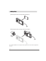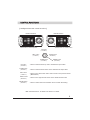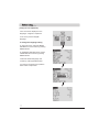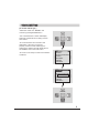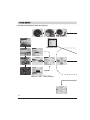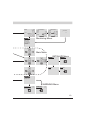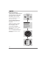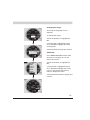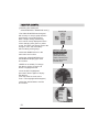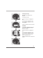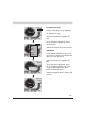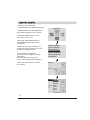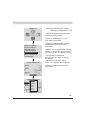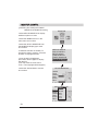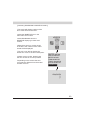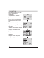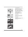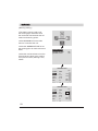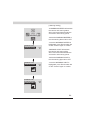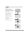
1
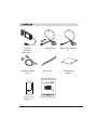
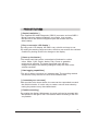
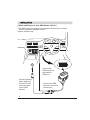
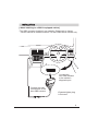
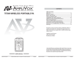
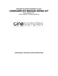
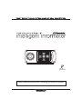
Please read this manual before installing and using this product.
PARTS LIST
Intelligent
Informeter
Main Unit x 1
Cigarette Lighter
Plug x 1
OBD Harness
x1
Zip Ties x 2
TRUST SUPER TUNING SYSTEMS AIMED AT REAL COMPETITORS
Color Insert
Sheet x 9
1
Instruction Manual
x1
NON-OBD Harness
x1
Double-sided
Tape x 2
PRODUCT FEATURES
[ Simple installation ]
•The supplied ISO14230 Diagnostic (OBD II) connector and non-OBD II
Nissan connector makes installation very simple. Just connect
the harness to the vehicleʼs diagnostic port and monitor the ECU
data instantly.
[ Easy to see color LCD display ]
•By using color LCD display, the data is very colorful and easy to see.
•By setting the warning range and color, the driver can monitor the vehicleʼs
condition by looking at the color change on the display.
[ Dress up the interior ]
•The button back light can be customized to illuminate in various
colors. White, Cyan, Purple, Amber, Pink, Green or gradation
mode can be selected. The button back light color will also
change according to the warning settings to notify the driver of the
vehicles condition.
[ Data logging capabilities ]
•This unit is able to record up to 6 selected data. The recording method
can also be set by the user to record more detailed data.
[ Customize your own case ]
•With provided color insert sheets, the case can be customized to match
the vehicleʼs interior. It is also easy to create a one off insert sheet by
tracing the pattern to any decorated sheets.
[ Flexible mounting ]
•By rotating the display 180 degrees, the main unit can be mounted with
the buttons on the right or left. This feature makes mounting of the unit
very flexible.
2
INSTALLATION
[ When installing on an non-OBD Nissan vehicle ]
*The OBD connector location is an example. Please refer to factory
service manual for detailed location.
*Nissan vehicles only.
Connect the
OBD harness to
the vehicleʼs
OBD port.
Use the cigarette
lighter plug and
connect it to the
male connector
on the OBD
harness
3
Connect the OBD
harness to the main
unit harness
INSTALLATION
[ When installing on a OBD II equipped vehicle ]
*The OBD connector location in an example. Please refer to factory
service manual for detailed location. For Non-OBD Nissan vehicle only.
Connect the
Non-OBD harness
to the vehicleʼs
diagnostic port.
Connect the main
unit harness to the
Non-OBD harness.
*Cigarette lighter plug
is not used.
4
INSTALLATION
[ Mounting the main unit using double sided tape ]
[ Mounting the main unit using a cell phone holder ]
•For a detailed installation for the cell phone holder, please refer to the instruction supplied with
the holder.
5
CONTROL FUNCTIONS
[ Intelligent Informeter control functions ]
Reverse Position
*LEFT button in reverse position
Normal Position
UP button
( U button )
LEFT button
( L button )
RIGHT button
( R button )
DOWN button
( D button )
UP button
( U button )
DOWN button
( D button )
LEFT button
( L button )
RIGHT button
( R button )
ENTER button
( E button )
*RIGHT button in normal position
ENTER button
( E button )
•Used to scroll the menu up and to increase the input value.
•Used to scroll the menu down and to decrease the input value.
•Used to move left in each menu and to return to the previous menu.
(Back button)
•Used to move right in each menu and to select Record mode.
•Used to confirm the menu selection and to confirm the setting.
Main Unit Dimensions : H 46mm x W 100mm x T 20mm
6
Before using . . .
[ Setting the unit LANGUAGE ]
•This unit can be displayed in two
languages : English or Japanese.
*This unit is preset to English
language.
To change the language setting
•In the main menu, select the BASIC
SETTING icon and confirm by pushing
ENTER button.
•In the BASIC SETTING menu, select
LANGUAGE and confirm by pushing
ENTER button.
•Select the desired language and
confirm by pushing ENTER button.
•To return to the main menu push the
LEFT button couple times.
7
VEHICLE SETTING
[ To set the vehicle type ]
•Select the center icon “MAKER” and
confirm by pushing ENTER button.
•List of manufacturerʼs names will display.
Select the vehicle this unit is being used on
and confirm.
•The unit will check the connection and
application. If the unit is connected
properly, and the correct vehicle type is
selected, the vehicle type will display above
the “MAKER” icon in the main menu.
•The unit is now ready to monitor the vehicleʼs
conditions.
TOYOTA
NISSAN
NISSAN (NON-OBD)
HONDA
MITUBISHI
SUBARU
DAIHATSU
TOYOTA
NISSAN
NISSAN (NON-OBD)
CONNECTING...
HONDA
MITUBISHI
SUBARU
DAIHATSU
TOYOTA
8
FLOW CHART
[ Use the chart below to check the setting ]
SPEED
PEAK
SPEED
TACHO
SPEED
SPEED
SPEED
D1 VEHICLE
TOYOTA
NISSAN
NISSAN (NON-OBD)
HONDA
MITUBISHI
SUBARU
DAIHATSU
Vehicle List
ALPHARD
IMPREZA
COLOR SETTING
WALLPAPER
METERBOARD
NEEDLE
LOGO
PEAK
BLUE
CONTRAST
16
BACKLIGHT
16
SW LIGHT
WHITE
BUZZER NORMAL
PERCENT REVERSE
COLOR SETTING
DISPLAY DIR
REVERSE
REC MODE
NORMAL
BASIC SETTING Menu
WARNING ZONE
SPEED CONDITION
TACHO
RED
WATER
YELLOW
IGNITION LOW
INJCT
YELLOW
INJC1
RED
9
7000
3500
OFF
OFF
SPEED
6 ROW MONITOR
TRIPLE MONITOR
SPEED
KM/H
TACH
TACH
PEAK
WATER
SPEED
TACH
WATER
IGNIT
INTAK
BATT
DIAGNOSIS
Monitoring Menu
NEEDLE METER
CIRCLE METER
METER & BAR
TWIN MONITOR
TRIPLE MONITOR
6 ROW MONITOR
DIAGNOSIS
MONITOR
Main Menu
INITIALIZE Menu
INITIALIZE
PEAK CLEAR
RESET
PEAK CLEAR
RESET
YES
NO
PEAK CLEAR
RESET
PEAK CLEAR
RESET
YES
NO
WARNING
WARNING ZONE
WARNING BUZZER
WARNING LIGHT
WARNING Menu
WARNING ZONE
WARNING BUZZER
WARNING LIGHT
OFF
ON
OFF
ON
WARNING ZONE
WARNING BUZZER
WARNING LIGHT
OFF
ON
OFF
ON
10
MONITOR
[ Selecting and setting the
NEEDLE METER in MONITOR mode ]
This feature allows our easy to read
analog gauge design to display the
data digitally on the LCD screen.
MONITOR
•Select the MONITOR icon in the
main menu and confirm.
•Select the NEEDLE METER from
the MONITOR display type menu
and confirm.
•SPEED is set initially. To change
the data to monitor, press the E
button to highlight the title.
•Once the title is highlighted,
press the E button again to display
the data list.
(This step must be done with in
5 sec. or the highlight will disappear)
NEEDLE METER
CIRCLE METER
METER & BAR
TWIN MONITOR
TRIPLE MONITOR
6FOLD MONITOR
DIAGNOSIS
PEAK
•Select the desired data to monitor
and confirm.
SPEED
SPEED
SPEED
TACH
WATER
IGNIT
INJCT
INJC1
INJC2
11
PEAK
SPEED
PEAK
Changing the range
The range of the gauge can be
adjusted.
To change the range;
SPEED
SPEED
PEAK
•Press the E button to highlight the
title.
•Once the title is highlighted, press
UP or DOWN to highlight the value
on the gauge.
•Select the desired range and confirm.
SUB DATA
SPEED
GEAR
4WD
EGT-T
EXH-T
NOW
PEAK
BLANK
PEAK
SPEED
In the NEEDLE METER mode, there
are options to display up to 3 sub
data in the corners
•Press the E button to highlight the
title.
•Once the title is highlighted, press
UP or DOWN to highlight one of the
corner in the display and press E
button to display the menu.
•Select the desired data to display and
confirm.
TACH
PEAK
SPEED
SPEED
12
MONITOR (CONTʼD)
[ Selecting and setting the
CIRCLE METER in MONITOR mode ]
•The CIRCLE METER was designed
with an easy to see pie graph with the
smoothness of an analog gauge.
With a simple setting, the warning
zone can be clearly displayed in three
colors changing from green to yellow
to red. The driver can simply monitor the
change in color and drive safely
without staring at the gauge.
•Select the MONITOR icon in the
main menu and confirm.
•Select the CIRCLE METER from
the MONITOR display type menu
and confirm.
MONITOR
NEEDLE METER
CIRCLE METER
METER & BAR
TWIN MONITOR
TRIPLE MONITOR
6FOLD MONITOR
DIAGNOSIS
•SPEED is set initially. To change
the data to monitor, press the E
button to highlight the title.
•Once the title is highlighted,
press the E button again to display
the data list.
(This step must be done with in
5 sec. or the highlight will disappear)
SPEED
•Select the desired data to monitor
and confirm.
PEAK
SPEED
TACH
WATER
IGNIT
INJCT
INJC1
INJC2
13
SPEED
Changing the range
The range of the gauge can be
adjusted.
SPEED
To change the range;
•Press the E button to highlight the
title.
PEAK
•Once the title is highlighted, press
UP or DOWN to highlight the value
on the guage.
•Select the desired range and confirm.
SPEED
In the NEEDLE METER mode, there
are options to display up to 3 sub
data in the corners
PEAK
GEAR
4WD
EGT-T
EXH-T
NOW
PEAK
BLANK
SUB DATA
•Press the E button to highlight the
title.
SPEED
•Once the title is highlighted, press
UP or DOWN to highlight one of the
displays in the corner and press E
button to diplay the menu.
•Select the desired data to display and
confirm.
TACH
WATER
SPEED
PEAK
14
MONITOR (CONTʼD)
[ Selecting and setting the
METER & BAR in MONITOR mode ]
MONITOR
•The METER & BAR setting brings the
race car look & feel in to the cockpit.
This feature will display an analog guage
and a bar type meter.
•Select the MONITOR icon in the
main menu and confirm.
•Select the METER & BAR from
the MONITOR display type menu
and confirm.
•TACH & SPEED is set initially. To
change the data to monitor, press the
E button to highlight the title.
•Once the title is highlighted,
press the E button again to display
the data list.
(This step must be done with in
5 sec. or the highlight will disappear)
•Select the desired data to monitor
and confirm.
NEEDLE METER
CIRCLE METER
METER & BAR
TWIN MONITOR
TRIPLE MONITOR
6FOLD MONITOR
DIAGNOSIS
SPEED
SPEED
SPEED
TACH
SPEED
TACH
WATER
IGNIT
INJCT
INJC1
INJC2
15
SPEED
SPEED
PEAK
SPEED
TACH
Changing the range
Range of the gauge can be adjusted.
To change the range;
•Press the E button to highlight the
title.
GEAR
4WD
EGT-T
TACH
EXH-T
NOW
PEAK
BLANK
SPEED
SPEED
•Once the title is highlighted, press
UP or DOWN to highlight the value
on the gauge.
•Select the desired range and confirm.
SUB DATA
In the NEEDLE METER mode, there
are options to display a 3rd digital sub
data in the top right corner.
SPEED
SPEED
•Press the E button to highlight the
title.
•Once the title is highlighted, press
UP or DOWN to highlight one of the
corner in the display and press E
button to diplay the menu.
•Select the desired data to display and
confirm.
WATER
SPEED
TACH
16
MONITOR (CONTʼD)
[ Selecting and setting the
TWIN MONITOR in MONITOR mode ]
MONITOR
•TWIN MONITOR mode will display 2
large digital readings on the screeen.
•Select the MONITOR icon in the
main menu and confirm.
•Select the TWIN MONITOR from
the MONITOR display type menu
and confirm.
•SPEED & TACH are set initially. To
change the data to monitor, press the
E button to highlight the title.
•Once the title is highlighted,
press the E button again to display
the data list.
(This step must be done with in
5 sec. or the highlight will disappear)
•Select the desired data to monitor
and confirm.
NEEDLE METER
CIRCLE METER
METER & BAR
TWIN MONITOR
TRIPLE MONITOR
6FOLD MONITOR
DIAGNOSIS
SPEED
TACH
SPEED
SPEED
TACH
WATER
IGNIT
TACH
INJCT
INJC1
INJC2
17
[ Selecting and setting the TRIPLE
MONITOR in MONITOR mode ]
MONITOR
•TRIPLE MONITOR mode will display
3 different peices of data.
•Select the MONITOR icon in the
main menu and confirm.
•Select the TRIPLE MONITOR from
the MONITOR display type menu
and confirm.
NEEDLE METER
CIRCLE METER
METER & BAR
TWIN MONITOR
TRIPLE MONITOR
6FOLD MONITOR
DIAGNOSIS
•SPEED, TACH, WATER temp are set
initially. To change the data to monitor,
press the E button to highlight the title.
TRIPLE MONITOR
•Select the desired data to monitor
and confirm.
SPEED
TACH
WATER
•Once the title is highlighted,
press the E button again to display
the data list.
(This step must be done with in
5 sec. or the highlight will disappear)
PEAK
TRIPLE
MONITOR
SPEED
SPEEDTACH
WATER
IGNIT
TACH
INJCT
INJC1
WATER
INJC2
PEAK
18
MONITOR (CONTʼD)
[ Selecting and setting the TRIPLE
MONITOR in MONITOR mode ]
MONITOR
•Select 6FOLD MONITOR to display
6 different peices of data.
•Select the MONITOR icon in the
main menu and confirm.
•Select the 6FOLD MONITOR from
the MONITOR display type menu
and confirm.
•6 different data are set initially. To
change the data to monitor, press the
E button to highlight the title.
•Once the title is highlighted,
press the E button again to display
the data list.
(This step must be done with in
5 sec. or the highlight will disappear)
•Select the desired data to monitor
and confirm.
NEEDLE METER
CIRCLE METER
METER & BAR
TWIN MONITOR
TRIPLE MONITOR
6FOLD MONITOR
DIAGNOSIS
6FOLD MONITOR
SPEED
TACH
WATER
IGNIT
INTAK
BATT
6FOLD
MONITOR
SPEED
TACH
SPEED WATER
TACH IGNIT
WATER
INJCT
IGNIT
INJC1
INTAK
INJC2
BATT
19
[ Selecting DIAGNOSIS in MONITOR mode ]
•This mode will display number of the
error codes stored in the ECU.
•Select the MONITOR icon in the
main menu and confirm.
•Select DIAGNOSIS from the
MONITOR display type menu and
confirm.
MONITOR
•When there are error codes stored
in the ECU, the number of the codes
stored will be displayed.
•This unit is not able to display the
actual error code or the error description.
•If there are any codes, please have
the error check as soon as possible.
•Depending on the vehicle the error
count may be different from the actual
number of errors.
NEEDLE METER
CIRCLE METER
METER & BAR
TWIN MONITOR
TRIPLE MONITOR
6FOLD MONITOR
DIAGNOSIS
DIAGNOSIS
20
BASIC SETTING
Select BASIC SETTING from the main
menu to customize the unit.
[ LANGUAGE ]
•Select ENGLISH or JAPANESE.
[ UNIT ]
•Select km/h for metric units and MPH
for standard units. km/h will display
km/h for speed and C for temp. MPH
will display MPH for speed and F for
temp.
[ CONTRAST, BACKLIGHT ]
•LCDʼs contrast and backlight can be
adjusted by 1~32 steps for best visibility.
[ SW LIGHT ]
•The button back light can be customized
to illuminate in various colors. White,
Cyan, Purple, Amber, Pink, Green
or gradation mode can be selected.
[ BUZZER ]
•The button sound can be turned ON
or OFF.
[ PERCENT ]
The injector duration, airflow meter
voltage, and throttle voltage can
changed to display in percentage.
BASIC SETTING
CONTRAST
BACKLIGHT
SW LIGHT
BUZZER
PERCENT
COLOR SETTING
DISPLAY DIR
REC MODE
16
16
WHITE
REVERSE
NORMAL
CONTRAST
16
WHITE
BACKLIGHT
16
CYAN
SW LIGHT
WHITE
PURPLE
BUZZER AMBER
PERCENTPINK
COLOR SETTING
YELLOW
DISPLAY DIR
GREEN REVERSE
REC MODE
NORMAL
CONTRAST
16
BACKLIGHT
16
SW LIGHT
GRADATION
BUZZER
PERCENT
COLOR SETTING
DISPLAY DIR
REVERSE
REC MODE
NORMAL
21
BASIC SETTING
CONTRAST
BACKLIGHT
SW LIGHT
BUZZER
PERCENT
COLOR SETTING
DISPLAY DIR
REC MODE
16
16
WHITE
REVERSE
NORMAL
COLOR SETTING
WALLPAPER
METER BOARD
NEEDLE
[ COLOR SETTING ]
•The display color can be changed to
black, red, green, yellow, blue,
magenta, cyan, white, darkblue,
light blue, light gray, dark gray, dark
green, and dark amber. In addition
to the 14 colors, a GReddy logo and
3 GReddy cars can also be
selected as wallpaper.
•METER BOARD and NEEDLE
colors can be selected from the
same 14 colors.
[ DISPLAY DIR ]
•Display rotation can be changed
depending on the rotation the unit
being mounted.
[ REC MODE ]
•The Recording cycle can be adjusted
to SMOOTH, STANDARD, or
LONG setting.
LOGO
CONTRAST
16
BACKLIGHT
16
SW LIGHT
GRADIATION
BUZZER NORMAL
PERCENTREVERSE
COLOR SETTING
DISPLAY DIR
REVERSE
REC MODE
NORMAL
22
WARNING
[ Warning setting ]
•This feature can be used to set
the warning light and alarm when
the monitored data exceeds the set
caution and warning points.
WARNING
•Select WARNING from the main
menu to customize the unit.
•Select the WARNING ZONE to set
the warning point for each monitored
items.
•Select the monitored items from the
list and set the yellow zone (caution
zone) and red zone (warning zone)
values.
WARNING ZONE
WARNING BUZZER
WARNING LIGHT
OFF
ON
WARNING ZONE
SPEED
TACH
WATER
IGNIT
INJCT
INJ1
rpm
HIGH
RED
YELLOW
LOW
YELLOW
RED
7000
3500
OFF
OFF
WARNING ZONE
SPEED
TACH
WATER
IGNIT
INJCT
INJ1
23
HIGH
RED
YELLOW
LOW
YELLOW
RED
rpm
7000
3500
OFF
OFF
[ Warning setting ]
•A WARNING BUZZER will activate
the caution and warning alarm
when monitored data exceeds the
set caution and warning points.
WARNING
WARNING ZONE
WARNING BUZZER
WARNING LIGHT
•Select the WARNING BUZZER to
turn the warning alarm ON or OFF.
OFF
ON
•Once the WARNING BUZZER is
highlighted, press E and select ON
or OFF. Press E again to confirm.
•WARNING LIGHT will activate
the caution and warning light
when monitored data exceeds the
set caution and warning points.
•Select the WARNING LIGHT to
turn the warning light ON or OFF.
WARNING ZONE
WARNING BUZZER
WARNING LIGHT
OFF
ON
OFF
ON
WARNING ZONE
WARNING BUZZER
WARNING LIGHT
•Once the WARNING LIGHT is
highlighted, press E and select ON
or OFF. Press E again to confirm.
OFF
ON
OFF
ON
24
INITIALIZE
[ INITIALIZE ]
This feature is used to re set the
unit. The peak memory and the
unit also can be reset. When the unit is
reset, the vehicle setting, basic setting,
and warning points will all be cleared to
the factory settings.
INITIALIZE
•Select INITIALIZE in the main menu.
To clear the peak memory,
•Select PEAK CLEAR in the
INITIALIZE menu and confirm.
PEAK CLEAR
RESET
•Select YES or NO and confirm.
To reset the unit,
•Select RESET in the INITIALIZE
menu and confirm.
•Select YES or NO and confirm.
PEAK CLEAR
RESET
YES
NO
PEAK CLEAR
RESET
YES
NO
25
COLOR INSERT SHEET
[ How to install the color insert sheet ]
•Remove the clear cover by removing the four small screws with a small flat head
screw driver as show in the illustration below.
•Match the screw holes of the color insert sheet with the clear cover and trace the
edge with a sharp pencil.
•Cut the color sheet out by cutting along the traced line with a scissors or cutter.
•Place the cut color sheet between the main unit and the clear cover.
•Secure the clear cover and color insert sheet with the four small screws.
Main unit
Color insert sheet
Small cover screws
Clear cover
Caution
•When using scissors or cutter, please be careful not to cut your self.
26