1
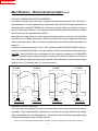
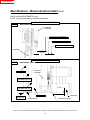
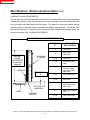
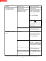
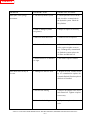
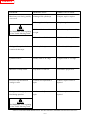
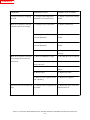
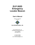
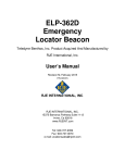
CONTENTS
MANITOU NORTH AMERICA, INC.
6401 IMPERIAL DRIVE
Waco, TX 76712--6803
NOTE: This Operator/Service Manual contains “general” instructions for mast
maintenance and repair. It must be used in conjunction with the parts illustrations
found in your Mast Parts Manual. Updates of the Mast Parts Manual are made
periodically, revising components and Models as released for production. If your Mast
Model or parts are not found in the Parts Manual, please contact the Manitou North
America Parts Department for the latest information available.
MAST
OPERATOR/SERVICE
MANUAL
For Parts Orders contact your Manitou North America Dealer or call:
Manitou North America, Parts Dept. 800--425--3727 or (254) 799--0232
Parts Dept. Fax: (254) 867--6504
Website: www.manitou--na.com
CATALOG B418
R10--05
CONTENTS
CONTENTS
CONTENTS
SAFETY PRECAUTIONS
3
MAST COMPONENTS
4
MAST INSTALLATION, OPERATION & MAINTENANCE
5
INSTALLATION
OPERATION
MAINTENANCE
LUBRICATION SCHEDULE
CHAIN INSPECTION
CHAIN ADJUSTMENTS
MAST ROLLERS
CARRIAGE SIDE--PLAY OR THRUST ROLLERS
5
5
6
6
6
7
7
7
MAST REMOVAL, REPAIR AND ADJUSTMENT
8
PREPARATION
MAST REMOVAL AND DISASSEMBLY
ROLLER ADJUSTMENTS
CARRIAGE THRUST ROLLERS
RAIL CHAINS ADJUSTMENTS
CARRIAGE CHAINS ADJUSTMENTS
PRIMARY/SECONDARY CYLINDER(S) DISASSEMBLY
PRIMARY/SECONDARY CYLINDER(S) RE--ASSEMBLY
TROUBLE SHOOTING GUIDE
8
8
9
9
10
12
13
13
14
NOTICE! STUDY THE ENTIRE REPAIR MANUAL BEFORE OPERATING, REPAIRING OR ADJUSTING THE MAST!
-- 1 --
CONTENTS
NOTES:
NOTICE! STUDY THE ENTIRE REPAIR MANUAL BEFORE OPERATING, REPAIRING OR ADJUSTING THE MAST!
-- 2 --
CONTENTS
SAFETY PRECAUTIONS
IMPORTANT: BEFORE YOU OPERATE THE MAST, MAKE SURE YOU HAVE READ
AND FULLY UNDERSTAND THE MANUFACTURER’S MANUALS FOR YOUR FORKLIFT. IF THE MANUALS ARE MISSING, GET A REPLACEMENT MANUAL FROM YOUR
EMPLOYER, DEALER OR FORKLIFT MANUFACTURER.
KEEP SAFETY MANUALS ON THE FORKLIFT AT ALL TIMES.
SAFETY IS YOUR RESPONSIBILITY!
-- ONLY YOU CAN PREVENT SERIOUS INJURY OR DEATH FROM UNSAFE PRACTICES!
PRACTICE ALL USUAL AND CUSTOMARY SAFE WORKING PRECAUTIONS, INCLUDING THE FOLLOWING:
1. NEVER CARRY PASSENGERS ON THE MAST OR FORKS!
2. Never use the mast or forks as battering rams.
3. Make daily inspections of the mast’s performance, components, hydraulics and hose connections.
4. Avoid entanglement hazard, keep yourself and others away from the mast’s moving parts.
5. DO NOT climb on the mast.
6. If the mast does not operate properly, have it inspected and repaired immediately.
7. Do not operate the Mast without a legible load chart (do not over--load the mast).
8. Replace forks (in pairs) that are cracked or damaged, NEVER use forks repaired by welding.
9. Check that the forks are secure (unable to change position while carrying loads).
10. Plan ahead, know how and where you will travel, turn and pickup, lift and place loads.
11. Use a signal person when placing high loads.
12. Operate the mast smoothly (raising, lowering, and tilting of mast and forks), do not allow the lift
cylinders to hit the end of their stroke abruptly.
13. Lower the forks to the ground when the Forklift is not in use.
NOTICE! STUDY THE ENTIRE REPAIR MANUAL BEFORE OPERATING, REPAIRING OR ADJUSTING THE MAST!
-- 3 --
CONTENTS
MAST COMPONENTS
K--D MANITOU Masts are designed primarily for use on Industrial Fork Lift Trucks. Each Mast
Series is rated based on lifting capacity and lifting height. The Mast’s lifting capacity also varies
depending on the Lift Truck and its application. Load capacities are determined at 24” load centers,
centered on the mast and must include any attachments on the carriage. The Lift Truck Identification Plate shows the mast’s model, attachments and maximum lifting capacities based on that particular truck and mast combination.
The mast’s structural rails are manufactured from SAE1027 steel beams, rolling one within the other
on steel rollers. The rails are engineered to distribute thrust loads evenly between the rollers and
rail. All mast components are designed to work as a unit, providing maximum strength and endurance for the rated load.
The most common method of handling loads is with the use of forks. Masts with ITA (Industrial Truck
Association) carriages will also handle additional attachments (contact your dealer).
The mast lift is powered by hydraulics, supplied by the forklift at the control valve. The mast is lowered using the control valve and gravity, internal valves keep the mast from lowering too quickly.
The Figures below show the general principles of mast lifting sequences:
Fig. 1) The mast is lowered or collapsed.
Fig. 2) The lift lever on the forklift is activated, causing hydraulic fluid to enter the primary cylinder.
The cylinder rises, pushing the primary chain upward, raising the carriage. This first stage of carriage lift is called ”free lift”, it is the distance of lift available without increasing the mast’s height.
Fig. 3) As the secondary cylinders are activated, the inner rail and secondary rail (connected by
chains) rise progressively. The upward lift continues until the secondary cylinders are fully extended. The carriage is lowered in reverse sequence (by gravity) as hydraulic oil is removed from
the lift cylinders. These principles apply to 4 and 5 stage masts as well, utilizing additional rails, lift
cylinders and chains.
SECONDARY CHAIN
PRIMARY CHAIN
PRIMARY CYLINDER
(LOWERED)
CARRIAGE
INNER RAIL
FORKS
Fig. 1
INTERMEDIATE
RAIL
Fig. 3
OUTER
RAIL
PRIMARY CYLINDER
(EXTENDED)
Fig. 2
SECONDARY
CYLINDER
(EXTENDED)
NOTICE! STUDY THE ENTIRE REPAIR MANUAL BEFORE OPERATING, REPAIRING OR ADJUSTING THE MAST!
-- 4 --
CONTENTS
MAST INSTALLATION, OPERATION & MAINTENANCE
INSTALLATION
1.) Before installing the new mast, have an experienced mast mechanic inspect it carefully. Check
for any damages, missing or loose components that may have occurred during shipping. Contact
your dealer immediately if there are any questions concerning the mast’s condition.
2.) Before performing any welding on the mast, contact K--D Manitou for approval. K--D Manitou
is not responsible for unapproved field welding, attachments or mountings designed by other
manufacturers.
3.) Mount the mast to the lift truck, using a overhead hoist and frame rated to at least 3 tons.
Make sure the flow control valve (fuse) is correctly installed. Connect the tilt cylinders and hydraulic
hose(s). Insure the hydraulic tank is filled with hydraulic oil.
CAUTION! OBSERVE ALL SAFETY PRECAUTIONS WHEN WORKING WITH OR ON THE MAST!
NEVER place any part of one’s body into the working zone of the mast while it is moving or extended.
Never work on the mast while it is loaded; remove the load first! If work must be performed on an extended mast, block and chain the rail assemblies and carriage to prevent mast collapse.
OPERATION (INITIAL)
Before the mast is placed into service, perform the following procedures:
1.) Attach the forks (or approved attachment) to the mast carriage.
2.) Without a load on the forks, extend and retract the mast through one complete cycle.
3.) With the mast fully lowered, check the lift truck’s hydraulic tank and add fluid if necessary.
4.) Extend and retract the mast four more times. This action will force air in the system to the top
of the lift cylinders where the bleed screws are located.
5.) Raise the forks to about ten inches off the ground.
WARNING! STAY CLEAR OF THE CARRIAGE AND FORKS
AS THEY ARE LOWERED DURING CYLINDER BLEEDING!
CAUTION! WEAR PROPER EYE PROTECTION WHEN BLEEDING THE HYDRAULIC CYLINDERS!
6.) Each cylinder must be bled, one at a time, any sequence. Open the bleed screw no more than
one turn. The weight of the carriage will force any air and hydraulic oil out of the cylinder through
the bleed hole. If the carriage reaches the bottom of its travel before all the air is bled, close the
bleed screw and repeat steps 5 and 6.
7.) When the oil stream no longer contains air bubbles, close the bleed screw.
8.) Check the lift truck’s hydraulic tank and add fluid if necessary.
9.) Extend and retract the mast again, if the mast doesn’t operate smoothly or if it appears to be
”spongy”, repeat steps 2 through 9.
10.) Test the mast with a light load (if any problems occur at this point, see chapter TROUBLE
SHOOTING GUIDE). If operating smoothly, test the mast with 1/2 its rated load capacity, and then
its full rated load capacity. If the mast continues to operate smoothly, it is ready to place into service.
NOTICE! STUDY THE ENTIRE REPAIR MANUAL BEFORE OPERATING, REPAIRING OR ADJUSTING THE MAST!
-- 5 --
CONTENTS
MAST INSTALLATION, OPERATION & MAINTENANCE (cont.)
MAINTENANCE
Some flaking of material can be expected where the carriage rollers contact the inner rail. After a
few hundred hours of operation this flaking should subside. Keep these flakes of material removed
by cleaning the rails with a wire brush (WEAR PROPER EYE PROTECTION AND GLOVES!). Also,
note the following cleaning/lubrication schedule . . .
CLEANING/LUBRICATION SCHEDULE:
1.) Every 200 Hours or monthly: Lightly oil each chain with a brush, using SAE 30 Non--Detergent oil.
2.) Every 500 Hours: Using a steel wire brush, clean and remove any scaling or debris along all roller
contact points on the rails. Keep the rollers and rails clean from debris.
3.) Every 1,000 Hours: Clean the chains with solvent, blow dry with air and re--oil.
CHAIN INSPECTION:
Inspect lift chains daily, before operating the truck. Look for cracked, broken or missing link plates,
bent, protruding or seized pins, and evidence of rust or corrosion. When locating this type of damage, the chains must be replaced. Ensure tension on the chain pairs are equal. Verify that all cotter
pins and lock nuts are in place. Verify that all chains are clear from side contact with headers and
carriage. Make sure snap rings are in the proper place on chain sheave shafts. Do not operate the
mast if any of these problems exist.
The mast chains begin to wear and stretch in length as they are used. A simple measurement of the
chain’s pitch over a given length will determine its status for replacement. First determine the pitch
of your chain by measuring the distance ”X” between two chain pins as shown below.
NOTE: The chain pitch will be either 5/8”, 3/4”, or 1”.
A 5/8” pitch chain must be replaced if it measures 10 1/4” or more across 16 pitches or spaces.
A 3/4” pitch chain must be replaced if it measures 12 3/8” or more across 16 pitches or spaces.
A 1” pitch chain must be replaced if it measures 24 3/4” or more across 24 pitches or spaces.
CHAIN PITCH
ONE PITCH
”X”
CHAIN PINS
THE CHAIN TYPE SHOWN IS FOR REFERENCE ONLY.
CHAIN TYPES VARY DEPENDING ON THE MAST MODEL
NOTICE! STUDY THE ENTIRE REPAIR MANUAL BEFORE OPERATING, REPAIRING OR ADJUSTING THE MAST!
-- 6 --
CONTENTS
MAST INSTALLATION, OPERATION & MAINTENANCE (cont.)
CHAIN ADJUSTMENTS:
The chains should be adjusted with the mast in a vertical position, the carriage completely lowered
and unloaded. Facing the front of the mast, adjust the chains in pairs, beginning with the rear pair.
Provide equal tension on the chains. A critical measurement during chain adjustment is the mast
rails alignment to the outer rail, see RAIL CHAINS ADJUSTMENT. Also critical is the carriage
chains adjustments. When the carriage chain(s) are properly adjusted, the lower carriage rollers
will protrude below the inner rail. The distance that the carriage rollers protrude varies between
Mast Models! See CARRIAGE CHAINS ADJUSTMENTS.
MAST ROLLERS:
All mast rail rollers, carriage rollers, chain sheaves and cylinder head guide rollers (where applicable) are sealed for life and require no additional lubrication. Bearing life of the rollers varies depending on application and conditions of operation. Should the mast show signs of lateral wear or excessive side play within the rail sections, the mast will require ”shimming” (see RAIL ROLLER SHIMS
below) and/or replacement of the rollers. If not properly shimmed, the rail rollers can distroy the stub
shafts on which they ride (replacing stub shafts requires welding by an authorized welder at an approved dealership; contact K--D Manitou). See RAIL and CARRIAGE ROLLER ADJUSTMENTS
on page 9.
CARRIAGE SIDE--PLAY OR THRUST ROLLERS:
The carriage thrust rollers keep the carriage centered and in contact with the inner rails, providing
smooth load handling. The thrust rollers are adjustable by use of eccentric shafts and shims (see
your Mast Parts Book for assembly). They should be checked frequently and adjusted when necessary.
RAIL ROLLER SHIMS:
The following diagram identifies Rail Roller Shims by dimensions and part no.. Use the information
to verify the shims required for proper clearance between rollers and rails as described on page 9.
SHIM PART NO.:
R22 = 0.015 THK
R426 = 0.060 THK
2 3/8”
RAIL ROLLER SHIMS
2”
SHIM PART NO.:
R206 = 0.015 THK
R427 = 0.060 THK
1 13/32”
1 25/32”
NOTICE! STUDY THE ENTIRE REPAIR MANUAL BEFORE OPERATING, REPAIRING OR ADJUSTING THE MAST!
-- 7 --
CONTENTS
MAST REMOVAL, REPAIR AND ADJUSTMENT
PREPARATION:
1.) The work site must be clean, have a concrete floor, and an overhead hoist and frame rated
to at least 3 tons. Follow all safety instructions regarding the use of hand and power tools.
2.) Steam clean the mast thoroughly, removing all dirt, debris and grease.
CAUTION! OBSERVE ALL SAFETY PRECAUTIONS WHILE OPERATING THE
HOIST AND DISMANTLING THE MAST!
MAST REMOVAL AND DISASSEMBLY:
Make notes during disassembly, referring to your Mast Parts Book for component descriptions and
diagrams. Important: record the roller clearances and chain adjustments before removing the
carriage or rails, see the following pages.
1.) Remove the load backrest (if installed) and forks.
2.) Disconnect the hydraulic hose(s), allowing the mast to drain. Clean any spilt oil immediately.
3.) Attach a properly rated hoist belt to the mast, lift the mast slightly.
4.) Disconnect the mast side shift cylinder (if installed) and tilt cylinders from the mast.
5.) Disconnect the mast from the lift truck. WARNING: The mast may swing from the lift truck,
be cautious!
6.) Lay mast horizontally, carriage side facing up. Use blocks to level the mast on the floor.
7.) Remove, clean and inspect the carriage chain(s), see CHAIN INSPECTION.
8.) Dismantle, clean and inspect the crosshead assembly. Replace any worn or damaged parts.
9.) Using the hoist for support, roll the carriage out of the lower end of the mast.
10.) Dismantle, clean and inspect all of the carriage rollers. Note placement of all roller shims.
Re--place any worn or damaged parts. See ROLLER ADJUSTMENTS before beginning
mast assembly.
11.) Remove the tubes, hoses, hose sheaves, and chain sheaves (as they become accessible).
Clean and inspect the components, replacing any that are worn or damaged.
12.) Remove the primary cylinder assembly. See PRIMARY CYLINDER DISASSEMBLY.
13.) Remove, clean and inspect remaining chains, see CHAIN INSPECTION.
14.) Fully extend the inner rail and, using the hoist, lift the inner rail through the cut--out of the
intermediate rail. Remove, clean and inspect the rollers and shims, replace any worn or
damaged parts. Note placement of the roller shims.
15.) Remove secondary cylinder assemblies (as they become accessible). See SECONDARY
CYLINDER DISASSEMBLY.
16.) Remove the remaining rails (as they become accessible), refer to instruction #14.
17.) Re--assemble the mast in reverse order as disassembled, using your notes as necessary.
See ROLLER ADJUSTMENTS before beginning mast assembly.
18.) Before returning the mast to service, see MAST INSTALLATION, OPERATION &
MAINTENANCE.
NOTICE! STUDY THE ENTIRE REPAIR MANUAL BEFORE OPERATING, REPAIRING OR ADJUSTING THE MAST!
-- 8 --
CONTENTS
MAST REMOVAL, REPAIR AND ADJUSTMENT (cont.)
RAIL AND CARRIAGE ROLLER ADJUSTMENTS:
If excessive side play of the mast rails or carriage is observed during operation, the rail rollers require adjustment. For roller adjustment the mast must be removed from the lift truck and placed in a
horizontal position (see MAST REMOVAL, on the previous page). Before removing the carriage or
rails, record the roller clearances. The clearance is measured at the point where the roller is nearest
the rail’s web (see the applicable figure below).
Begin with the carriage rollers, move the carriage to its highest position on the inner rail. Check both
top rollers first, recording the clearances. Record the center rollers (where applicable) and bottom
rollers in the same manner. Also, record the roller clearances of each mast rail assembly before it is
removed.
Clearance is adjusted using shims .015” to .060” thickness (see RAIL ROLLER SHIMS on page 7),
placed on stub shafts at assembly. The roller must be removed to reveal the stub shaft and shims.
(NOTICE: If the stub shaft is worn or damaged it must be replaced, contact your K--D MANITOU
Dealer.) The rollers must be shimmed evenly, using the same number and thickness of shims on
either side of the rail, keeping the rail properly centered. When adjusted correctly, the rails should be
snug but free to roll manually while in a horizontal position.
“J” RAIL
“C” RAIL
“I” RAIL
“I” RAIL
ROLLER
ROLLER
WEB
WEB
WEB
FLANGE
FLANGE
.015”
FIGURE ’A’
.015”
.015”
FIGURE ’B’
FIGURE ’C’
.015”
FIGURE ’D’
CARRIAGE THRUST ROLLERS:
The thrust rollers are adjustable by use of an eccentric shaft or shims (see your Mast Parts Book for
assembly). These rollers should be adjusted so as to center the carriage within the rail, making
slight contact with the inner rail during operation. Inspect these rollers frequently, making adjustments
as required to maintain smooth carriage operation.
NOTICE! STUDY THE ENTIRE REPAIR MANUAL BEFORE OPERATING, REPAIRING OR ADJUSTING THE MAST!
-- 9 --
CONTENTS
MAST REMOVAL, REPAIR AND ADJUSTMENT (cont.)
RAIL CHAINS ADJUSTMENTS:
Important: adjust the rail chains before the carriage chains. The chains should be adjusted with the
mast in a vertical position, the carriage completely lowered and unloaded. Facing the front of the
mast, adjust the chains in pairs, beginning with the rear pair. Provide equal tension on the chains.
The rail chains of most Mast Models are adjusted aligning the mast rails evenly (see figure 1).
Exceptions are the Mast Models 1400’s, 4700’s, 4800’s, and 5300’s. It is critical that the masts be
adjusted according to the appropriate figure below or on the following page.
ALL FIGURES VIEWED FROM LEFT SIDE OF MAST
FIG. 1
MOST MAST MODELS
HYDRAULIC
CYLINDER
TYPICAL MAST RAIL ALIGNMENT
(CRITICAL: Note the exceptions
listed above!)
See:
CARRIAGE
CHAINS
ADJUSTMENTS
CARRIAGE
CARRIAGE
ROLLER
FORKS
FIG. 2
MAST MODEL 4700’s
FIG. 3
HYDRAULIC
CYLINDER
MAST MODEL 4800’s
4”
4”
BOTTOM OF
OUTER RAIL
TOP OF INNER RAIL
5 3/4”
TOP OF CENTER RAIL
BOTTOM OF
INNER RAIL
TOP OF OUTER RAIL
CARRIAGE
NOTICE! STUDY THE ENTIRE REPAIR MANUAL BEFORE OPERATING, REPAIRING OR ADJUSTING THE MAST!
-- 10 --
CONTENTS
MAST REMOVAL, REPAIR AND ADJUSTMENT (cont.)
RAIL CHAINS ADJUSTMENTS (cont.):
NOTE: See previous page for important information.
MAST VIEWED FROM LEFT SIDE
FIG. 4
MAST MODEL 5300’s
HYDRAULIC
CYLINDER
BOTTOM OF OUTER RAIL
BOTTOM OF CENTER RAIL
BOTTOM OF INNER RAIL
CARRIAGE
2 13/16”
MAST VIEWED FROM FRONT SIDE
FIG. 5
MAST MODEL 1400’s
HYDRAULIC
CYLINDER
OUTER RAIL
OUTER
INTERMEDIATE RAIL
INNER
INTERMEDIATE RAIL
BOTTOM OF
OUTER RAIL
1 3/8”
INNER RAIL
RAIL ROLLERS
CARRIAGE
CARRIAGE ROLLER
NOTICE! STUDY THE ENTIRE REPAIR MANUAL BEFORE OPERATING, REPAIRING OR ADJUSTING THE MAST!
-- 11 --
CONTENTS
MAST REMOVAL, REPAIR AND ADJUSTMENT (cont.)
CARRIAGE CHAINS ADJUSTMENTS:
The carriage chains should be adjusted with the mast in a vertical position, the carriage completely
lowered and unloaded. When properly adjusted, the lower carriage rollers will protrude below the
inner rail slightly, with equal tension on both chains. The distance or dimension that the carriage
rollers protrude is critical and must be maintained for optimum mast operation. Consult the chart
below for the dimension “A” required for your mast model. Before adjusting the carriage chains, see
the previous pages; RAIL CHAINS ADJUSTMENTS.
CARRIAGE CHAIN ADJUSTMENT CHART
DIMENSION
”A”
IMPORTANT:
See RAIL
CHAINS
ADJUSTMENTS
for mast rails
alignment
CARRIAGE
HYDRAULIC
CYLINDER
DIMENSION
”A”
0”
TFL & DCV
1”
3500, 3600,
4300, 5300
1 1/8”
1300, 7700
1 1/4”
2100, 2300, 2400,
7000
1 3/8”
1100, 1400,
1400ER, 1400M,
4000, 7500, 7600,
9300, 9400
1 1/2”
4700, 4900, 6900
1 5/8”
8000, 9000
1 3/4”
1700, 4100, 4200,
4400, 4500, 5700,
5800, 7900
BOTTOM OF
INNER RAIL
FORKS
2”
CARRIAGE
ROLLER
APPLICABLE
MAST MODELS
2 1/8”
4800, 5500, 5500ER,
6400
1000, 1200, 7300
NOTICE! STUDY THE ENTIRE REPAIR MANUAL BEFORE OPERATING, REPAIRING OR ADJUSTING THE MAST!
-- 12 --
CONTENTS
MAST REMOVAL, REPAIR AND ADJUSTMENT (cont.)
PRIMARY/SECONDARY CYLINDER(S) DISASSEMBLY:
Make notes during disassembly, also refer to your Mast Parts Book for component descriptions and
diagrams.
1. Secure the Primary/Secondary Cylinder in a suitable vise (remove any hose fittings and fuses).
2. Using a chain wrench, rotate the base plug until the pointed end of the lock wire appears in the
base plug slot. Place a screwdriver under the end of the lock wire. Rotate the base plug toward the
screwdriver to extract the lockwire.
3. Carefully drive or push on the piston rod to remove the base plug from the bottom of the cylinder.
(Take care not to drop any fuse held in the adapter fitting found on some Secondary Cylinders.)
NOTE: ”O” ring(s) and back--up ring(s) must be replaced if the base plug is removed.
4. Carefully drive the piston through the bottom of the barrel.
5. All seals, wear rings and other cylinder internal parts are now accessible. These parts should be
removed and worn or damaged parts discarded.
6. Thoroughly clean and dry all remaining parts.
7. Thoroughly inspect all parts for nicks, scratches or other damage.
NOTE: Replace the wear rings only if they are damaged or excessively worn.
PRIMARY/SECONDARY CYLINDER(S) RE--ASSEMBLY:
Lubricate all internal components (wear rings, seals, etc.) with clean hydraulic fluid during assembly.
1. Install both wear rings into the top of the barrel and one onto the bottom of the piston (where
applicable).
2. Install the cylinder seal into the barrel, grooved side facing bottom of barrel (where applicable).
3. Install the wiper seal into the barrel.
4. Carefully install the piston into the barrel, allow the piston to protrude from the top end of the
barrel approximately four inches.
NOTE: Reinstall fittings using a thread sealant such as Pipe Dope, Locktite, etc. Do not use teflon
tape, it may be released into the hydraulic system.
5. Ensure the fuse is properly installed in the base plug (where applicable).
6. Install the back--up ring, then the ”O” ring onto the top groove of the base plug.
7. Carefully install the greased base plug into the barrel.
8. Rotate the base plug until the hole in the plug aligns with the slot in the barrel. Insert the hook
end of the lock wire into the base plug hole. Continue to rotate the base plug, pulling the lockwire
completely into the barrel. (Re--install hose fittings and fuses where applicable.)
9. Collapse the cylinder to prevent damage to the chrome piston surface until installation into Mast.
NOTICE! STUDY THE ENTIRE REPAIR MANUAL BEFORE OPERATING, REPAIRING OR ADJUSTING THE MAST!
-- 13 --
CONTENTS
TROUBLE SHOOTING GUIDE
The Trouble Shooting Guide found on the following pages addresses problems sometimes
encountered during mast operations. It also lists the probable causes and recommended
corrective actions to restore the mast to its proper operating condition. Before repairing a
faulty mast, read all safety precautions!
WARNING:
1. IF A MAST RAIL OR CARRIAGE BECOMES JAMMED OR HUNG--UP; REMOVE
THE MAST FROM SERVICE, MAKING NECESSARY REPAIRS IMMEDIATELY!
2. USE ONLY THE APPROPRIATE TOOLS AND APPROVED HOIST/HARNESS
DURING MAST REPAIR OR ADJUSTMENTS!
3. NEVER PLACE ANY PART OF YOUR BODY INSIDE THE WORKING AREA OF A
JAMMED MAST!
4. DO NOT OPERATE THE MAST WITH A DAMAGED HYDRAULIC SYSTEM.
NOTICE! STUDY THE ENTIRE REPAIR MANUAL BEFORE OPERATING, REPAIRING OR ADJUSTING THE MAST!
-- 14 --
CONTENTS
PROBLEM:
PROBLEM CAUSE:
CORRECTIVE ACTIONS:
Mast will not lift load or
lift cylinder does not move.
1. Mast overloaded.
1. Reduce the load.
2. Insufficient or no oil flow
supplied to the cylinder.
2. Check the truck’s hydraulic
system: low oil level, defective
pump, damaged control valve or
leaks in the supply line.
Make repairs as required.
NOTE: Anytime oil is added
to the hydraulic tank, check the
lift cylinders for air, they may
need to be bled.
Lifts load slowly or to partial
height.
3. Relief valve setting too low.
3. Adjust relief valve, do not
exceed recommended setting.
1. Low on oil.
1. Check the truck’s hydraulic
system: low oil level, defective
pump, damaged control valve or
leaks in the supply line.
Make repairs as required.
2. Mast cylinder seal failure.
2. Replace the seals. Failure
caused by oil contamination requires the system be flushed, filters
be replaced and fresh oil installed.
3. Relief setting too low.
3. Adjust relief valve, do not
exceed recommended setting.
4. Mast rollers shimmed too tight, 4. Check rollers and rail alignrails are off center or not lubricated, ment. Repair, adjust or lubricate
as necessary.
defective rollers.
NOTICE! STUDY THE ENTIRE REPAIR MANUAL BEFORE OPERATING, REPAIRING OR ADJUSTING THE MAST!
-- 15 --
CONTENTS
PROBLEM:
PROBLEM CAUSE:
CORRECTIVE ACTIONS:
Mast jerks or has spongy
movement.
1. Air in the hydraulic system.
1. Check hydraulic oil level in the
tank, check for vacuum leaks in
the hydraulic system. Bleed the
lift cylinders.
2. Bent or damaged cylinder
rod (piston).
2. Repair or replace as necessary.
3. Mast rails need lubrication.
3. Lubricate rails as required.
4. Defective relief valve.
4. Remove and inspect the relief
valve, repair or replace as necessary. If damaged by contaminated
oil; flush the system, replace the
oil filters and add fresh oil.
5. Rollers defective or shimmed
too tight.
5. Re--shim or repair as needed.
1. Damaged or defective seals.
1. Replace the seals. Failure caused
by oil contamination requires the
system be flushed, filters be replaced
and fresh oil installed.
2. Pressure line leaking.
2. Inspect all hydraulic lines, hoses
and connections. Tighten or replace
as necessary.
3. Control valve leaking.
3. Repair or replace the control
valve.
Mast drifts down slowly on
its own.
NOTICE! STUDY THE ENTIRE REPAIR MANUAL BEFORE OPERATING, REPAIRING OR ADJUSTING THE MAST!
-- 16 --
CONTENTS
PROBLEM:
PROBLEM CAUSE:
CORRECTIVE ACTIONS:
Mast lowers too slowly, partially
or not at all.
1. Damaged lift cylinders(s).
1. Inspect, repair or replace.
2. Flow regulator faulty.
2. Replace regulator.
3. Rollers defective or shimmed
too tight.
3. Re--shim or repair as needed.
4. Mast rails need lubrication.
4. Lubricate rails as required.
Carriage drifts up when load
is removed, then stops.
1. Air in cylinder(s).
1. Bleed the cylinder(s).
Cylinders leak oil.
1. Faulty seals or “O” rings.
1. Replace seals or “O” rings.
Mast does not fully extend.
1. Hydraulic oil tank low.
1. Fill tank to proper level.
Excessive side movement in
carriage or rails.
1. Rollers need adjustment or
repair.
1. Shim or replace rollers as
required.
Carriage or rails hang--up or
bind during operation.
1. Rollers need adjustment or
repair.
1. Shim or replace rollers as
required.
NOTICE!
See WARNING at the beginning
of the Trouble Shooting Guide.
NOTICE!
See WARNING at the beginning
of the Trouble Shooting Guide.
NOTICE! STUDY THE ENTIRE REPAIR MANUAL BEFORE OPERATING, REPAIRING OR ADJUSTING THE MAST!
-- 17 --
CONTENTS
PROBLEM:
PROBLEM CAUSE:
CORRECTIVE ACTIONS:
Carriage is hitting or scrapping
the rails.
1. Carriage rollers improperly
shimmed or worn excessively.
1. Adjust or replace the carriage
rollers.
Mast out of sequence on ascent,
rails move before the carriage.
1. Carriage travel is obstructed.
1. Remove obstruction.
2. Carriage thrust rollers damaged
or need adjustment.
2. Adjust or replace the thrust
rollers.
3. Carriage rail rollers damaged
or need adjustment.
3. Adjust or replace the rail
rollers.
4. Load excessively off center.
4. Center the load on the
carriage.
1. Rails are shimmed too tight.
1. Re--shim the rails as required.
2. Center rail shimmed too tight
in the outer rail.
2. Re--shim the rail as required.
3. Obstruction or debris.
3. Remove any obstructions or
debris.
4. Broken roller.
4. Replace the roller.
5. Defective flow regulator in the
lift cylinder(s).
5. Replace the regulator.
1. Carriage roller on opposite side
is broken.
1. Replace the roller, clean and
lubricate the rail.
Mast out of sequence on decent,
the carriage lowers before the
rails retract.
Excessive wear on one inner rail
only.
NOTICE! STUDY THE ENTIRE REPAIR MANUAL BEFORE OPERATING, REPAIRING OR ADJUSTING THE MAST!
-- 18 --
CONTENTS
NOTES:
NOTICE! STUDY THE ENTIRE REPAIR MANUAL BEFORE OPERATING, REPAIRING OR ADJUSTING THE MAST!
-- 19 --
CONTENTS
NOTES:
NOTICE! STUDY THE ENTIRE REPAIR MANUAL BEFORE OPERATING, REPAIRING OR ADJUSTING THE MAST!
-- 20 --