1
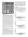
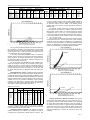
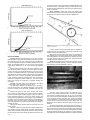
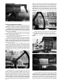
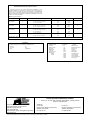
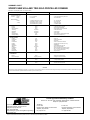
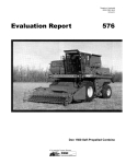
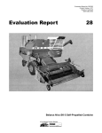
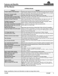
Printed: May, 1984
Tested at: Humboldt
ISSN 0383-3445
Group 4c
EVALUATION REPORT
364
SPERRY NEW HOLLAND TR85 SELF-PROPELLED COMBINE
A Co-operative Program Between
ALBERTA
FARM
MACHINERY
RESEARCH
CENTRE
PAMI
PRAIRIE AGRICULTURAL MACHINERY INSTITUTE
SPERRY NEW HOLLAND TR85 SELF-PROPELLED
COMBINE
MANUFACTURER:
Sperry New Holland
Division of Sperry Rand Corporation
New Holland, Pennsylvania 17557
RETAIL PRICE:
$123,300 (May, 1984, f.o.b. Humboldt, with a 13 ft (4.0 m) header,
10 ft (3.0 m) Victory pickup, variable spewed feeder, feeder jack
stand, high speed rotor kit, straw spreaders, 28L x 26 R1 drive
tires, 11 x 16 F2 steering tires, grain loss monitor, starting uid
injector kit, block heater, radio, cab heater, windshield wiper, and
service oodlight).
DISTRIBUTORS:
Sperry New Holland
P.O. Box 777
Winnipeg, Manitoba R3C 2L4
Sperry New Holland
P.O. Box 1907
Regina, Saskatchewan S4N 2S3
Sperry New Holland
P.O. Box 1616
Calgary, Alberta T2P 2M7
FIGURE 1. Sperry New Holland TR85: (1) Rotors, (2) Threshing Concave, (3) Separating
Concave, (4) Discharge Beater, (5) Beater Grate, (6) Cleaning Shoe, (7) Stone Ejection
Roller, (8) Tailings Return.
SUMMARY AND CONCLUSIONS
Capacity: In the capacity tests, the MOG Feedrate* at 3% total
grain loss was 450 and 650 lb/min (12.3 and 17.7 t/h) in Bonanza
barley. In wheat, at power limit, total loss reached only 1.2% of
yield in Columbus and 2.0% in Neepawa. The MOG Feedrates
at these loss levels were 560 lb/min (15.3 t/h) in Neepawa and
590 lb/min (16.1 t/h) in Columbus.
In barley crops at 3% total grain loss, the Sperry New Holland
TR85 had approximately 2 times the capacity of the Machinery
Institute reference combine. In wheat, the maximum feedrates
achieved by the Sperry New Holland TR85, at less than 2% total
grain loss, were about 1.4 to 1.7 times those of the reference
combine at 3% total grain loss.
Quality of Work: Pickup performance was good in all crops. It
picked cleanly at speeds up to 6 mph (9.6 km/h) and fed the crop
evenly under the table auger. Feeding was good for most crops,
however, the table auger plugged frequently in bunchy windrows.
The feeder backfed occasionally in rye crops especially at the
lower feeder speeds. Optimum rotor feeding occurred in double
*MOG Feedrate (Material-Other-than-Grain Feedrate) is the mass of straw and chaff
passing through the combine per unit time.
Page 2
side-by-side windrows and wide loosely formed windrows.
The powered stone roller and trap door provided good
protection from stones, roots, and large wads.
Threshing was very good. The Sperry New Holland TR85
threshed very aggressively and completely in all crops and had
less grain damage than the reference combine. Straw breakup was much greater than for the reference combine, in tough
conditions, the maximum feedrate was greatly reduced due to
increased power requirements. The rotors and concaves vibrated
severely at medium to high feedrates.
The Sperry New Holland TR85 had very good separation in
all crops. Rotor loss was low over the entire operating range and
did not limit capacity.
Cleaning shoe performance was very good. Capacity was
good and grain loss over the shoe was low. when properly
adjusted, the grain sample was clean in all crops encountered.
Grain handling was fair. The 205 bushel (7.5m³) grain tank
lled evenly and completely in all crops. Unloading was slow,
taking about 198 seconds to unload a full tank of dry wheat.
Unloader discharge height was effectively reduced by the optional
downspout.
Straw spreading was good. The straw spreaders spread the
straw evenly over about 16 ft (4.9 m).
Ease of Operation and Adjustment: Operator comfort in the
Sperry New Holland TR85 was fair. Operator comfort was reduced
by the loud cab noise caused by rotor and concave vibration when
harvesting. The cab was relatively dust free. The heater and air
conditioner provided comfortable cab temperatures. The seat and
steering column could be adjusted to suit most operators. The
cab windows provided clear visibility forward and to the sides. The
view of the incoming windrow was partially blocked. The rear view
mirrors did not provide adequate depth perception. Instrumentation
was good. They monitored most important functions and had
built-in warning systems. They worked well and were helpful. The
digital display and loss monitor were inconvenient to view while
harvesting, Controls were good. Most controls were conveniently
located, responsive, and easy to use.
Loss monitor performance was fair. Only shoe loss was
monitored and since shoe loss was usually very low, it was of
little use. The reading was only meaningful if compared to actual
losses observed at various loss levels.
Lighting for night time harvesting was good, although the
upper console did not have adequate lighting. The warning
ashers were not clearly visible from behind during the day.
Handling was good. Although the steering was moderately
stiff the combine steered well and was very maneuverable in the
eld and on the road.
Ease of adjusting the combine components was good, while
ease of setting them to suit crop conditions was very good. The
return tailings were inconvenient to check.
Ease of unplugging was fair. The rotors were dif cult to
access. The table auger was inconvenient to reverse. Ease of
cleaning was fair. Dirt and chaff collected under the engine and on
top of the rotor housing. Chaff and dirt had to be cleaned regularly
from behind the rasp bars.
Ease of lubrication was good. The fuel inlet was high. Most
grease ttings were easily accessible. Ease of performing most
general maintenance and repair was good.
Engine and Fuel Consumption: The engine started easily
and ran well. It had adequate power for easy-to-thresh crops
but was underpowered for hard-to-thresh crops. Its average fuel
consumption for the season was about 6.7 gal/h (30.4 L/h). Oil
consumption was signi cant but not excessive.
Operator Safety: Operator safety was good. The Sperry New
Holland TR85 was safe to operate if normal safety precautions
were taken and warnings heeded.
Operator Manual: The operator manual was good. It provided
much useful information but had several incorrect references.
Mechanical History: A few mechanical problems occurred
during the test.
RECOMMENDATIONS
It is recommended that the manufacturer consider:
1. Modi cations to reduce threshing vibration and prevent
material build-up behind the rasp bars.
2. Modi cations to provide positive locking of the grain tank
extensions.
3. Modi cations to provide faster grain unloading.
4. Supplying additional rear view mirrors to improve depth
perception.
5. Relocating the digital display for more convenient observation
while harvesting.
6. Improving upper console lighting.
7. Modi cations to improve the ease of adjusting the stone
ejection roller.
8. Modi cations to improve the ease of adjusting the chaffer
extension sieve.
9. Supplying a safe, more convenient apparatus for sampling
the return tailings while harvesting.
10. Modi cations to provide convenient header unplugging.
11. Modi cations to improve visibility of the warning/signal lights
from the rear.
12. Including feeder house removal instructions in the operator
manual.
13. Revising the operator manual to clearly identify all lubrication
points and to correct referencing errors.
14. Correcting the suggested chaffer sieve and cleaning sieve
settings for wheat.
15. Modi cations to improve the ease of header drive belt removal
and installation.
16. Modi cations to protect the header wiring harness.
Senior Engineer: G. E. Frehlich
Project Manager: L. G. Hill
Project Technologist: R. M. Bartel
THE MANUFACTURER STATES THAT
With regard to recommendation number:
1. Future models will have a new rotor design, which will greatly
reduce vibration and material build-up behind the rasp bars.
2. Changes to the locking device on the grain tank extensions
are being considered.
3. Faster grain unloading is being evaluated for future models.
4. Different types and con gurations of mirrors are being
evaluated and will be introduced on future models.
5. The digital display will be relocated on future models.
6. Improved console lighting will be incorporated on future
models.
7. We will consider changing this.
8. We will consider changing this.
9. No changes are planned.
10. A feeder and header reverser will be available in the very near
future.
11. Changes will be made in this area on future models.
12. These instructions will be included in a revised manual. They
are presently included in the Service Manual.
13. These areas will be corrected in the revised manual.
14. Suggested settings will be revised in the new manual.
15. This area has been redesigned beginning with 1984
productions.
16. The wire harness has been rerouted beginning with the 1984
productions.
GENERAL DESCRIPTION
The Sperry New Holland TR85 is a self-propelled combine
with two longitudinally-mounted rotors, threshing and separating
concaves, discharge beater and a cleaning shoe. Threshing occurs
mainly at the front section of the rotors while separation of grain
from straw occurs throughout the full length of the threshing and
separating concaves and at the rear beater grate. The grain is
cleaned at the shoe and the return tailings delivered to the front
of the rotors. A stone ejection roller is mounted within the feeder
housing.
The test machine was equipped with a 175 hp (131 kW) eight
cylinder, naturally aspirated, diesel engine, a 13 ft (4.0 m) header,
a 10 ft (3.0 m) Victory pickup, a straw spreader, and other optional
equipment listed on page 2.
The Sperry New Holland TR85 has a pressurized operator
cab, power steering, hydraulic wheel brakes, and a hydrostatic
traction drive. The separator, header and unloading auger drives
are manually engaged. Header height and unloading auger swing
are hydraulically controlled. Rotor, pickup, cleaning fan and feeder
speeds and concave clearance are adjusted from within the cab.
Cleaning shoe settings are adjusted on the machine. There is no
provision to safely and conveniently inspect the return tailings while
operating. Important component speeds and machine and harvest
functions are displayed on electronic monitors.
Detailed speci cations are given in APPENDIX I.
SCOPE OF TEST
The Sperry New Holland TR85 was operated for 176 hours
while harvesting about 1540 ac (623 ha) of various crops. The crops
and conditions are shown in TABLES 1 and 2. During the harvest, it
was evaluated for rate of work, quality of work, ease of operation and
adjustment, operator safety, and suitability of the operator manual.
Mechanical failures were recorded.
Page
3
TABLE 1. Operating Conditions
Crop
Variety
Average Yield
Swath Width
bu/ac
t/ha
ft
m
Hours
Field Area
ac
ha
Barley
Barley
Bonanza
Conquest
44
50
2.4
2.7
22, 28
30
6.7, 8.5
9.1
24.5
8.0
211
77
85
31
Rapeseed
Rapeseed
Rapeseed
Rapeseed
Andor
Regent
Tobin
Tower
22
21
20
17
1.2
1.2
1.1
1.0
18
22
20
28
5.5
6.7
6.1
8.5
11.5
12.0
4.0
6.5
98
98
36
59
40
40
15
24
Rye
Rye
Frontier
Puma
14
22
0.9
1.4
20
20, 22,
24, 50
6.1
6.1, 6.7,
7.3, 15.2
16.0
124
50
52.5
498
201
Wheat
Wheat
Columbus
Neepawa
29
30
2.0
2.0
42
25, 28,
30, 41,
48
12.8
7.6, 8.5,
9.1, 12.5,
14.6
2.0
26
10
39.0
313
127
176.0
1540
623
Total
TABLE 2. Operation in Stony Conditions
Field Area (ha)
Field Condition
Hours
ac
ha
Stone Free
Occasional Stones
Moderately Stony
56
88
32
486
763
291
197
309
117
Total
176
1540
623
Reference Combine: It is well recognized that a combine’s
capacity may vary considerably due to crop and weather conditions
(APPENDIX II AND FIGURES 24 and 25). Since these conditions
affect combine performance, it is impossible to compare combines
that are not tested under identical conditions. For this reason, the
Machinery Institute uses a reference combine. It is simply one
combine that is tested each time that an evaluation combine is
tested. Since conditions are similar the combine can be compared
directly to the reference combine and a relative capacity determined.
Combines tested in different years and conditions can then be
compared indirectly using their relative capacities.
RATE OF WORK
Capacity Test Results: The capacity results for the Sperry
New Holland TR85 at 3% loss are summarized in TABLE 3. The
performance curves for the capacity tests are presented in FIGURES
2 to 5. The curves in each gure indicate the effect of increased
feedrate on rotor loss, shoe loss, unthreshed loss, and total loss.
From the graphs, combine capacity can also be determined for loss
levels other than 3%. These results were obtained with the combine
set for optimum performance at a reasonable feedrate.
RESULTS AND DISCUSSION
TERMINOLOGY
MOG, MOG Feedrate, Grain Feedrate and MOG/G Ratio: A
combine’s performance is affected by two main factors; the amount
of straw and chaff being processed and the amount of grain or seed
being processed. The straw, chaff, and plant material other than the
grain or seed is called MOG, which is an abbreviation for “MaterialOther-than-Grain”. The quantity of MOG being processed per unit
of time is called the “MOG Feedrate”. Similarly the amount of grain
being processed per unit of time is called the “Grain Feedrate”.
The MOG/G ratio, which is the MOG Feedrate divided by the
Grain Feedrate, indicates how dif cult a crop is to separate. For
example, MOG/G ratios for prairie wheat crops may vary from
0.5 to 1.5. In a crop with a 0.5 MOG/G ratio, the combine has to handle
50 lbs (22.7 kg) of straw for every 100 lbs (45.4 kg) of grain
harvested. However, in a crop with a 1.5 MOG/G ratio, for a similar
100 lbs (45.4 kg) of grain harvested the combine now has to handle
150 lbs (68.2 kg) of straw -- 3 times as much. Therefore, the higher
the MOG/G ratio, the more dif cult it is to separate the grain.
Grain Loss, Grain Damage and Dockage: Grain loss from
a combine can be of two main types; Unthreshed Loss consisting
of grain left in the head and discharged with the straw and chaff,
or Separator Loss which is free (threshed) grain discharged with
the straw and chaff. Separator Loss can be further de ned as shoe
and walker (or rotor) loss depending where it came from. Loss
is expressed as a percentage of the total amount of grain being
processed.
Damaged or cracked grain is also a form of grain loss. In this
report the cracked grain is determined by comparing the weight of
actual damaged kernels to the entire weight of the sample taken
from the grain tank.
Dockage is determined by standard Grain Commission
methods. It consists of large foreign particles and smaller particles
that pass through a screen speci ed for that crop. It is expressed as
a percentage of the total sample taken.
Capacity: Combine capacity is the maximum rate at which
a combine, adjusted for optimum performance, can process crop
material at a certain total loss level. The Machinery Institute expresses
capacity in terms of MOG Feedrate at 3% total loss. Although MOG
Feedrate is not as easily visualized as Grain Feedrate, it provides
a much more consistent basis for comparison. A combine’s ability
to process MOG is relatively consistent even if MOG/G ratios vary
widely. Three percent total loss is widely accepted in North America
as an average loss rate that provides an optimum trade-off between
work accomplished and grain loss. This may not be true for all
combines nor does it mean that they cannot be compared at other
loss levels.
Page
4
FIGURE 2. Grain Loss in Bonanza Barley (A).
FIGURE 3. Grain Loss in Bonanza Barley (B).
FIGURE 4. Grain Loss in Columbus Wheat (C).
TABLE 3. Capacity of the Sperry New Holland TR85 at a Total Loss of 3% of Yield
Crop Conditions
Width of Cut
Results
Crop Yield
Moisture Content
MOG Feedrate
Grain Feedrate
Crop
Variety
ft
m
bu/ac
t/ha
Straw %
Grain %
MOG/G
lb/min
t/h
bu/h
t/h
Grain
Cracks
%
Barley (A)
Barley (B)
Wheat (C)
Wheat (D)
Bonanza
Bonanza
Columbus
Neepawa
25
25
42
28
7.6
7.6
12.8
8.2
71
69
34
39
3.5
3.5
2.4
2.7
14.1
8.7
9.2
4.4
13.3
11.2
11.3
10.4
0.92
1.11
1.21
1.29
450
650
590
560
12.3
17.7
16.1
15.3
611
732
488
434
13.3
16.0
13.3
11.8
0.25
0.25
1.0
2.0
Dockage
%
Loss Curve
1.0
1.0
2.5
3.5
Fig. 2
Fig. 3
Fig. 4
Fig. 5
In wheat crops capacity was limited by engine power at total losses less than 3% of yield.
is done by dividing the test combine capacity (MOG Feedrate at
3% loss), as shown in TABLE 3, by the corresponding capacity for
the reference combine, found in TABLE 7. The resulting number
(capacity ratio) can be used to compare capacities of combines in
different years.
For example, if a test combine has a capacity of 440 lb/min
(12 t/h) MOG and the reference a capacity of 367 lb/min (10 t/h)
MOG, the test combine capacity is 1.2 times the reference combine
capacity [440 + 367 = 1.2 (12 + 10 = 1.2)]. Comparing this combine
to a second combine which has 2 times the capacity of the reference,
it can be seen that the second combine has 67% more capacity [
(2 - 1.2) + 1.2 x 100 = 67%].
A test combine can also be compared to the reference combine
at losses other than 3%. The total loss curves of both machines
are shown on the same graph in FIGURES 6 to 9. Shaded bands
around the curves represent 95% con dence belts. Where the bands
overlap, very little difference in capacity could be noticed; where the
bands do not overlap signi cant capacity differences existed.
FIGURE 5. Grain Loss in Neepawa Wheat (D).
The crops for the 1983 tests suffered from extreme heat during
the lling stage. In the barley crops this resulted in a lower bushel
weight than normal. In the wheat crops there was a decline in yield
for the crop stand. Also, in most crops there was a large number of
very small kernels, which increased dockage.
In the barley crops tested (FIGURES 2 and 3), at maximum
feedrate, losses were fairly low. Although though both tests were
done in the same eld, capacity was lower in the rst tests because
the straw was tough from a rain shower. Therefore, extra power was
required and capacity was reduced.
For the two wheat crops (FIGURES 4 and 5), conditions were
stable and all losses were fairly low. At maximum engine power,
losses did not reach 3 percent. Capacity was slightly greater in
Columbus wheat. This may have been due to the wider windrow
and the easier-to-thresh nature of Columbus. It can be seen that
for similar unthreshed loss, the Neepawa wheat had higher grain
cracks.
Average Workrates: TABLE 4 indicates the average workrates
obtained in each crop over the entire test season. These values are
considerably lower than the capacity test results in TABLE 3. This is
because the results in TABLE 3 represent instantaneous rates while
average workrates take into account operation at lower loss levels,
variable crop and eld conditions, availability of grain handling
equipment, and differences in operating habits. Most operators
could expect to obtain average rates within this range, while some
daily rates may approach the capacity test values.
FIGURE 6. Total Grain Loss in Bonanza Barley (A).
TABLE 4. Average Workrates
Average Yield
Crop
Barley
Barley
Rapeseed
Rapeseed
Rapeseed
Rapeseed
Rye
Rye
Wheat
Wheat
Average Speed
Average Workrates
Variety
bu/ac
t/ha
mph
km/h
ac/h
ha/h
bu/ac
t/h
Bonanza
Conquest
Andor
Regent
Tobin
Tower
Frontier
Puma
Columbus
Neepawa
44
50
22
21
20
17
14
22
29
30
2.4
2.7
1.2
1.2
1.1
1.0
0.9
1.4
2.0
2.0
3.5 to 5.5
3.0
3.0 to 6.0
3.5
4.5
3.5
4.5
3.5 to 5.5
3.0
1.0 to 3.5
5.6 to 8.8
4.8
4.8 to 9.6
5.6
7.2
5.6
7.2
5.6 to 8.8
4.8
1.6 to 5.6
8.4
12.1
8.2
7.3
9.2
9.0
7.6
11.2
13.1
8.1
3.4
4.9
3.3
3.0
3.7
3.6
3.1
4.5
5.3
3.3
369
605
180
153
184
153
106
246
380
143
6.1
13.2
4.1
3.5
4.2
3.5
2.7
6.3
10.4
6.6
The average workrates should not be used to compare
combines. The factors, which affect workrates are too variable and
cannot be duplicated for all combine tests.
Comparing Combine Capacities: The capacity of combines
tested in different years or in different crop conditions can only be
compared using the Machinery Institute reference combine. This
FIGURE 7. Total Grain Loss in Bonanza Barley (B).
Capacity Compared to Reference Combine: The capacity
of the Sperry New Holland TR85 was much greater than that of
the reference combine in both wheat and barley. At 3% total loss
the Sperry New Holland TR85 had about 2 times the capacity of
the reference combine in barley. In wheat the Sperry New Holland
TR85 losses did not reach 3%. Its maximum capacity in wheat was
about 1.4 to 1.7 times the capacity of the reference combine at 3%
total loss. FIGURES 6 to 9 compare the total loss curves of both
combines.
Page
5
more than the other. To aid in even feeding, parallel windrows should
be fed to the centre of the feeder opening. In angled windrows, the
windrow should be fed slightly off-centre so that the heads are in the
centre of the feeder.
Stone Protection: Stones and other hard objects were
removed as they travelled up the feeder house and passed between
the powered stone ejection roller and trap door (FIGURE 10).
FIGURE 8. Total Grain Loss in Columbus Wheat (C).
FIGURE 10. Stone Protection: (1) Stone Ejection Roller, (2) Trip Door, (3) Feeder Conveyor
Chain, (4) Feeder House.
FIGURE 9. Total Grain Loss in Neepawa Wheat (D).
QUALITY OF WORK
Picking: Windrows were picked using a 10 ft (3.0 m) Victory
windrow pickup. Pickup height was adjusted so that the pickup teeth
just scratched the ground. The pickup speed was controlled from
the cab and adjusted according to windrow conditions and forward
speed. The windguard was set to de ect the crop under the table
auger without restricting crop ow. It was removed for rapeseed
crops.
Pickup performance was good in all crops encountered. It had
adequate picking ability to utilize the combine’s capacity. It picked
cleanly in average crops at speeds between 3 and 6 mph (4.8 and
9.6 km/h). The variable speed drive on the combine would not allow
adequate speed reduction to match pickup speed to ground speeds
slower than 3 mph (4.8 km/h). At operating speeds greater than
6 mph (9.6 km/h) pickup loss increased signi cantly. The transfer
drapers and windguard provided smooth crop ow under the table
auger. Even without the windguard, in rapeseed feeding was
acceptable.
Feeding: The table auger fed the windrows to the slatted
conveyor chain, which carried the crop to the rotors.
The table auger clearance, crop stripper, auger nger timing,
and slip clutch tension were adjusted according to the operator
manual. The feeder chain speed was adjustable from within the
cab.
Feeding was good for most crops. Feeding was smooth
and consistent in wheat, barley, and uniform rapeseed windrows.
However, the table auger frequently plugged in long rye straw and
bunchy rapeseed windrows. In the long rye straw, plugging was
usually due to crop backfeeding over the feeder conveyor. Operating
the feeder conveyor at maximum speed helped reduce backfeeding.
Increasing auger slip clutch tension would have made the table
auger more aggressive, but would have increased the possibility of
plugging the rotors.
Feeding was slightly restricted with the stone roller set in the
lowest position.
Windrow condition and operating were critical to feeding both
rotors equally. The most uniform feeding occurred in double side-byside windrows and wide loosely formed windrows. Narrow densely
formed windrows were hard to divide and tended to feed one rotor
Page
6
In stony conditions the powered stone roller was adjusted to
provide maximum stone protection. In stone free conditions, it was
raised to provide unrestricted feeding.
Most stones and hard objects were ejected. As a result there
was negligible rotor and concave damage. When operating with the
stone roller adjusted in the lowest position even a slight bunch in the
crop often caused the door to be “kicked” open. The door had to be
manually reset from outside the cab.
Threshing: Threshing was accomplished by the twin counterrotating rotors, adjustable threshing concaves, extension modules
and separating concaves (FIGURES 11 and 12).
FIGURE 11. Rotors. FIGURE 13. Material Build-up Behind Rasp Bars.
The rotors were powered through two gearboxes and a
torque sensing variable speed belt drive. The drive was positive
and provided a suitable speed range for all crops encountered.
The concave had adequate adjustment. Suitable threshing in grain
crops was obtained when using fast rotor speed and minimum
concave clearance. In rapeseed much slower rotor speed and wider
concave clearance were used to prevent over threshing. The rotor
speeds and concave settings used for the various crops are given in
TABLE 5.
The rotors were aggressive and plugging was not a problem. In
all crops encountered the Sperry New Holland threshed completely.
Even in hard-to-thresh crops such as Neepawa wheat, unthreshed
losses were low and grain cracks minimal. This aggressive threshing
caused severe straw break-up in dry conditions. In tough conditions,
unthreshed loss was still acceptable although the maximum feedrate
was greatly reduced due to increased power requirements.
provide positive locking of the grain tank extension.
TABLE 5. Crop Settings
Rotor
Speed
FIGURE 12. Concaves: (1) Threshing, (2) Extension Module. (3) Separating.
Threshing at medium to high feedrates in most crops, especially
wheat, caused severe rotor and concave vibration. The noise was
so irritating to the operator that often the full capacity of the combine
was not utilized. The vibrations increased as dust and dirt settled
behind the rasp bars (FIGURE 13), causing rotor imbalance. It is
recommended that the manufacturer consider modi cations to
reduce threshing vibration and to prevent material build-up behind
the raspbars.
FIGURE 13. Material Build-up Behind Rasp Bars.
Separating: Grain was separated from the straw at the
concaves by gravity and centrifugal force.
Separation was affected by rotor speed and concave clearance.
Very good separation was obtained in all crops at the setting, which
provided optimum threshing. In all crops, even barley, a typically
hard-to-separate crop, rotor loss was low over the entire operating
range and did not limit capacity.
Cleaning: Chaff and debris were cleaned from the grain using
a combination of air and sieving action. The tailings were returned to
the front of the rotors.
The single, variable speed, paddle-type fan supplied a suitable
air blast for all crops encountered. Changing the windboards from
the factory set position did not improve cleaning. The opposed
action chaffer and cleaning sieves were easily adjusted to suit all
crops encountered. The shoe settings used for the various crops are
included in TABLE 5.
The cleaning shoe had very good capacity in all crops and
losses were low over the entire operating range. The grain sample
was clean, although in hard-to-thresh wheat some clean grain had
to be returned with the tailings to get rid of “white caps”. Dockage in
the grain sample was mainly undersized kernels. Straw “spearing”
through the sieves did not occur. The return had adequate capacity
and did not plug. It could not be easily checked while harvesting.
Clean Grain Handling: The clean grain elevator had adequate
capacity for all crops encountered. The open grain tank lled evenly
and completely in all crops. The tank held about 205 bushels
(7.4 m³) of dry wheat. The folding grain tank extension occasionally
blew down. If unnoticed, grain would spill out as the tank lled. It
is recommended that the manufacturer consider modi cations to
Crop
rpm
Concave
Setting
Position
Fall
Rye
1350-1400
Barley
Chaffer Sieve
Setting
Chaffer Exit
Setting
Cleaning
Sieve Setting
Fan
Speed
in
mm
in
mm
in
mm
rpm
4-8
¼-½
6 - 13
½-¾
13 - 19
¼
6
850-900
1400-1600
3-5
½-¾
13 - 19
½-⅜
13 - 22
¼-½
6 - 13
700-850
Rapeseed
950-1200
8 - 11
¼-¾
6 - 19
⅜-⅝
10 - 16
⅛-¼
3-6
500-700
Wheat
1550-1700
1-3
⅜-⅝
10 - 16
⅜-¾
10 - 19
¼
6
650-850
The unloading auger had ample reach and clearance for
unloading into trucks and grain trailers. The unloading auger
discharged grain in a compact stream and could empty a tank of
dry wheat in about 198 seconds. This was slow. Opening the control
gates to increase the unloading rate often caused the unloading
auger belt to slip. Increasing belt tension beyond recommended
settings helped. It is recommended that the manufacturer consider
modi cations to provide faster grain unloading.
Although the auger delivered a compact stream of grain,
the discharge height made unloading on-the-go inconvenient and
caused grain loss in windy conditions (FIGURE 14). The optional
downspout was effective in reducing loss in windy conditions
(FIGURE 15) but was poorly constructed and lasted only 61 hours.
Swinging the unloading auger back reduced the discharge height
but also reduced clearance and reach.
FIGURE 14. Unloading With Standard Spout.
FIGURE 15. Unloading With Optional Spout.
Straw Spreading: The Sperry New Holland TR85 was tested
with straw spreaders. The rotors usually broke the straw into small
lengths making further chopping unnecessary, the spreaders spread
the straw and some of the chaff from the shoe, evenly over about 16
ft (4.9 m). The spread pattern was affected considerably by wind.
Some straw and chaff thrown forward onto the rear axle (FIGURE
16) by the spreaders may have been drawn into the cleaning fan.
Flexible shielding was added by the Machinery Institute to prevent
this.
The spreaders were easily removed to permit windrowing,
however, the straw was less suitable for baling than straw from
conventional combines.
Page
7
restriction, low coolant level, excessive coolant temperature, low
engine oil pressure, full grain tank, open stone trap, parking brake
engagement, and a speed reduction of the major combine drives.
The digital readout and warning systems were very useful, but the
digital display and combine loss monitor were inconvenient to observe
while harvesting. It is recommended that the manufacturer consider
relocating the digital display for more convenient observation while
harvesting.
FIGURE 16. Straw Spreader Throwing Material Forward.
EASE OF OPERATION AND ADJUSTMENT
Operator Comfort: The Sperry New Holland TR85 was
equipped with an operator’s cab positioned ahead of the grain tank
and centered on the combine body. The cab was easily accessible.
Operator station sound level at full speed with no load was
about 87 dBA. At medium to high feedrates, low frequency vibrations
from the rotor and concaves became very loud and annoying making
operating very uncomfortable.
Incoming air was effectively ltered while the fans pressurized
the cab to reduce the dust leaks. The heater and air conditioner
provided comfortable cab temperatures.
The seat and steering column were adjustable, providing a
comfortable combination for most operators.
Forward and side visibility were very good. Rear visibility was
restricted. Two convex rear view mirrors provided fair rear visibility,
however, the actual distance of objects was distorted. This was a
problem especially during transport. It is recommended that the
manufacturer consider supplying additional rear view mirrors to
improve depth perception.
View of the incoming windrow was partially blocked by the
steering column (FIGURE 17). The view was improved by leaning
ahead and slightly to the right (FIGURE 18). This, however, became
uncomfortable after several hours of operating. The grain level was
visible through the rear window until the tank was about two-thirds
full. As the tank became full, the grain level could be seen in the rear
view mirrors.
FIGURE 18. View of Incoming Windrow When Leaning Forward and Right.
Electrical interference during citizen band radio transmission
triggered the warning indicators but posed no serious problems.
Controls: The controls for the Sperry New Holland TR85
(FIGURES 19 to 22) were conveniently located and easy to
operate.
FIGURE 19. Lower Right Console.
FIGURE 17. Normal View of Incoming Windrow.
Instruments: The instruments were located to the right of the
operator, and above the windshield (FIGURES 19 and 20). The
lower console contained gauges for engine oil pressure, coolant
temperature, battery charging and fuel level. There was also a
battery charge indicator light and an engine circuit breaker. Feeder
speed was indicated by a pointer on the feeder housing. The upper
console contained an engine hour meter, a selective digital display
for ground, engine, fan, and rotor speeds and an optional grain
loss monitor. Warning lights and an audio alarm warned of air lter
Page
8
FIGURE 20. Upper Right Console.
The foot-operated pickup speed control was easy to adjust
but responded slowly. The fan and rotor speed adjustment also
responded slowly. The unloading auger swing control was stiff to
turn and the auger swung slowly. The hydrostatic ground speed and
header height control levers were inconveniently located. The levers
were too far from each other to be operated simultaneously and
they were positioned too far ahead of the armrest for comfortable
operation.
FIGURE 21. Lower Left Console.
Handling: The Sperry New Holland TR85 was quite
maneuverable. The steering was responsive but stiff. The stiff
steering, combined with the steering wheel’s hard rough covering,
made steering tiring and uncomfortable. The wheel brakes were
positive and aided turning, but were not needed for picking around
most windrow corners.
The transmission was easy to shift. The hydrostatic drive was
responsive and made changing speed and reversing quick and
easy.
The combine was very stable in the eld, even with a full grain
tank. Normal caution was needed when operating on hillsides and
when travelling at transport speeds. The combine transported well
at speeds up to its maximum 16.5 mph (27 km/h).
Adjustment: Pickup speed, feeder speed, rotor speed,
concave clearance, and fan speed could be easily adjusted from
within the cab while operating. Table auger, stone ejection roller,
windboard, and sieve adjustments were located on the machine.
Auger nger timing, auger clearance, and auger stripper
adjustment were easily made to suit crop conditions, and once
set, seldom had to be readjusted. The stone ejection roller height
was inconvenient and awkward to adjust. It is recommended that
the manufacturer consider modi cations to improve the ease of
adjusting the stone ejection roller.
The windboards were inconvenient to adjust, however,
adjustment was not required. Chaffer sieve and cleaning sieve
adjustments were accessible through a door behind the cleaning
sieve. The chaffer extension adjustment was located under the
“thistle screen” and was very dif cult to reach. It is recommended
that the manufacturer consider modi cations to improve the ease
of adjusting the chaffer extension sieve. The notches on the sieve
adjustments were very helpful.
Field Setting: The Sperry New Holland TR85 was very easy
to set for all crops and conditions encountered. Usually, very little
“ ne tuning” was required after initial adjustments were made. It was
essential to remove the straw spreaders to check grain loss. The
return tailings (FIGURE 23) could be examined only if the machine
was quickly shut down under load. This was inconvenient. A more
convenient method of sampling the return while harvesting would
have been bene cial. It is recommended that the manufacturer
consider supplying a safe, more convenient apparatus for sampling
the return tailings while harvesting.
Unplugging: Unplugging the table auger, which frequently
plugged, was inconvenient. The header could be reversed by
rotating the header drive shaft with a wrench. It is recommended
that the manufacturer consider modi cations to provide convenient
header unplugging.
FIGURE 22. Foot Operated Controls.
Header lift was quick enough to suit all conditions while header
drop rate was adjustable.
Loss Monitor: Two grain loss sensor pads were located
behind the chaffer. Sensors were not provided for the rotors. Rotor
loss was usually low. The loss monitor related grain loss to the area
harvested. The monitor detected changes in mechanical shoe loss
but was ineffective in detecting airborne loss. The monitor reading
was meaningful if compared to actual losses observed behind the
combine.
Lighting: The combine was equipped with six eld lights, a
grain tank light, an unloading auger light, a rear light that could be
switched to red for night travel, and two warning/signal lights.
Lighting was good for night time harvesting and transporting.
Lower console lighting was adequate but upper console lighting
was poor. The controls and warning light identi cation could not
be seen unless the interior light was on. It is recommended that
the manufacturer consider improving upper console lighting. The
warning/signal lights, located on each side of the cab were dif cult
to see from the rear during the day.
FIGURE 23. Return Sampler.
Unplugging the rotors was dif cult, however, they plugged only
once during harvest. To unplug the rotors the concave extension
modules had to be removed, the concave lowered, and the rotors
rocked with the slug wrench until the obstruction could be removed
by hand. Concave extension removal was time consuming and the
slug wrench was heavy and dif cult to handle.
Material regularly collected behind the threshing rasp bars
(FIGURE 13) throwing the rotors out of balance. The material often
had to be cleaned out daily, which required removing the concave
extension modules and prying the material loose with a tool.
Page
9
Machine Cleaning: Cleaning the Sperry New Holland TR85
for harvesting seed grain was time consuming but not too dif cult.
The grain tank was easy to clean if the cross auger gates were
fully raised. The sieves were easily removed. The tailings and clean
grain auger troughs had removable panels to permit cleaning. The
outside of the combine had many ledges, which collected chaff. A
large amount of straw and chaff that collected beneath the engine
and on the rotor housings beneath the grain tank was dif cult to
remove.
Lubrication: The fuel tank inlet was located 9.2 ft (2.8 m)
above the ground making it dif cult to fuel from some gravity fuel
tanks.
The combine had 48 pressure grease ttings. Thirty-one
required greasing at 10 hours, an additional twenty-seven every 50
hours, and twenty more at 100 hours. Four other bearings required
repacking every 500 hours or once a season. Engine, gearboxes,
and hydraulic oil levels required regular checking.
Daily lubrication was time consuming because of the number
of lubrication points. Most lubrication points were easily accessible
except for two 10 hour grease nipples on the optional variable speed
feeder drive. Poor reference and instruction in the operator manual
made nding some grease points and changing transmission oil
confusing.
The fuel lter was located on the front of the engine and was
easily reached through a door in the grain tank. If the grain tank was
full, the lter could be reached from overtop the engine, but this was
very dif cult.
Changing engine and hydraulic oil and lters was convenient.
Maintenance: Routine maintenance was easy to perform. The
radiator had to be cleaned periodically. The rotary screen swung
out of the way to allow easy access to the front of the radiator, but
access from the engine side was limited.
The engine air intake centrifugal dust bowl and outer dry element
lter had to be cleaned regularly. They were easily accessible.
Regular chain and belt tensioning was easy.
Jaw clutches protected the feeder conveyor, clean grain and
tailings return drives. The table auger used a friction clutch. All could
be easily adjusted.
The complete header and feeder house assembly was easily
removed and installed except for the header drive belts which
were dif cult to get past the spring-loaded idler pulley. The optional
header jack stand was very useful.
The rotors were not too dif cult to remove and could be
manually handled. When installing the rotors it was necessary to
“time” them.
Shimming the “H” frame to center the concaves with the rotors
was time consuming and dif cult. The concave support linkages
were easily adjusted to set the initial clearances. A special gauge
had to be fabricated to check the leading edge clearance.
Installing cover plates on the beater grate was inconvenient.
ENGINE AND FUEL CONSUMPTION
The Caterpillar 3208 diesel engine started easily and ran well.
It had adequate power for easy-to-thresh crops, but was underpowered in hard-to-thresh crops such as wheat.
Average fuel consumption based on separator hours was about
6.7 gal/h (30.4 L/h). Average oil consumption was approximately
0.25 gal (1.1 L) for each 12 hours of harvesting. Oil pressure was
low for the entire season.
OPERATOR SAFETY
The operator manual brie y emphasized operator safety. The
Sperry New Holland TR85 had warning decals to indicate most
dangerous areas. Moving parts were well shielded and most shields
were hinged to allow easy access. However, the shields could not
be locked open and often blew closed against the operator.
A header cylinder safety stop was provided. The stop should
be used when working near the header or when the combine is left
unattended.
Unplugging the table auger, header or rotor often required the
operator to work in potentially dangerous areas. It is imperative that
all clutches be disengaged and the engine shut off before attempting
to clear an obstruction.
The combine was equipped with a slow moving vehicle sign,
warning/signal lights, a tail light, road lights, and rear view mirrors to
Page
10
aid in road transport. The warning/signal lights, located on the front
of the combine, were dif cult to see from the rear when transporting
during the day. It is recommended that the manufacturer consider
modi cations to improve the visibility of the warning/signal lights
from the rear.
A re extinguisher (class ABC) should be carried on the
combine at all times.
OPERATOR MANUAL
Most of the operator manual was clearly written and well
illustrated. It provided useful information on safe operation, controls,
adjustments, crop settings, servicing, troubleshooting, and machine
speci cations.
Instructions for feeder house removal were not provided. It
is recommended that the manufacturer consider including feeder
house removal instructions in the operator manual.
The lubrication section of the manual was dif cult to follow and
made several incorrect references to photos. It is recommended that
the manufacturer consider revising the operator manual to clearly
identify all lubrication points and to correct referencing errors.
The suggested chaffer and sieve settings for wheat appear to
be interchanged. It is recommended that the manufacturer consider
correcting the suggested chaffer sieve and cleaning sieve settings
for wheat.
DURABILITY RESULTS
MECHANICAL HISTORY
TABLE 6 outlines the mechanical history of the Sperry
New Holland TR85 during the 176 hours of eld operation while
harvesting about 1540 ac (623 ha). The intent of the test was
functional performance evaluation. Extended durability testing was
not conducted.
TABLE 6. Mechanical History
Item
Operating
Hours
Field Area
ac
Drives:
-The hydrostatic charge line burst at
-The separator clutch seized at
66
69
-The header drive belts were damaged when installing at
end of test season
Electrical:
-The header wiring harness was damaged by the feeder conveyor drive
chain at
20
-The stone trap door warning malfunctioned intermittently
during the test season
Miscellaneous:
-A bolt sheared off the air conditioner compressor mounting bracket at
-The seam on the optional unloading auger downspout came apart at
-The threads on the stone ejection door trip adjustment stripped at
-The hydraulic system did not work properly until
20
61
65
160
-The serrated feed assist extensions on the rotor intake flighting were
completely worn at
end of test season
564
623
178
176
536
550
1350
(ha)
(228)
(252)
(71)
(71)
(217)
(223)
(546)
DISCUSSION OF MECHANICAL FAILURES
Separator Clutch: The separator clutch became hot when
the rotors plugged. The clutch may have been over-lubricated
since burnt grease was found on the clutch discs. This burnt grease
caused the clutch to seize. The clutch discs were cleaned with
solvent and sanded. No further problems occurred.
Header Drive Belt: The header drive belts were damaged
when they were reinstalled. To install or remove, the belts had to be
forced between the frame and the sheave on the feeder conveyor
top shaft. Clearance was inadequate for convenient installation, and
it is recommended that the manufacturer consider modi cations to
improve ease of header drive belt removal and installation.
Header Wiring Harness: The header wiring harness was
loosely routed along the feeder housing and was damaged by the
feeder conveyor drive chain. It is recommended that the manufacturer
consider modi cations to protect the header wiring harness.
Hydraulic System: When the steering wheel was turned to its
stop, the header would not lift nor would the unloading auger swing
out. The cause of the problem was not determined, however, near
the end of the test the hydraulics began to operate normally.
APPENDIX I
SPECIFICATIONS
MAKE:
MODEL:
SERIAL NUMBER:
MANUFACTURER:
WINDROW PICKUP:
-- make
-- type
-- pickup width
-- number of belts
-- teeth per belt
-- type of teeth
-- number of rollers
-- height control
-- speed control
-- speed range
HEADER:
-- type
-- width
-- auger diameter
-- feed conveyor
-- conveyor speed
-- range picking height
-- number of lift cylinders
-- raising time
-- lowering time
-- options
STONE PROTECTION:
-- type
-- ejection
ROTOR:
-- number of rotors
-- type
-- diameter
- tube
- feeding portion
- threshing portion
- separating portion
-- length
- feeding portion
- threshing portion
- separating portion
- total
-- drive
-- speeds
-- options
CONCAVE (THRESHING):
-- number
- concaves
- concave extensions
-- type
-- number of bars
- concave
- concave extension
-- con guration
- concave
- concave extensions
-- area
- concave total
- concave open
- concave extensions total
- concave extensions open
--wrap
- concave
- concave plus extensions
-- grain delivery to shoe
-- options
CONCAVES (SEPARATING):
-- number
-- type
-- number of bars
-- con guration
-- area total
Sperry New Holland
Self-Propelled Combine
TR85
Header - 444075
Body - 401816
Engine - 90N 61644
Sperry New Holland
Division of Sperry Rand Corporation
New Holland, Pennsylvania 17557
Victory
rubber draper and transfer belts
10 ft (3.0 m)
7
54 single teeth
nylon
2 pickup, 2 transfer
castor gauge wheels
electrically controlled variable pitch sheaves
227 to 368 ft/min (1.2 to 1.9 m/s)
centre feed
12.5 ft (3810 mm)
23.9 in (607 mm)
3 roller chains, undershot slatted conveyors
630 to 800 ft/min (3.2 to 4.1 m/s)
-21 in to 50 in (-533 mm to 1270 mm)
2
5.2 s
adjustable
variable speed feeder, straight-cut header,
exible cutter bar, sun ower cutter bar,
maize header, replaceable feeder bottom,
automatic header height control, feeder jack
stand
stone roller in feeder housing
door with adjustable spring loaded catch;
door manually reset upon tripping
2
closed tube, 3 stage; inlet, thresh and
separate; 4 parallel rasp bars front section,
2 separating bars rear section
12 in (305 mm)
18 in (457 mm)
16.9 in (430 mm)
16.9 in (430 mm)
15.0 in (380 mm)
28.0 in (710 mm)
41.3 in (1050 mm)
84.3 in (2140 mm)
electrically controlled variable pitch belt
through two 90 degree gearboxes
790 to 1790 rpm
high speed rotor kit
2
2
bar and wire grate
13 each
5 each
10 intervals with 0.15 in (3.7 mm) diameter
wires and 0.28 in (7.0 mm) spaces
4 intervals with 0.15 in (3.7 mm) diameter
wires and 0.28 in (7.0 mm) spaces
835 in² (0.535 m²)
360 in² (0.232 m²)
230 in² (0.148 m²)
144 in² (0.091 m²)
-- area open
-- wrap
-- grain
907 in² (0585 m²)
180°
delivery to shoe grain pan
THRESHING AND SEPARATING CHAMBER:
-- number of spirals
10
-- pitch of spirals
13°
BACK BEATER:
-- type
-- speed
BACK BEATER GRATE:
-- type
-- con guration
-- area total
-- area open
-- grain delivery to shoe
-- option
SHOE:
-- type
-- speed
-- chaffer sieve
-- chaffer sieve extension
-- rake extension
-- clean grain sieve
-- options
CLEANING FAN:
-- type
-- diameter
-- width
-- drive
-- speed range
-- options
ELEVATORS:
-- type
-- clean grain (bottom drive)
-- tailings (bottom drive)
-- options
GRAIN TANK:
-- capacity
-- unloading time
-- unloading auger diameter
-- options
STRAW SPREADER:
-- number of spreaders
-- type
-- speed
-- options
4 wing box
825 rpm
bar and wire grate
42 intervals with 0.24 in (6 mm) diameter
wires and 0.75 in (19 mm) spaces
628 in² (0.405 m²)
448 in² (0.289 m²)
gravity
beater grate covers
opposed action
338 rpm
adjustable lip, 1872 in² (1.21 m²) with 1.5 in
(39 mm) throw
adjustable lip, 850 in² (0.548 m²)
wire rake
adjustable lip, 1872 in² (1.21 m²) with 1.0 in
(25 mm) vertical throw
chaffer extension curtain, corn/soybean
chaffer sieve, small seeds sieve, sieve
frame kit
6 blade undershot
22 in (560 mm)
37 in (940 mm)
variable pitch belt
540 to 1055 rpm
fan slow down kit, fan shield kit
roller chain with rubber ights
7.7 x 10.6 in (195 x 270 mm)
5.1 x 10.6 in (130 x 270 mm)
corn/soybean perforated auger and
elevator covers
205 bu (7.5 m³)
198 s
12 in (305 mm)
unloading auger exible downspout
extension
2
steel hub with 3 rubber bats
260 rpm
rear hood windrow attachment, straw
chopper
ENGINE:
-- make
-- model
-- type
-- number of cylinders
-- displacement
-- governed speed (full throttle)
-- manufacturer’s rating
-- fuel tank capacity
-- options
Caterpillar
3208
4 stroke, naturally aspirated
8
636 in³ (10.42 L)
2730 rpm
175 hp (130 kW) @ 2630 rpm
65 gal (295 L)
water jacket heater kit, starting uid injector
CLUTCHES:
-- header
-- separator
-- unloading auger
mechanical belt tightener
mechanical dry friction disc
mechanical belt tightener
NUMBER OF CHAIN DRIVES:
7
NUMBER OF BELT DRIVES:
18
NUMBER OF GEARBOXES:
5
87 degrees each side
125 degrees each side
grain pan
awning plates, corn/soybean concave
extensions, concave spacer kit, hillside kit,
grain distribution kit
NUMBER OF PRELUBRICATED BEARINGS: 53
LUBRICATION POINTS:
-- 10h
-- 50h
-- 100h
-- 500h
31
27
20
4
2
bar and wire grate
11 each
10 intervals with 0.28 in (7 mm) diameter
wires and 2.1 in (52 mm) spaces
1166 in² (0.751 m²)
TIRES:
-- front
-- rear
28L x 26 R1, 10-ply
11 x 16 F2, 6-ply
Page
11
TRACTION DRIVE:
-- type
-- speed ranges
-1st gear
-2nd gear
-3rd gear
-4th gear
-- options
OVERALL DIMENSIONS:
-- wheel tread (front)
-- wheel tread (rear)
-- wheel base
-- transport height
-- transport length
-- transport width
-- eld height
-- eld length
-- eld width
-- unloader discharge height
-- unloader clearance height
-- unloader reach
-- turning radius
- left
- right
MASS (EMPTY GRAIN TANK):
-- right front wheel
-- left front wheel
-- right rear wheel
-- left rear wheel
TOTAL
Page
12
hydrostatic
0-1.8 mph (0-2.9 km/h)
0-4.1 mph (0-6.6 km/h)
0-7.6 mph (0-12.2 km/h)
0-16.5 mph (0-26.6 km/h)
powered rear axle, 2 or 4 in (50 or 102 mm)
wheel spacer kit, drive axle extensions,
weight rack attachment, suitcase weights
8.3 ft (2.5 m)
7.5 ft (2.3 m)
10.7 ft (3.3 m)
12.9 ft (3.9 m)
29.8 ff (9.1 m)
13.6 ft (4.2 m)
12.9 ff (3.9 m)
28.3 ft (8.6 m)
13.8 ff (4.2 m)
12.7 ft (3.9 m)
12.4 ft (3.8 m)
9.5 ft (2.9 m)
20.0 ft (6.1 m)
20.7 ff (6.3 m)
8245 lb (3747 kg)
9083 lb (4129 kg)
2436 lb (1107 kg)
2436 lb (1107 kg)
22200 lb (10090 kg)
APPENDIX II
MACHINERY INSTITUTE REFERENCE COMBINE CAPACITY RESULTS
TABLE 7 and FIGURES 24 and 25 present the capacity results for the Machinery
Institute reference combine in wheat and barley crops harvested from 1979 to 1983.
FIGURE 24 shows capacity differences in Neepawa wheat for the ve years. The 1983
Neepawa wheat crop shown in TABLE 7 had about average straw yield, below average
grain yield, and below average grain and straw moisture content.
FIGURE 25 shows capacity differences in six-row Bonanza barley for 1981, 1982, and
1983, two-row Fergus barley for 1979 and two-row Hector barley for 1980. The 1983
Bonanza barley crops shown in TABLE 7 had above average straw yield, grain yield,
grain moisture, and straw moisture.
Results show that the reference combine is important in determining the effect of crop
variables and in comparing capacity results of combines evaluated in different growing
seasons.
TABLE 7. Capacity of the Machinery Institute Reference Combine at a Total grain Loss
of 3% Yield
Crop Conditions
Width of Cut
Crop
Capacity Results
Crop Yield
Grain Moisture
MOG Feedrate
Grain Feedrate
Ground Speed
Variety
ft
m
bu/ac
t/ha
Straw %
Grain %
MOG/G
Ratio
lb/min
t/h
bu/h
t/h
mph
km/h
Loss Curve
1
9
8
3
Barley
Barley
Wheat
Wheat
Bonanza
Bonanza
Neepawa
Columbus
28
24
27
41
8.5
7.4
8.2
12.5
71.9
72.5
40.3
36.7
3.3
3.6
2.9
2.7
11.7
6.7
5.1
7.9
13.2
10.7
10.0
11.3
0.86
0.85
1.01
1.36
226
313
340
425
6.2
8.5
9.3
11.6
263
368
337
313
7.2
10.0
9.2
8.5
1.6
2.4
2.6
1.6
2.6
3.8
4.2
2.6
Fig. 25
Fig. 24
1
9
8
2
Barley(A)
Barley(B)
Wheat(C)
Wheat(D)
Wheat(E)
Wheat(F)
Bonanza
Bonanza2
Neepawa1
Neepawa1
Neepawa
Neepawa
28
50
40
40
25
25
8.5
15.2
12.2
12.2
7.6
7.6
75
55
40
41
47
53
4.09
2.99
2.73
2.79
3.21
3.59
22.3
9.3
11.1
10.3
6.0
6.6
10.6
12.4
13.6
14.3
7.9
11.0
0.79
0.68
0.68
0.81
0.89
0.88
205
227
414
356
326
322
5.6
6.2
11.3
9.7
8.9
8.8
325
417
609
440
367
367
7.1
9.1
16.6
12.0
10.0
10.0
1.3
1.3
3.1
2.2
2.6
2.3
2.0
2.0
5.0
3.5
4.1
3.7
1
9
8
1
Barley
Barley
Wheat
Wheat
Wheat
Bonanza
Klages
Manitou
Neepawa
Neepawa
25
25
25
27
24
7.6
7.6
7.6
8.2
7.4
62
53
51
55
49
3.33
2.86
3.46
3.69
3.29
7.2
7.1
6.3
6.4
6.2
12.6
12.0
13.8
11.9
13.7
0.67
0.68
0.96
0.85
0.93
205
220
312
348
337
5.6
6.0
8.5
9.5
9.2
385
403
326
410
363
8.4
8.8
8.9
11.2
9.9
2.2
2.6
2.2
2.3
2.6
3.5
4.2
3.5
3.7
4.1
Fig. 25
1
9
8
0
Barley
Barley
Wheat
Wheat
Wheat
Wheat
Hector
Hector
Neepawa1
Neepawa
Neepawa1
Neepawa
20
20
40
20
40
20
6.1
6.1
12.2
6.1
12.2
6.1
65
59
43
46
46
45
3.48
3.16
2.87
3.12
3.09
3.00
13.8
13.4
7.2
6.0
6.2
4.4
14.5
14.4
13.2
11.4
12.2
10.8
0.69
0.68
0.88
0.98
1.02
0.91
202
213
345
370
374
378
5.5
5.8
9.4
10.1
10.2
10.3
367
390
389
378
367
414
8.0
8.5
10.6
10.3
10.0
11.3
2.4
2.8
1.9
3.4
1.7
3.9
3.8
4.4
3.0
5.4
2.7
6.2
Fig. 25
1
9
7
9
Barley
Wheat
Wheat
Barley
Klages
Neepawa
Neepawa
Fergus
20
24
20
24
6.1
7.3
6.1
7.3
66
41
40
64
3.67
2.77
2.67
3.46
5.5
5.2
5.9
8.1
11.7
14.1
14.3
12.5
0.64
1.21
1.09
0.77
249
348
356
268
6.8
9.5
9.7
7.3
486
286
326
435
10.6
7.6
8.9
9.5
2.9
2.4
3.4
2.3
4.7
3.9
5.4
3.7
1
2
Fig. 25
Fig. 24
Fig. 24
Fig. 24
Fig. 24
Fig. 25
Side-by-Side Double Windrow
Double Windrows Lapped by 1/3
FIGURE 24. Total Grain Loss for the Reference Combine in Neepawa Wheat.
FIGURE 25. Total Grain Loss for the Reference Combine in Bonanza Barley.
Page
13
APPENDIX III
REGRESSION EQUATIONS FOR CAPACITY RESULTS
Regression equations for the capacity results shown in FIGURES 2 to 5 are
presented in TABLE 8. In the regressions, U = unthreshed loss in percent of yield, S =
shoe loss in percent of yield, R = rotor loss in percent of yield, F = the MOG feedrate
in lb/min, while ln is the natural logarithm. Sample size refers to the number of loss
collections. Limits of the regressions may be obtained from FIGURES 2 to 5 while crop
conditions are presented in TABLE 3.
TABLE 8. Regression Equations
Crop - Variety
Figure Number
Regression Equations
Simple Correlation Coefficient
Variance Ratio
Sample Size
0.89
0.92
0.93
19.752
10.581
30.022
7
Barley - Bonanza
2
U = -0.11 + 2.44 x 10⁻³F
S = 1.43 - 1.24 x 10⁻²F + 2.48 x 10⁻⁵F2
R = -0.17 + 2.77 x 10⁻³F
Barley - Bonanza
3
U = -0.15 + 1.0 x 10⁻³F
S = 3.56 - 1.65 x 10⁻² + 1.97 x 10⁻⁵F2
R = 1.39 - 6.29 x 10⁻³F + 9.63 x 10⁻⁶F2
0.94
0.98
0.99
31.782
36.312
549.722
6
Wheat - Columbus
4
lnU = -2.32 + 1.73 x 10⁻³F
S = 0.99 - 3.85 x 10⁻³F + 4.35 x 10⁻⁶F2
R = -2.74 + 3.62 x 10⁻³F
0.71
0.74
0.86
4.00
1.82
11.841
6
Wheat - Neepawa
5
U = 0.02 + 9.79 x 10⁻⁷F2
S = 1.55 - 5.71 x 10⁻³F + 6.93 x 10⁻⁶F2
R = 1.30 - 7.16 x 10⁻³ + 1.19 x 10⁻⁵F2
0.90
0.85
0.92
21.122
5.14
11.282
7
1
2
Signi cant at P O 0.05
Signi cant at P O 0.01
APPENDIX IV
Machine Ratings
The following rating scale is used in Machinery Institute Reports:
excellent
fair
very good
poor
good
unsatisfactory
APPENDIX V
IMPERIAL UNITS
Inches (in)
Mile/Hour (mph)
Pound (lb)
Gallons (gal)
Acres (ac)
Horsepower (hp)
Bushels (bu)
-- Volume
-- Weight
CONVERSION TABLE
MULTIPLY BY
25.4
1.61
0.454
4.54
0.405
0.746
0.0364
0.0272
0.0218
0.0227
0.0254
SI UNITS
Millimetres (mm)
Kilometres/Hour (km/h)
Kilogram (kg)
Litres (L)
Hectare (ha)
Kilowatt (kW)
Cubic Metres (m³)
Tonnes (t) wheat
Tonnes (t) barley
Tonnes (t) rapeseed
Tonnes (t) rye
Prairie Agricultural Machinery Institute
Head Of ce: P.O. Box 1900, Humboldt, Saskatchewan, Canada S0K 2A0
Telephone: (306) 682-2555
3000 College Drive South
Lethbridge, Alberta, Canada T1K 1L6
Telephone: (403) 329-1212
FAX: (403) 329-5562
http://www.agric.gov.ab.ca/navigation/engineering/
afmrc/index.html
Test Stations:
P.O. Box 1060
Portage la Prairie, Manitoba, Canada R1N 3C5
Telephone: (204) 239-5445
Fax: (204) 239-7124
P.O. Box 1150
Humboldt, Saskatchewan, Canada S0K 2A0
Telephone: (306) 682-5033
Fax: (306) 682-5080
This report is published under the authority of the minister of Agriculture for the Provinces of Alberta, Saskatchewan and Manitoba and may not be reproduced in whole or in part without the prior
approval of the Alberta Farm Machinery Research Centre or The Prairie Agricultural Machinery Institute.
SUMMARY CHART
SPERRY NEW HOLLAND TR85 SELF-PROPELLED COMBINE
Retail Price - $123,300 (May, 1984, f.o.b. Humboldt, Sask.)
EVALUATION
CAPACITY
Compared to Reference
Combine
– wheat
– barley
MOG Feedrates
– wheat
– barley
COMMENTS
1.4-1.7 x reference
2 x reference
– under 290 total loss at power limit
– at 390 total loss
– Columbus 596 lb/min (16.3 t/h)
– Neepawa 574 lb/min (15.7 t/h)
– Bonanza 457 lb/min (12.5 t/h)
– Bonanza 660 lb/min (18.0 t/h)
– at 1.2% total loss
– at 2% total loss
– straw very tough
– conditions stable
QUALITY OF WORK
Picking
Feeding
Stone Protection
Threshing
Separating
Cleaning
Grain Handling
Straw Spreading
Good
Good
Good
Very Good
Very Good
Very Good
Fair
Good
– 3 to 6 mph (4.8 to 9.6 km/h)
– some feeder backfeeding
– limited feeding at max. protection
– unthreshed loss low
– rotor loss low
– clean sample
– slow unloading, high discharge height
– spread evenly 16 ft (4.9 m)
EASE OF OPERATION
AND ADJUSTMENT
Comfort
Instruments
Controls
Loss Monitor
Lighting
Handling
Adjustment
Setting
Unplugging
Cleaning
Lubrication
Maintenance
Fair
Good
Good
Fair
Good
Good
Good
Very Good
Fair
Fair
Good
Good
– noisy cab
– covered all functions
– responsive
– meter inconvenient to observe
– warning lights dif cult to see in day
– stiff steering
– most adjustments in the cab
– little ne tuning required
– rotors and table inconvenient to unplug
– dif cult to clean chaff off rotor housing
– many 10 hr. lubrication points
– easy to work on
ENGINE AND FUEL
CONSUMPTION
Engine
Fuel Consumption
Good
6.7 gal/h (30.4 L/h)
– started well, underpowered
– average for entire test season
OPERATOR SAFETY
OPERATOR MANUAL
Good
– no major safety hazards
Good
– several incorrect references
CAUTION:
This summary chart is not intended to present the nal conclusions of the evaluation reports. The relevance of the ratings is secondary to the information provided in the full text of the report.
It is not recommended that a purchase decision be based only on the summary chart.
Prairie Agricultural Machinery Institute
Head Of ce: P.O. Box 1900, Humboldt, Saskatchewan, Canada S0K 2A0
Telephone: (306) 682-2555
3000 College Drive South
Lethbridge, Alberta, Canada T1K 1L6
Telephone: (403) 329-1212
FAX: (403) 329-5562
http://www.agric.gov.ab.ca/navigation/engineering/
afmrc/index.html
Test Stations:
P.O. Box 1060
Portage la Prairie, Manitoba, Canada R1N 3C5
Telephone: (204) 239-5445
Fax: (204) 239-7124
P.O. Box 1150
Humboldt, Saskatchewan, Canada S0K 2A0
Telephone: (306) 682-5033
Fax: (306) 682-5080
This report is published under the authority of the minister of Agriculture for the Provinces of Alberta, Saskatchewan and Manitoba and may not be reproduced in whole or in part without the prior
approval of the Alberta Farm Machinery Research Centre or The Prairie Agricultural Machinery Institute.