1
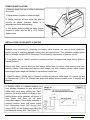
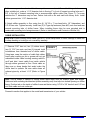
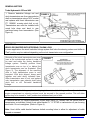
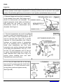
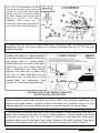
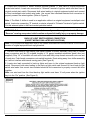
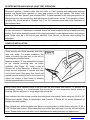
Installation Instructions
Hurst Pro-Matic 2 Truck Shifter
Fits most 2WD & 4WD Truck Applications
GM TH 350/400 / Ford C4/C6 / Mopar Torqueflite A727/A904
Catalog# 3838510
WORK SAFELY! For maximum safety, perform this installation on a clean, level surface and with the
engine turned off. Installation of this shifter requires working underneath vehicle. Raise front of
vehicle by lifting at points specified by the vehicle manufacturer. Place blocks or wedges in front of
and behind both rear wheels to prevent movement in either direction. DO NOT USE A BUMPER
JACK FOR SUPPORTING VEHICLE.
CAUTION: To avoid any possibility of bodily injury or damage to vehicle, do not attempt installation
until you are confident that the vehicle is safely secured and will not move.
IMPORTANT
1. All adjustments must be made with shifter and transmission in “Park”, “Neutral”, and “Low” gear
positions.
2. Adjustments are critical and must be precise.
3. Do not mix components (all parts including shifter cable must be genuine Hurst components
provided with kit).
4. If a shifter is removed and re-installed, adjustments must be checked and re-adjusted, if necessary.
5. When routing cable avoid sharp bends. Provide large full loops (if needed) for smooth shifting and
long cable life. Avoid routing cable near exhaust pipes as heat from the exhaust system will melt
cable casing. (Permanent damage of cable will result).
6. Always check cable for freedom of movement before connecting to shifter and transmission control
arm.
Failure to comply with any of the above may result in malfunction of shifter operation. Damage
to cable due to sharp bending, kinking, or excessive heat is not covered by Warranty.
These instructions detail the installation of the Hurst Quarter Stick Shifter for GM Powerglide 2 speed
transmission with both forward and reverse pattern valve bodies and GM Turbo TH 350/400 3 Speed
transmission with a reverse pattern valve body only. Please refer to the specific instructions for your
particular application for detailed information. See the illustration on page 4 for changing from 2
speed to 3 speed operation.
The shifter can be mounted directly to the floor with the four sheet metal screws supplied.
Technical Support (707) 544‐4761 1 www.hurst‐shifters.com CONSOLE INSTALLATION
1. Measure depth from top of shifter to below top
of console.
2. Adjust points of divider to measure depth.
3. Scribe contours of floor along the side of
console as shown. Maintain divider in a
perpendicular plane while scribing.
4. Trim portion below scribed line away. Fasten
console to shifter with two #8 x 1-3/4” Phillips
Head screws.
INSTALLATION OF PRO-MATIC 2 SHIFTER
1. Disconnect negative (-) battery cable.
Caution: when removing or connecting the battery cable terminal, use care to avoid intermittent
contact (arcing or sparking) between battery post and terminal end. This generates voltage spikes
that can damage sensitive ECM (Electronic Control Module) components or memory circuits.
2. Turn ignition key to “Unlock” position on steering column if equipped and place factory shifter in
“Neutral” position.
Column shift lever: remove drive pin that fastens shifter lever to column, then remove lever from
steering column. Disconnect and remove shift linkage rod from steering column inside engine
compartment and linkage rod attached to transmission control arm.
3. Place Pro-Matic 2 Shifter stick in “Neutral” position and remove shifter knob. Lift console up and
off. Remove one (1) #8 x 3/4” Phillips head screw that fastens chrome console cover to console and
separate.
4. Position shifter in a desired location on
floor allowing clearance for seat travel and
shifter stick travel when shifting into “Park”
position. Cut a small section of carpet or floor
matting where shifter assembly will mount to
floor (make sure there are no wires
underneath carpet). Place shifter assembly in
selected location, mark and center punch
four (4)mounting holes. Drill through floor
using a 9/32” drill bit. Deburr holes with a file
and sand with emery cloth. (See Figure 1).
Figure 1
FRONT OF
SHIFTER
Technical Support (707) 544‐4761 2 www.HURST‐SHIFTERS.com 5. If necessary, mark and cut a slit in the carpet to accommodate shifter cable. Using a hole saw or
other suitable tool, make a 1-1/2” diameter hole in flooring 3” in front of forward mounting hole and 13/4” to the left of forward mounting hole to accommodate shifter cable (See Figure 1). For some
vehicles the 3” dimension may be less. Deburr hole with a file and sand with emery cloth. Install
rubber grommet into 1-1/2” diameter hole.
6. Attach shifter assembly to floor using four (4) 1/4”-20 x 1” hex head bolts, 1/4” flatwashers, and
1/4”-20 hex nuts. Tighten securely. Install two (2) U-Type clip fasteners (Item #10) onto front and rear
console mounting tabs of shifter frame. When installing these clips be sure extruded side is
underneath mounting hole facing downward. (Refer to Identification and Contents of Shifter Kit).
CABLE INSTALLATION
CAUTION: When installing shifter cable (Item #12), avoid sharp bends or kinks. Damage to cable due
to sharp bending or kinking is not covered by warranty.
7. Remove 3/16” hex nut, two (2) rubber boots,
two (2) 7/16” hex nuts, and two (2) internal tooth
lockwashers from threaded end of shifter cable.
Using tape, wrap the section of cable that rubber
boots were covering so dirt or grease will not get
embedded inside cable housing causing cable to
scuff and bind. Insert cable from inside vehicle
through rubber grommet in floor. Route cable so
there are no sharp bends that would make the
shifter hard to operate. Be sure cable clears all
exhaust pipes by at least 1-1/2” (Refer to Figure
2).
FIGURE 2
Note: Use tie straps or clamps to secure shifter cable away from the exhaust pipes and engine.
Cable end with mounting tab attached (shifter assembly end) must slip into slotted opening on shifter
frame. Position tab on the inside of shifter frame and fasten using 1/4”-20 x 3/4” hex bolt and 1/4” hex
nut. Slide cable end onto cotter pin.
Proceed to section that applies to the model and transmission of your vehicle.
Technical Support (707) 544‐4761 3 www.HURST‐SHIFTERS.com GENERAL MOTORS
Turbo-Hydramatic 350 and 400
1. Remove backdrive linkage rod and
stock transmission arm from gear selector
shaft on transmission using a 9/16” socket
and replace with Hurst transmission arm
PT. 1058561 re-using stock bolt or nut.
Transmission arm must be installed with
round hole down and bend in arm
positioned away from transmission. (See
Figure 4).
FIGURE 4
IMPORTANT
VEHICLES EQUIPPED WITH STEERING COLUMN LOCK
In some applications the stock backdrive linkage system that locks the steering column and shifter in
“Park” position may be retained depending on the stock transmission arm configuration.
One side of the stock transmission arm must
have a flat unobstructed surface in order to
be used and retain the factory backdrive
linkage system. Carefully position Hurst
transmission arm on top of or behind the
stock transmission arm as illustrated. (See
Figure 3). The alignment of the mounting
slots in both transmission arms is very
important. With slots aligned, clamp arms
together and weld along indicated lines.
Allow transmission arm to cool, and replace
onto transmission gear selector shaft using
stock bolt or nut. Re-install backdrive
linkage.
FIGURE 3
Note: If the backdrive linkage system is not going to be retained, the linkage rod lever (located inside
engine compartment on steering column) must be secured in the upward position. This will allow
ignition key to be turned to “Lock” position and withdraw freely out of lock.
2. Remove the two (2) center transmission oil pan bolts (using 1/2” socket) from left (driver) side of
transmission as indicated. Attach Hurst cable bracket Pt. 117 4778Z to transmission oil pan re-using
stock bolts. Do not overtighten. (Refer to Figure 4).
Note: Hurst shifter cable bracket features slotted mounting holes to allow for adjustment of cable
forward or rearward.
Technical Support (707) 544‐4761 4 www.HURST‐SHIFTERS.com 3. Remove tape from cable and re-install rubber boots. Place shifter cable into mounting bracket on
transmission oil pan and secure using two (2) internal tooth lockwashers and two (2) 7/16” hex nuts
supplied with cable.
4. Be sure shifter is in “Neutral” position. Check and be sure transmission arm on gear selector shaft
is also in “Neutral” position. Thread cable pivot onto end of shifter cable. Adjust cable pivot until it
slides freely into hole in transmission arm. When properly adjusted, lock cable pivot in place using
3/16” hex nut. Insert cable pivot end into transmission arm so pivot end is facing outward away from
transmission. (See Figure 4 &7). Temporarily install cotter pin.
MOPAR
TORQUEFLITE A-727 & A-904
1. The stock backdrive linkage that locks shifter stick in “Park” position cannot be retained. Linkage
rod lever (located inside engine compartment on steering column) must be secured in the upward
position. This will allow ignition key to be turned to “Lock” position and withdraw freely out of lock.
2. Remove throttle lever located just
above transmission arm by removing the
bolt and nut, pry lever off the shaft using
a flatblade screwdriver. Remove linkage
and stock transmission arm. Install Hurst
Transmission arm Pt. 105 8564 using
the 1/4” x 1-1/2” hex bolt (Item #19), 1/4”
split lockwasher, and 1/4” hex nut
supplied. Re-install throttle lever and
linkage onto shaft. Check throttle lever
to be sure it operates freely. (See Figure
5).
Figure 5
3. Two (2) transmission oil pan bolts (driver side) directly below transmission arm must be removed.
Install cable bracket Pt. 117 8563, two (2) spacers, and two (2) 5/16”-18 x 3/4” hex head bolts
supplied. If transmission has a cast aluminum oil pan, spacers may not be needed.
4. Remove tape from cable and re-install rubber boots. Place shifter cable into mounting bracket on
transmission oil pan and secure using two (2) internal tooth lockwashers and two (2) 7/16” hex nuts
supplied with cable. (See Figures 2 and 5). It may be necessary to slightly bend the transmission
cooling lines to attain clearance for cable.
5. Make sure shifter is in “Neutral” position. Check and be sure transmission arm on gear selector
shaft is also in “Neutral” position. Thread cable pivot onto end of shifter cable. Adjust cable pivot until
it slides freely into hole in transmission arm. When properly adjusted, lock cable pivot in place using
3/16” hex nut. Insert cable pivot into transmission arm so pivot end is facing outward away from
transmission. (See Figure 5). Temporarily install cotter pin.
Technical Support (707) 544‐4761 5 www.HURST‐SHIFTERS.com FORD
C-4 & C-6
1. The stock backdrive linkage that locks shifter stick in “Park” position cannot be retained. Linkage
rod lever (located inside engine compartment on steering column) must be secured in the upward
position. This will allow ignition key to be turned to “Lock” position and withdraw freely out of lock.
2. Remove linkage and lever that is connected
to the downshift lever shaft. Shift linkage rods
should be disconnected and discarded. The
original equipment neutral safety and back-up
light switch that are found on some ford
transmissions should be disconnected and
discarded. (See Figure 6).
3. The stock transmission arm must be modified
in order to install Hurst transmission arm Pt. 105
8559. Lower section of stock transmission arm
must be removed (See Figure 6A) to provide
clearance for Hurst transmission arm. Using a
hacksaw, cut shaded section of transmission
arm off so remaining arm is completely flat.
Install Hurst transmission arm onto stock
transmission arm pointing downward, with bend
in arm away from transmission. Use 1/4” x 1-1/2”
hex bolt, 1/4” split lockwasher, and 1/4” hex nut
to secure Hurst transmission arm in place. Reinstall downshift lever, make sure o-ring is in
position before installing lever onto shaft.
Downshift lever must move freely.
Figure 6
Figure 6A
4. C-4: Two (2) lower bolts (E) on the rear
servo cover (F), must be removed. Install Hurst
cable bracket Pt. 117 8558 onto servo cover,
re-using factory bolts and tighten securely.
Figure 6B
(See Figure 6B).
Technical Support (707) 544‐4761 6 www.HURST‐SHIFTERS.com C-6: Two (2) transmission oil pan
bolts at the left rear corner must be
removed to install the Hurst cable
bracket and two (2) spacers. Install
the cable bracket onto the oil pan
using the 5/16”-18 x 3/4” bolts
(supplied). (See Figure 6C). If
transmission has a cast aluminum oil
pan, spacers may not be necessary.
Figure 6C
5. Remove tape from cable and re-install rubber boots. Place shifter cable into mounting bracket on
transmission oil pan and secure using two (2) internal lockwashers and two (2) 7/16” hex nuts
supplied with cable.
6. Make sure shifter is in “Neutral” position.
Check and be sure transmission control arm
gear selector shaft is in “Neutral” position.
Thread cable pivot onto end of shifter cable.
Adjust cable pivot until it slides freely into
hole in transmission arm. When properly
adjusted, lock cable pivot in place using
3/16” hex nut. Insert cable pivot end into
transmission arm so pivot end is facing
outward away from transmission. (See
Figure 6 &7). Temporarily install cotter pin.
Figure 7
NEUTRAL/PARK START WIRING CONNECTION
(EXCEPT MOPAR APPLICATIONS)
Important: The Pro-Matic 2 shifter uses an electrical neutral/park start switch that replaces the
original equipment neutral safety switch on most Chevy, GMC, Ford, and Mopar applications. The
original neutral safety switch is typically located at the lower end of steering column. For your
particular application refer to the vehicle manufacturer’s service manual for the correct location.
1. Pre-wire Hurst neutral/park start switch (front switch located on shifter assembly) using two (2)
female crimp connectors (Item #22) and two (2) suitable lengths of 16 gauge insulated automotive
grade wire (not supplied). Strip 1/4” of insulation off each end of wire and firmly crimp female
connector onto one end of each wire. Push female connectors onto switch terminals. Route wiring
away from shifter assembly so it will not interfere with internal moving parts. (Refer to Figure 8).
Technical Support (707) 544‐4761 7 www.HURST‐SHIFTERS.com 2. Locate wire connected to starter solenoid terminal marked “S” and trace to original equipment
neutral start switch. Locate wire connected to “Solenoid” terminal of ignition switch and also trace to
original neutral start switch. Disconnect both wires leading to original equipment switch and connect
to Hurst neutral/park start switch wire leads. Use correct size insulated electrical butt connectors to
properly connect the wires together. (Refer to Figure 8).
Note: If Pro-Matic 2 shifter is used in an application without an original equipment neutral/park start
switch, locate wire connecting “S” terminal on starter solenoid to “Solenoid” terminal of ignition switch.
Cut this wire and splice in the Hurst neutral park/start switch.
WARNING: Failure to wire and connect switch correctly can allow engine to start in “Drive” or
“Reverse” causing unexpected vehicle motion and possible bodily injury or property damage.
BACK-UP LIGHT SWITCH WIRING CONNECTION
(EXCEPT MOPAR 1969-LATER APPLICATIONS)
Note: For your particular application refer to the vehicle manufacturer’s service manual for the correct
location of original equipment back-up light switch.
1. Pre-wire Hurst back-up light switch (rear switch located on shifter assembly) using two (2) female
crimp connectors and two (2) suitable lengths of 16 gauge insulated automotive grade wire (not
supplied). Strip 1/4” of insulation off each end of wire and firmly crimp female connector onto one end
of each wire. Push female connectors onto switch terminals. Route wiring away from shifter assembly
so it will not interfere with internal moving parts (See Figure 8).
2. Locate wire lead connected to back-up lights and trace to the original equipment back-up light
switch. Disconnect both wires leading to the back-up light switch and connect to Hurst back-up light
switch wire leads. Use correct size insulated electrical butt connectors to properly connect the wires
together.
Note: one wire lead from the Hurst back-up light switch must have 12 volt power when the ignition
key is in the “On” position. (See Figure 8).
Figure 8
Technical Support SHIFTERS.com (707) 544‐4761 8
www.HURST‐
Mopar
Technical Support (707) 544‐4761 8 www.HURST‐SHIFTERS.com Applications
1969-Later
The original equipment factory back-up light switch is located on the transmission. No additional
wiring necessary.
SHIFT INDICATOR LAMP SOCKET WIRING CONNECTION
Use a suitable length of 22 gauge insulated automotive grade wire (not supplied). Strip 1/4” of
insulation off each end of wire. Connect lead wire from light assembly to this wire using the correct
size electrical butt connector. Connect other end of wire to electrical circuit of instrument panel lights.
Important: The shifter assembly must have a good chassis “ground” for indicator lamp to work
properly.
SHIFTER OPERATION
Caution: Before testing shifter operation, it is recommended that vehicle be placed back on the
ground, parking brake applied, and wheels blocked. Vehicle should be parked in a safe location for
testing. Be sure no one is in front of or behind during testing.
Apply brake pedal pressure while testing.
Familiarize yourself with the operation of this
shifter by moving the shifter stick backward
and forward through entire shift pattern (See
Figure 9).
Move stick through each gear selection,
counting positions as you feel them: P-R-ND-2-1
Figure 9
Cable pivot attached to transmission control arm should be checked in “Park”, “Neutral, and “Low”
gear positions to be sure pivot slides freely “IN” and “OUT” of transmission arm. Move shifter stick
into “Low” gear and check adjustment underneath vehicle by removing cotter pin and cable pivot from
transmission arm. Check to be sure that transmission is FULLY ENGAGED in “Low” gear. When
cable adjustment is correct, shifter will engage “Park” and “Low” gears completely. Once adjustment
is made, secure cotter pins on either end of shifter cable and be sure all adjustment bolts and nuts
are tightened securely.
WARNING: Correct cable adjustment is mandatory to insure that when shifter is in “Park” position,
transmission is also fully into the “Park” detent. Failure to adjust cable correctly could result in
unexpected vehicle motion when shifter is in “Park” or “Neutral” positions.
Technical Support (707) 544‐4761 9 www.HURST‐SHIFTERS.com STARTER MOTOR AND BACK-UP LIGHT TEST OPERATION
We recommend disconnecting the “batt” wire from distributor so engine will crank but not start.
Reconnect negative (-) battery cable. With the shifter in “Park” position and brake pedal pressure
applied, test starter motor operation in every gear position of the shift pattern. The starter must
operate in “Park” and “Neutral” gear positions ONLY. If starter operates in any other gear position, recheck wiring to be sure connections and adjustments of switches are correct. Test operation of backup lights, they should operate in “Reverse” only. Turn “On” instrument panel and check illumination of
gear indicator lamp.
Note: The Hurst neutral/park start switch and back-up light switch are pre-adjusted from the factory
for your convenience. If adjustment is needed, loosen the screw located at the top of switch mounting
bracket. Pivot switch assembly inward until the required contact is made between switch and actuator
plate. Shifter must be in the correct gear selection: Park, Neutral, or Reverse when making this
adjustment.
CONSOLE INSTALLATION
Note: In some applications shifter console must be trimmed to fit the contour of floor tunnel.
Place console over shifter assembly and hold it
level with shifter. For proper installation, the
inside of console top must rest on the two (2)
mounting tabs of shifter frame.
Measure distance “A” from underside of console
to the console mounting tabs on shifter
assembly (See Figure 10). Using a pair of
dividers set to the dimension of distance “A”,
touch one end of dividers to console and other
end to floor tunnel. Drag along floor tunnel and
against console scribing a line on the console to
match the contour of floor tunnel by keeping
dividers perpendicular to floor tunnel.
Figure 10
Using a utility knife, carefully score a firm cut over the line scribed into console. To prevent any
unnecessary cracking, it is recommended that console be at room temperature before cutting or
trimming. Remove any burrs or rough edges with a small file.
Insert indicator lens into chrome console cover and place onto console, fasten using two (2) #8 x 3/4”
Phillips head screws. (Refer to Identification and Contents of Shifter Kit for correct placement of
indicator lens and screws).
Place console onto shifter assembly and fasten to mounting tabs on shifter frame using two (2) #8 x
1-3/4” Phillips head screws. Slide rubber boot over shifter stick and work it into the chrome console
cover. Thread shifter knob onto stick, turn to desired position and tighten jam nut against knob.
Technical Support (707) 544‐4761 10 www.HURST‐SHIFTERS.com GENERAL MOTORS VEHICLES EQUIPPED WITH STEERING COLUMN LOCK
Once all adjustments have been made and shifter functions properly, check operation of steering
column lock. It must operate in “Park” position ONLY. It is very important that the column lock be
adjusted correctly so that when shifter is placed into “Park” position, ignition key can be turned to
“Lock” position. Steering wheel should lock and key should withdraw freely out of lock. The shifter
then must not be able to move in any other gear position. If the shifter can be moved to other gear
positions, column lock is not adjusted correctly and must be re-adjusted.
SHIFTER OPERATION
GEAR SHIFT PATTERN CHANGES / UPPER GATE MODE - GEAR SELECTION
The upper gear selection gate of the shifter operates “Park” and “Reverse”. When in “Park” position,
the shifter stick must be lifted to clear the safety stop between “Park” and “Reverse”, then pulled
straight back to engage “Reverse”. Once in “Reverse”, the handle will drop down slightly and shifter is
ready to be pulled straight back to “Neutral”. When “Neutral” is engaged the stick will drop again and
enter the lower gate (ratchet mode) of shifter. (See Figure 9).
LOWER GATE RATCHET MODE - GEAR SELECTION
The lower gear selection gate of the shifter operates “Neutral”, “Drive 3”, “Drive 2”, and “Drive 1” (low
gear). The shifter stick ratchets back and forth from “Neutral” to “Drive 1”.
DOWNSHIFTING
Lift stick, pull back to next detent for “Reverse”.
Stick will drop down slightly.
Pull back to next detent for “Neutral”.
Stick will drop down again.
Push down then pull back to stop position and
release for “Drive 3”.
Pull back again to stop position and release
for “Drive 2”.
Pull back again to stop position and release
for “Drive 1”.
Park to Reverse
Reverse
Neutral to Drive 3
Drive 3 to Drive 2
Drive 2 to Drive 1
UPSHIFTING
Push stick forward to stop position and release
for “Drive 2”.
Push stick forward again to stop position and
release for “Drive 3”.
Push stick forward to stop position and release
for “Neutral”.
Lift stick upward, push forward to next
detent for “Reverse”.
List stick upward, push forward to
stop position for “Park”.
Drive 1 to Drive 2
Drive 2 to Drive 3
Drive 3 to Neutral
Neutral to Reverse
Reverse to Park
Technical Support (707) 544‐4761 11 www.HURST‐SHIFTERS.com TOOLS REQUIRED FOR INSTALLATION
2 or 4 Automotive Support Stands
Car Ramps
1-1/2” Hole Saw
9/32” Drill Bit
Tin Snips
Hacksaw (Ford Only)
Hammer
File
Center Punch
Wire Strippers
Wire Crimping Tool
1/8” Drift Punch
12-Volt Test Light or Voltmeter
Electric Drill
Tape Rule
Electrical Tape
Pliers
Flat Blade Screwdriver
Phillips R Tip Screwdriver
Ratchet-3/8” Drive
10” long Extension-3/8” Drive
7/16” Socket - 3/8” Drive
1/2” Socket - 3/8” Drive
9/16” Socket - 3/8” Drive
3/8” Wrench-Open End
7/16” Wrench-Open End
11/16” Wrench-Open End
Fluorescent Work Light
CONTENTS OF SHIFTER KIT
GENERAL MOTORS
3-SPEED TURBO-HYDRAMATIC 350 & 400
1. Shifter Knob
2. Phillips Head Sheet Metal Screw # 8 x 3/4”
3. Phillips Head Sheet Metal Screw #8 x 1-3/4”
4. Rubber Boot
5. Console Cover
6. Indicator Lens
7. Console
8. Shifter Assembly
9. Hex Head Bolt 1/4”-20 x 1”
10. U-Type Clip Fastener 1/4”-20 x 3/4”
11. Indicator Light Assembly
12. Shifter Cable
13. Rubber Grommet 1-1/2” Diameter
14. Hex Head Bolt 1/4”-20 x 3/4”
15. Hex Nut 1/4”-20
16. Flat Washer 3/16” I.D.
17. Cottern Pin 1/16”
18. Cable Pivot
19. Hex Head Bolt 1/4”-20 x 1-1/2”
20. Flat Washer 1/4” I.D.
21. Hex Head Bolt 5/16”-18 x 3/4”
22. Female Wire Connector
23. Split Lockwasher 1/4” I.D.
1630064
97093105 (2)
97093106 (2)
1148550
1958551
1690005
1298554
3830510
97080969 (4)
97093081 (2)
1660004
5008555
97093109
97090029
97000910 (6)
97000905
97093086 (2)
97X93089
97000913
97000818 (4)
97000416 (2)
2527600 (4)
97090082
24. Bracket-Shifter Cable TH 350 & 400 1174778Z
25. Transmission Arm TH 350 & 400
1058561
MOPAR
3-SPEED TORQUEFLITE A-727 & A-904
26. Bracket-Shifter Cable
A-727 & A-904
27. Transmission Arm
A-727 & A-904
28. Spacers-Cable Bracket
1178563
1058564
97093092
FORD
3-SPEED TORQUEFLITE A-727 & A-904
29. Bracket-Shifter Cable C-4
30. Bracket-Shifter Cable C-6
31. Transmission Arm
C-4 & C-6
1178558
1178557
1058559
Technical Support (707) 544‐4761 12 www.HURST‐SHIFTERS.com IMPORTANT: RETAIN THESE INSTRUCTIONS FOR FUTURE REFERENCE
Technical Service
A highly trained technical service department is maintained by Hurst Performance to answer your
technical questions, provide additional product information and offer various recommendations.
Technical service calls, correspondence, and warranty questions should be directed to:
Hurst Performance Products
(707) 544-4761
www.Hurst-Shifters.com
Technical Support (707) 544‐4761 13 www.HURST‐SHIFTERS.com