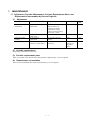
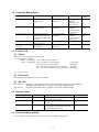
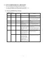
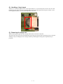
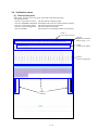
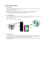
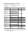
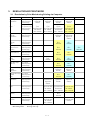
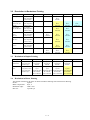
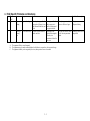
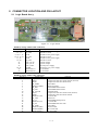
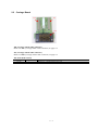
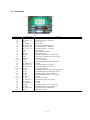
1
PIXUS 470PD
i470D
SERVICE MANUAL
Revision 0
QY8-1387-000
COPYRIGHT 2003 CANON INC. CANON PIXUS 470PD / i470D 032003 C A 0.00 -0
Scope
This manual has been issued by Canon Inc., to provide the service technicians of this product with the
information necessary for qualified persons to learn technical theory, maintenance, and repair of products. The
manual covers information applicable in all regions where the product is sold. For this reason, it may contain
information that is not applicable to your region.
Revision
This manual could include technical inaccuracies or typographical errors due to improvements or changes
made to the product. When changes are made to the contents of the manual, Canon will release technical
information when necessary. When substantial changes are made to the contents of the manual, Canon will
issue a revised edition.
The following do not apply if they do not conform to the laws and regulations of the region where the manual or
product is used:
Trademarks
Product and brand names appearing in this manual are registered trademarks or trademarks of the respective
holders.
Copyright
All rights reserved. No parts of this manual may be reproduced in any form or by any means or translated into
another language without the written permis sion of Canon Inc., except in the case of internal business use.
Copyright 2003 by Canon Inc.
CANON INC.
iPrinter Products Quality Assurance Div.
16-1, Shimonoge 3-chome, Takatsu-ku, Kawasaki, Kanagawa 213-8512, Japan
I. MANUAL OUTLINE
This manual consists of the following three parts to provide information necessary to service the i470D:
Part 1: Maintenance
Information on maintenance and repair of the i470D
Part 2: Technical Reference
New technology and technical information such as FAQ’s (Frequently Asked Questions) of the i470D
Part 3: Appendix
Block diagrams and pin layouts of the i470D
Reference:
This manual does not provide sufficient information of disassembly and reassembly procedures. Refer to the
graphics in the separate Parts Catalog.
II. TABLE OF CONTENTS
Page
1-1
1-1
1-2
1-2
1-2
1-2
1-3
1-3
1-4
1-4
1-5
1-6
1-6
1-7
1-9
1-12
1-14
Part 1: MAINTENANCE
1.
MAINTENANCE
1.1 Adjustment, Periodic Maintenance, Periodic Replacement Parts, and Replacement
Consumables by Service Engineer
1.2 Customer Maintenance
1.3 Product Life
1.4 Special Tools
1.5 Serial Number Location
2. LIST OF ERROR DISPLAY / INDICATION
2.1 Operator Call Errors (by LED Blinking in Orange)
2.2 Service Call Errors (by LED Blinking in Orange and Green Alternately, or Lit in
Orange)
2.3 Warnings
2.4 Troubleshooting by Symptom
3. REPAIR
3.1 Notes on Service Part Replacement (and Disassembling/Reassembling)
3.2 Special Notes on Repair Servicing
3.3 Adjustment / Settings
3.4 Verification Items
4. PRINTER TRANSPORTATION METHOD
Part 2: TECHNICAL REFERENCE
2-1
2-2
2-3
2-3
2-4
2-4
2-4
2-5
1. NEW TECHNOLOGIES
2. CLEANING MODE AND AMOUNT OF INK PURGED
3. RESOLUTION BY PRINT MODE
3.1 Resolution by Print Mode during Printing via Computer
3.2 Resolution in Borderless Printing
3.3 Resolution in Duplex Printing
3.4 Resolution in Direct Printing
4. FAQ (Specific Problems and Solutions)
Part 3: APPENDIX
3-1
3-2
3-2
3-7
3-8
3-9
1. BLOCK DIAGRAM
2. CONNECTOR LOCATION AND PIN LAYOUT
2.1 Logic Board Ass’y
2.2 Carriage Board
2.3 Print Head
2.4 i470D / PIXUS 470PD Specifications
Part 1
MAINTENANCE
1. MAINTENANCE
1.1 Adjustment, Periodic Maintenance, Periodic Replacement Parts, and
Replacement Consumables by Service Engineer
(1)
Adjustment
Adjustment
EEPROM
initialization
At logic board ass’y
replacement
Destination settings
At logic board ass’y
replacement
At ink absorber
replacement
At print head or logic
board ass’y replacement
Waste ink counter
resetting
Print head alignment
To initialize settings other
than the following:
- USB serial number
- Destination setting
- On -arrival cleaning flag
- Waste ink counter
To set the destination.
None
Approx.
time
1 min.
None
1 min.
To reset the waste ink
counter.
To ensure accurate dot
placement.
None-
1 min.
Computer
(settings via
the printer
driver)
2 min.
Timing
Purpose
Tool
(2) Periodic maintenance
No periodic maintenance is necessary.
(3) Periodic replacement parts
There are no parts in this printer that require periodic replacement by a service engineer.
(4) Replacement consumables
There are no consumables that require replacement by a service engineer.
1-1
1.2 Customer Maintenance
Adjustment
Timing
Purpose
Print head alignment
At print head
replacement.
Print head cleaning
When print quality is
not satisfying.
Print head deep cleaning
When print quality is
not satisfying, and not
improved by print head
cleaning.
When an ink tank
becomes empty.
When paper does not
feed properly.
Ink tank replacement
Paper feed roller
cleaning
Tool
To ensure accurate dot Printer, or
placement.
computer
(settings via the
printer driver)
To improve nozzle
Printer, or
conditions.
computer
(settings via the
printer driver)
To improve nozzle
Printer, or
conditions.
computer
(settings via the
printer driver)
----To clean the paper
feed rollers.
Approx.
time
5 min.
30 sec. to
1 min.
1.5 to 2.5
min.
2 min.
----None.
2 min.
1.3 Product Life
(1) Printer
The value (i) or (ii), whichever comes first.
(i) 4,000 pages of printing
- Black: 1,200 pages (A4, 1,500 character pattern)
- Color: 2,800 pages (A4, 7.5% duty per color pattern:
1,300 pages
A4, 30% duty per color pattern:
500 pages
100 x 148 mm, 30% duty per color pattern:
700 pages
89 x 127 mm size, 30% duty per color pattern: 300 pages)
(ii)
5 years of use
(2) Print head
4,000 pages of printing (in the above print mode)
(3) Ink tank
BCI-24Black:
BCI-24Color:
300 pages (1,500 character pattern in black printing, plain paper, standard mode)
580 pages (ISO JIS-SCID No. 5 pattern, plain paper, standard mode)
160 pages (ISO JIS-SCID No. 5 pattern, plain paper, standard mode)
1.4 Special Tools
Name
FLOIL KG107A
Tool No.
QY9-0057-000
MOLYKOTE 7508
CK-0562-000
ELECTRICITY IF-20
CK-8006-000
Purpose
To improve the sliding property of the
carriage shaft (QC1-2196)
To improve the sliding property of the
LF gear
To improve the sliding property between
the grounding spring (QA4-1372) and
the feed roller (QF4-0212)
1.5 Serial Number Location
On the right side with the access cover opened (on the carriage cable holder)
1-2
Remarks
2. LIST OF ERROR DISPLAY / INDICATION
Errors and warnings are indicated by the following methods:
(1) Errors are displayed by the number of times the LED blinks.
(2) Errors are displayed by the number displayed on the operation panel.
(3) Warnings are displayed via the printer driver status monitor.
2.1 Errors by LED Blinking in Orange
User recoverable errors
LED
blinking in
orange
2 times
Panel display
Error Code
Error
301
1000
No paper.
3 times
302
1300
Paper jam.
6 times
402
1401
Solution
Set the paper, and press the
Resume/Cancel button.
Remove the jammed paper, and
press the Resume/Cancel button. If
the error is not resolved, check that
no foreign material is inside the
printer.
Install the print head, and close the
access cover.
Re-install the print head, or with
the print head installed, turn the
printer off and on. If the error is not
resolved, replace the print head.
Pressing the Resume/Cancel button
will exit the error.
(The waste ink absorber full error
occurs at 100% capacity, making it
impossible to perform printing.
Disconnect the USB cable to the
digital camera, and press the
Resume/Cancel button.
The print head is not
installed.
7 times
403
The print head is not
1405
installed properly.
(EEPROM data of the
print head is faulty.)
8 times
202
Warning: The waste ink
1700
absorber becomes almost
full (to approx. 95% to
100% of the maximum
capacity).
11 times
611
Digital camera
2001
transmission time-out
error (When the printer
cannot communicate with
a digital camera, the
time-out error occurs.)
612
Digital camera
Disconnect the USB cable, and
2001
non-supporting device
press the Resume/Cancel button.
error (When a digital
camera or device other
than a digital camera, not
supporting Direct
Printing is connected to
the printer with the USB
cable, the error occurs.)
*1:The error code is stored in the operator / service call history of the EEPROM information.
1-3
2.2 Errors by LED Blinking in Orange and Green Alternately, or Lit in Orange
User unrecoverable errors
LED
alternate
blinking in
orange and
green
2 times
Panel display
Error Code
Error
Solution
802
5100
Carriage error
4 times
804
5C00
Purge unit error
6 times
806
5400
Internal temperature error
7 times
807
5B00
Waste ink absorber full error
8 times
808
5200
Print head temperature rise
error
1. Check that no foreign material
is inside the printer.
2. Replace the timing slit strip
film.
3. Replace the purge unit.
4. Replace the logic board ass’y.
1. Check that no foreign material
is inside the printer.
2. Replace the purge unit.
3. Replace the logic board ass’y.
1. Turn the printer off, and after a
short period of time, turn the
printer on again.
2. Replace the logic board ass’y.
1. Replace the ink absorber.
2. Replace the logic board ass’y.
1. Turn the printer off, and after a
short period of time, turn the
printer on again.
2. Replace the print head.
3. Replace the logic board ass’y.
Replace the logic board ass’y.
Replace the logic board ass’y.
9 times
809
EEPROM error
6800
Lights in
No display
RAM error
6800
orange
*1:The error code is stored in the operator / service call history of the EEPROM information.
2.3 Warnings
Printer (no LED indications)
Displayed warning
Remarks
Low black ink warning 1 (About half of the full amount remains.)
Low color ink warning 1 (About half of the full amount remains.)
Low black ink warning 2 (Little ink remains. “!”)
Low color ink warning 2 (Little ink remains. “!”)
The status is displayed on the BJ printer
driver status monitor.* 1
Low black ink warning 3 (An unknown amount remains. “?”)
Low color ink warning 3 (An unknown amount remains. “?”)
Print head temperature rise warning
If the print head temperature is high
when the access cover is opened, the
warning is displayed.* 2 When the print
head temperature falls, the warning is
released.
Protection at excess rise of the print head temperature
If the print head temperature exceeds the
specified limit, a Wait is inserted during
printing. When the print head
temperature falls, printing will resume
automatically.
* 1 : Only when the remaining ink amount detection function is enabled. (When disabled, there is no status
display.)
* 2 : At the warning, the carriage does not move to the ink tank replacement position when the access cover is
opened.
1-4
2.4 Troubleshooting by Symptom
Faulty
operation
Symptom
The power does not turn on.
The power turns off
immediately after power-on.
The print head is not
recognized.
The print head does not move to
the home position.
A strange noise occurs.
Solution
1. Replace the AC adapter.
2. Replace the logic board ass’y.
3. Replace the operation panel unit.
1. Remove and re -install the print head.
2. Replace the print head.
3. Replace the logic board ass’y.
1. Check that no foreign material is inside
the printer.
2. Attach a removed part if any.
3. Apply oil to the grounding spring.
Paper does not feed.
1. Remove foreign material if any.
Paper feed
2. Replace the sheet feeder unit.
problems
Paper feeds at an angle.
1. Remove foreign material if any.
2. Adjust the paper guide position.
No printing, or no color ejected. 1. Check whether ink remains or not.
2. Perform print head deep cleaning.
3. Replace the print head.
4. Replace the logic board ass’y.
Printing is faint, or white lines
1. Remove and re -install the print head.
appear on printouts even after
2. Check whether ink remains or not.
print head cleaning.
3. Perform print head deep cleaning.
Line(s) not included in the print 4. Replace the print head.
data appears on printouts.
5. Replace the logic board ass’y.
Paper gets smeared.
1. Feed several sheets of paper.
2. Clean the paper path with cotton swab or
cloth,
3. Replace the platen unit.
Unsatisfactory
A part of a line is missing on
1. Replace the ink tank.
print quality
printouts.
2. Replace the print head.
Color hue is incorrect.
1. Check whether ink remains or not.
2. Perform print head deep cleaning.
3. Replace the print head.
4. Replace the logic board ass’y.
No ejection of black ink.
1. Check whether ink remains or not.
2. Perform Refreshing.
3. Replace the print head.
Graphic or text is extended on
1. Clean the timing slit strip film with
printouts.
alcohol.
2. Replace the timing slit strip film.
3. Replace the logic board ass’y.
4. Replace the carriage unit.
Card is not recognized.
1. Confirm the card installation status.
2. Release the maintenance mode.
3. Format the card on the digital camera.* 1
4. Replace the logic board ass’y.
Image data is not recognized.
1. Check that images exist in the card.
Direct
2. Check the data volume in the card, and
Printing-related
format type.
problems
3. Replace the logic board ass’y.
4. Replace the operation panel.
Digital Camera Direct Printing
1. Check that the printer supports Digital
cannot be performed.
Camera Direct Printing.
2. Check that no errors occur in the printer.
3. Replace the logic board ass’y.
* 1 : If image data is in the card, move the data to the host computer before formatting.
1-5
Part No.
QH3-3615
QM2-0483
QH8-1267
QY6-0047
QM2-0483
QA4-1372
QG4-0374
QY6-0047
QM2-0483
QY6-0047
QM2-0483
QG4-0380
QY6-0047
QY6-0047
QM2-0483
QY6-0047
QA4-0918
QM2-0483
QG4-0348
QM2-0483
QM2-0483
QH8-1267
QM2-0483
3. REPAIR
3.1 Notes on Service Part Replacement (and Disassembling/Reassembling)
Service part
Logic board ass’y
(QM2-0483)
Notes on replacement*1
- Do not bend the 4 in 1
connector pin.
Ink absorber
(QA4-0212/0213)
Timing slit strip film
(QA4-0918)
Purge unit
- Upon contact with the film,
wipe the film with alcohol.
- Confirm no grease is on the
film. (Wipe off any grease
thoroughly with ethanol.)
- Do not bend the film.
Remove the carriage shaft
(QC1-2196), and then the purge
unit.
Print head
(QY6-0047)
Adjustment/settings*2
Operation check
After replacement:
1. Initialize the EEPROM.
2. Set the destination in the
EEPROM.
3. Perform the print head
alignment in the user
mode.
4. Perform the print head
cleaning 1 time.
After replacement:
- Reset the waste ink
counter.
- Service test print
After replacement:
- Perform the print head
alignment in the user
mode.
- Service test print
After replacement:
- Perform the print head
alignment in the user
mode.
- Service test print
- Service test print
* 1 : General notes:
- Make sure that the flexible cables and wires in the harness are in the proper position and connected
correctly. See page 1-7 (1), for details.
- Do not drop the ferrite core, which may damage it.
- Protect electrical parts from damage due to static electricity.
- Do not touch the timing slit strip film. No grease or abrasion is allowed.
- Protect the units from ink contamination.
- Do not loosen red screws.
1-6
3.2 Special Notes on Repair Servicing
(1) Cable wiring
Exercise caution when handling the DC connector and motor cable wiring. For wiring, be sure to use ties,
cores and dampers. Improper wiring or wiring without any ties, cores and dampers may cause printer
malfunction due to noise or electrostatic discharge.
<Cable wiring>
Fix the DC harness, PG motor cables, PG sensor
cables and CR motor cables with a tie.
Fix the PG sensor cables and
CR motor cables in the claw.
Fix the DC cables and PG
motor cables in the damper.
Fix the LF motor cables
with the core.
1-7
(2) Handling of logic board
As the 4 in 1 connector pin functions on the logic board ass’y can be easily bent, exercise care to avoid
bending the pins when removing or installing the connector on the logic board. If pins are bent, a card
non-recognition failure or a Direct Printing failure may occur.
(3) Removing the purge unit
When removing the purge unit, the carriage shaft must be removed in advance.
The purge unit cannot be removed without first removing the carriage shaft. If the purge unit is removed
forcibly, it may be damaged, or the carriage shaft may be damaged, causing uneven print density in
printouts.
1-8
3.3 Adjustment / Settings
(1) User mode
The printer is operated through the Resume/Cancel button or operation panel.
<Operation via the Resume/Cancel button>
1) Turn on the printer.
2) Press and hold the Resume/Cancel button until the LED blinks in green the specified number of times
listed in the table below, and release the button. The operation will start.
LED blinking
1 time
2 times
3 times
4 times or more
Operation
Manual cleaning
Nozzle check pattern printing
Paper feed roller cleaning
No operation
Remarks
Cleaning both black and color simultaneously.
The operation can also be performed from the printer
driver utility.
<Operation via the operation panel>
1) Press the Maintenance button.
2) Using the Left/Right cursor buttons, change the number displayed in the operation panel for the desired
function listed in the table below, and press the Set button to execute the function.
Panel Display
01
02
03
04
05
06
Function
Nozzle check pattern printing
Print head manual cleaning
Print head deep cleaning
Print head alignment
Ink counter reset
Ink remaining display setting
07
Date order setting in date print
Remarks
- Cleans black and color simultaneously.
- Cleans black and color simultaneously.
Using the printout, set the optimum values.
Set the ink remaining counter to 100%.
Ink remaining icon is displayed or not displayed on
the operation panel.
The following three date orders are possible.
1. Year, month, date
2. Month, date, year
3. Date, month, year
1-9
(2) Service mode
Function
Service test print
EEPROM information print
EEPROM initialization
Waste ink counter reset
Destination settings
Print head deep cleaning
Operation panel display
confirmation
Procedures
See “Service mode operation
procedures” below.
See “Service mode operation
procedures” below.
See “Service mode operation
procedures” below.
Remarks
Set a sheet of A4/LTR- or larger-sized paper.
For print sample, see page 1-12.
Set a sheet of A4/LTR- or larger-sized paper.
For print sample, see page 1-13.
The following items are not initialized:
- USB serial number
- Destination settings (Japan / Overseas)
- Cleaning flag on arrival
- Waste ink counter
See “Service mode operation
Both the main and the borderless print waste
procedures” below.
ink counters are reset at the same time.
See “Service mode operation
Overseas: i470D
procedures” below.
Japan:
PIXUS 470PD
Cleans black and color, simultaneously.
See “Operation panel operation Confirm the operations of operation panel
confirmation procedures”
display and operation buttons. Perform the
below.
confirmation at operation panel replacement.
<Service mode operation procedures>
1) Close the access cover, and turn off the printer. While pressing the Resume/Cancel button, press and
hold the Power button. (The LED lights in green to indicate that a function is selectable.)
2) While holding the Power button, release the Resume/Cancel button.
3) While holding the Power button, press the Resume/Canc el button 2 times, and then release the Power
and Resume/Cancel buttons. (In the operation panel, “02” will be displayed. Each time the
Resume/Cancel button is pressed, the LED lights alternately in either orange or green. During
initialization, the LED blinks in green.)
4) When the LED stops blinking and lights in green, press the Resume/Cancel button the specified number
of time(s) according to the function listed in the table below. (Each time the Resume/Cancel button is
pressed, the LED lights alternately in either orange or green.)
Time(s) LED
0 times Green
Power off
1 time
Orange
Service test print
2 times
Green
EEPROM information print
3 times
4 times
5 times
Orange
Green
Orange
EEPROM initialization
Waste ink counter resetting
Destination settings
6 times Green
7 times Orange
8 times Green
or more
Function
Print head deep cleaning
Not used in servicing
Return to the menu selection
Remarks
When the print head is not installed, the carriage returns
and locks in the home position.
When the Power button is pressed during printing, printing
stops, and the mode returns to step 4) above.
When the Power button is pressed during printing, printing
stops, and the mode returns to step 4) above.
Proceed to the following steps 5) and then 6) to set the
destination.
Cleans black and color, simultaneously.
Return to step 4) above.
5) After the function (menu) is selected, press the Power button. The LED lights in green, and the selected
function is performed. (When the operation completes, the printer returns to step 4) above.)
<Destination setting>
6) Press the Resume/Cancel button the specified number of time(s) according to the destination listed in
the table below, and then the Power button.
Time(s)
1 time
2 times
LED
Orange
Green
Destination
Overseas: i470D
Japan:
PIXUS 470PD
1 - 10
<Operation panel operation verification procedures>
After performing the above service mode operation procedures up to step 3) (with “02” indication in the
operation panel), press the specified operation button. Icons are displayed on the LCD as shown below to
verify the operation buttons and panel displays.
1) When pressing the left Cursor button
2) When pressing the right Cursor button
3) When pressing the Set button
4) When pressing the Maintenance button
5) When pressing the Photo Viewer button
6) When pressing the Print button
7) When pressing the Cancel button
1 - 11
3.4 Verification Items
(1) Service test print
After repair, print the service test print, and confirm the following items:
<Print quality items>
- Check 1, top of form accuracy: The line shall be within the paper.
- Check 2, EEPROM information: Destination and waste ink counter shall be checked.
- Check 3, nozzle check pattern: Ink shall be ejected from all nozzles.
- Check 4, vertical straight lines: The lines shall not be broken.
- Check 5, halftone:
There shall be no remarkable streaks or unevenness.
Check 1:
Top of form accuracy
Check 2:
EEPROM information
(Refer to page 1-13.)
Check:
Nozzle check pattern
Check 4:
Vertical straight lines
Check 5:
Halftone
1 - 12
(2) EEPROM information contents
On the EEPROM information print, the printer usage conditions can be confirmed. Refer to the sample
print given below.
1
2
3
4
5
6
7
8
9
10
11
12
PIXUS 470PDP=V1.00 Destination=02 D=004.8 Page=00562 CH=0002 Bk(00) Cl(00)
HeadT Bk=25.5 HeadT C=25.0 EnvT=30.0 FA=01 87 80 USB(1000AQ)
PC(M=0000 R=0000 T=0000 D=0000 C=0000) Bk=00000 C=00000 M=00000 Y=00000
ER(TIME=2002/10/21-21:48 ER0=5100 ER1=5C00 ER2=1000 ER3=1401)
TotalINK(Bk=00057098 C=00008108 M=00006992 Y=00007666)
CLTime=2002/10/15-15:36 PC(M=0028 R=0015 T=0000 D=0020 C=0009)
IC(Bk=1 C=1 M=1 Y=1) WP=0025 SetUsrReg=NONE
UR1(A:Bkeo=000 B:Ce0=000 C:Meo=000(Yeo=000) D:Lceo=000 E:Lmeo=000(Lyeo=000)
UR2(F:BkBi=000 G:ClBi=000 H:BkCl=000 I:LCBi=000 J:C_LC=000 K:M_LM=000)
ST=2002/9/15-20:15 PW(ON=0009 OFF=00005) BORDERLESS=00000
PAGE(ALL=00562 PP=00025 PC=0000 PR=00050 MP=0000 SP=0258)
CAMERA(BORDERLESS=0030 NORMAL=0028)
*1
13 Card(CF=0035 MS=0000 SM=0005 SD=0004) PC=1
14 CP(PR=00017,00068 SP=00025,00039 MP=00465,00643 PP=00025)
15
16
17
18
19
20
21
*1 :
HDEEPROM
V0000
SN=0318-A43D
LN(04 05 01 06 00 00 03)
DI(Bk=+001 CL=+001)
IL=(Bk=-08 C=-08 M=-08 Y=-08)
WLA=-08 WLB=-08
NGBk=000 NGC=000 NGM=000 NGY=000
The information surrounded by a blue border is printed in the service test print, also.
1
Model name, ROM version, destination, waste ink amount, number of pages printed, number of times
the head was installed, bi-directional registration (black, color)
2 Head temperature (black, color), internal temperature, process inspection information, USB serial
number
3 Number of times cleaning was performed (manual, deep cleaning, timer, dot count, head/ink tank
replacement), dot count of each color
4 Operator/ service call history (occurrence time*2 , ER0, 1, 2, 3)
5 Total ink consumption (Bk=00000000mg, C=00000000mg, M=00000000mg, Y=00000000mg)
6 Cleaning time, number of times cleaning was performed (manual, deep cleaning, timer, dot count,
head/ink tank replacement), dot count of each color
7 Ink sponge recognition flag, number of times wiping was performed
8 User ’s print head alignment values
9 User ’s print head alignment values
10 Installation date, number of times printer was turned on/off, number of borderless printing pages
11 Number of pages fed (all, plain paper, postcard, Photo Paper Pro, Matte Photo Paper, Photo Paper Plus
Glossy)
12 Number of pages in Digital Camera Direct Printing (borderless, bordered)
13 Number of times memory card was inserted (CF, MS, SM, SD), Connection to PC (0=not connected,
1=connected)
14 Number of pages in Memory Card Direct Printing (Photo Paper Pro [borderless, bordered], Photo
Paper Plus Glossy [borderless, bordered], Matte Photo Paper [borderless, bordered], plain paper)
HEAD EEPROM
15 Version
16 Serial number
17 Lot number
18 DI sensor adjustment value
19 Ink ejection level
20 Overlay level
21 Number of unusable nozzles (Bk, C, M, Y)
*2 : The time the user last performed printing before the error occurred.
1 - 13
4. PRINTER TRANSPORTATION METHOD
This section describes the procedures for transporting the printer (for returning after repair, etc.).
1. Keep the print head and ink tanks installed in the carriage.
2. Turn off the printer, and secure the carriage, locked in home position. (When the printer is turned off,
the lock pin automatically locks the carriage in place.)
Caution:
If the print head is removed from the printer and left unprotected, ink (in particular, the pigment black ink)
is likely to dry. For this reason, keep the print head installed in the printer, even during transportation.
Also, securely lock the carriage in the home position to prevent the carriage from moving and applying
stress to the carriage flexible cable, or causing ink leakage, during transportation.
Note:
If the print head must be removed from the printer and transported alone, perform the following:
1. Install both the black and color ink tanks (to prevent the nozzles from drying).
2. Attach the protective cap (to protect new packaged print heads) to the print head (to protect the print
head face from damage due to shocks).
1 - 14
Part 2
TECHNICAL REFERENCE
1. NEW TECHNOLOGIES
1.1
4-in-1 Slot
For memory card direct printing, a 4-in-1 card slot is adopted, and the memory card direct printing can be
performed without the PCMCIA card adapter.
Supported media are as follows:
Compact Flash, MicroDrive, Memory Stick, SD Card, Multi Media Card, SmartMedia, XD Card*1
Sliding the card slot up and down prevents two cards from being inserted simultaneously.
*1 : For the XD Card, a Compact Flash type adapter is necessary.
1.2 2 pl Print Mode
For the print head, staggered color nozzle arrays of 5 pl and 2 pl are adopted, enabling high quality printing.
For the 2 pl print mode, refer to 3. RESOLUTION BY PRINT MODE on page 2-3.
Black: 160 nozzles x 2 lines
Color: 128 nozzles x 2 lines x 3 colors (M,Y,C)
300dpi
600dpi
2 pl
5 pl
600dpi
300dpi
300dpi
300dpi
160 nozzles
128 nozzles
1.3 Photo Viewer
It is not possible to install the Image Viewer. To see images on the memory card, it is necessary to use
Photo Viewer. Photo Viewer is automatically installed at printer driver installation, and pressing the Photo
Viewer button in the operation panel will start the Photo Viewer on the computer.
This application is used only to see the images on the memory card, and printing operations are performed
via the operation panel.
2-1
2. CLEANING MODE AND AMOUNT OF INK PURGED
To prevent printing problems due to bubbles, dust, or ink clogging, print head cleaning is performed before
the start of printing, except in the following cases:
- Cleaning on arrival:
Performed when the access cover is closed.
- Cleaning by dot count:
Performed after ejection of paper.
- Manual cleaning / deep cleaning: Performed manually.
<Cleaning mode list>
Condition
On arrival of the printer
(both black and color)
Dot count cleaning
(black/color)
Timer cleaning - 0*1
(black only)
*2
Timer cleaning - 1
(black/color)
Manual cleaning
(black/color/both)
Timer cleaning - 2
(black/color)
Timer cleaning - 3
(both black and color)
Timer cleaning - 4
(both black and color)
If the print head has not
been capped for 1 hour or
longer before power-on
(both black and color)
At ink tank replacement
(black/color)
At print head replacement
(both black and color)
Deep cleaning
(black/color/both)
Details
First cleaning after shipped from the
plant.
When the specified number of dots are
printed from the previous black/color
cleaning. (Dots are counted by black
and color separately.)
If 24 to 180 hours have elapsed since
the previous black cleaning till the start
of the next printing.
If 180 to 336 hours have elapsed since
the previous black/color cleaning till
the start of the next printing. (Time is
counted by black and color separately.)
- Via the operation panel (both black
and color)
- Via the printer driver (black, color, or
both selectable)
If 336 to 1,080 hours have elapsed since
the previous black/color cleaning till
the start of the next printing.
If 1,080 to 2,160 hours have elapsed
since the previous black/color cleaning
till the start of the next printing.
If longer than 2,160 hours have elapsed
since the previous black/color cleaning
till the start of the next printing.
When the print head is removed and
installed.
- Via the operation panel (both black
and color)
- Via the printer driver (black, color, or
both selectable)
Amount of ink
used (g)
0.36 (black)
0.52 (color)
Est. required time
(sec.)
110
0.12 (black)
0.14 (color)
35 (black)
35 (color)
0.36 (black)
0.28 (color)
50 (black)
55 (color)
0.75 (black)
0.28 (color)
75
1.50 (black)
0.28 (color)
130
0.24 (black)
0.52 (color)
80 (both black and
color)
45 (black)
45 (color)
0.36 (black)
0.52 (color)
110
1.50 (black)
0.52 (color)
140 (both black and
color)
85 (black)
70 (color)
*1: When 24 to 60 hours have elapsed since the previous black cleaning, this cleaning is performed. However,
the cleaning will be conducted up to 5 times from the printer installation. After that, when 60 to 180 hours
have elapsed, the cleaning will be performed.
*2: The period of time from the previous cleaning is counted by black and color separately. For this reason, the
cleaning mode may differ for black or color.
2-2
3.
RESOLUTION BY PRINT MODE
3.1 Resolution by Print Mode during Printing via Computer
Media Type
Quality Level 5
Quality Level 4
Quality Level 3
Quality Level 2
1 pass
Pigment Bk
300x600
1 pass
Pigment Bk
300x600
1 pass
Pigment Bk
600x600
4 passes
Pigment Bk
600x600
Plain Paper
Monochrome
No. of passes
Black composition
Resolution (dpi)
Plain Paper
Color
No. of passes (Bk)
1 pass
1 pass
1 pass
6 passes
No. of passes (Color)
1 pass
1 pass
3 passes
6 passes
Black composition
Pigment Bk+MYC Pigment Bk+MYC Pigment Bk+MYC Pigment Bk+MYC
Resolution (dpi)
Bk: 300x600
Bk: 300x600
Bk: 600x600
Bk: 600x600
MYC: 600x600
MYC: 600x600
MYC: 1200x600
MYC: 1200x600
High Resolution Paper No. of passes
(HR-101)
Black composition
Monochrome
Resolution (dpi)
4 passes
Pigment Bk
600x600
4 passes
(unidirectional)
Pigment Bk
600x600
High Resolution Paper No. of passes
(HR-101)
Black composition
Color
Resolution (dpi)
6 passes
MYC
1200x600
12 passes
MYC
1200x600
Photo Paper Pro
(PR-101/PC-101/
PH-101)
No. of passes
Black composition
Resolution (dpi)
6 passes
MYC
1200x600
12 passes
MYC
1200x600
Glossy Paper
(GP-301/KH-201)
No. of passes
Black composition
Resolution (dpi)
6 passes
MYC
1200x600
12 passes
MYC
1200x600
Photo Paper Plus
Glossy
(PP-101)
No. of passes
Black composition
Resolution (dpi)
6 passes
MYC
1200x600
12 passes
MYC
1200x600
Matte Photo Paper
(MP-101)
No. of passes
Black composition
Resolution (dpi)
6 passes
MYC
1200x600
12 passes
MYC
1200x600
Postcard for ink jet No. of passes
printers
Black composition
4 passes
Pigment Bk
600x600
6 passes
Pigment Bk
600x600
6 passes
MYC
1200x600
4 passes
Pigment Bk
600x600
12 passes
MYC
1200x600
6 passes
Pigment Bk
600x600
Monochrome
4 passes
MYC
1200x600
Resolution (dpi)
Postcard for ink jet No. of passes
printers
Black composition
Color
Postcard
Monochrome
Resolution (dpi)
No. of passes
Black composition
Resolution (dpi)
Postcard
Color
No. of passes
Black composition
Resolution (dpi)
3 passes
4 passes
6 passes
Pigment Bk+MYC Pigment Bk+MYC Pigment Bk+MYC
Bk: 600x600
Bk: 600x600
Bk: 600x600
MYC: 1200x600
MYC: 1200x600
MYC: 1200x600
T-Shirt Transfers
(T R-101)
No. of passes
Black composition
Resolution (dpi)
6 passes
MYC
1200x600
Transparencies
(CF-102)
No. of passes
Black composition
Resolution (dpi)
1 pass
(unidirectional)
Pigment Bk
600x600
3 passes
Pigment Bk+MYC
Bk: 600x600
MYC: 1200x600
Yellow background: Printing with 5 pl and 2 pl
Blue background:
Printing with 2 pl
2-3
6 passes
Pigment Bk+MYC
1200x600
Quality Level 1
16 passes
MYC
4800x1200
3.2 Resolution in Borderless Printing
Media Type
Quality Level 5
Quality Level 4
Quality Level 3
Quality Level 2
Quality Level 1
16 passes
MYC
4800x1200
Plain Paper
No. of passes
Black composition
Resolution (dpi)
3 passes
MYC
600x600
Photo Paper Pro
(PR-101/PC-101/
PH-101)
No. of passes
Black composition
Resolution (dpi)
6 passes
MYC
1200x600
12 passes
MYC
1200x600
Glossy Paper
(GP-301/KH-201)
No. of passes
Black composition
Resolution (dpi)
6 passes
MYC
1200x600
12 passes
MYC
1200x600
Photo Paper Plus
Glossy
(PP-101)
No. of passes
Black composition
Resolution (dpi)
6 passes
MYC
1200x600
12 passes
MYC
1200x600
Matte Photo Paper
(MP-101)
No. of passes
Black composition
Resolution (dpi)
6 passes
MYC
1200x600
12 passes
MYC
1200x600
Postcard for ink jet
printers
No. of passes
Black composition
Resolution (dpi)
6 passes
MYC
1200x600
12 passes
MYC
1200x600
4 passes
MYC
1200x600
6 passes
MYC
1200x600
4 passes
MYC
1200x600
Postcard
3.3
3 passes
MYC
600x600
Resolution in Duplex Printing
Media Type
Quality Level 5
Quality Level 4
Quality Level 3
Quality Level 2
1 pass
Pigment Bk
300x600
1 pass
Pigment Bk
300x600
1 pass
Pigment Bk
600x600
4 passes
Pigment Bk
600x600
Plain Paper
Monochrome
No. of passes
Black composition
Resolution (dpi)
Plain Paper
Color
No. of passes (Bk)
1 pass
1 pass
1 pass
6 passes
No. of passes (Color)
1 pass
1 pass
3 passes
6 passes
Black composition
Pigment Bk+MYC Pigment Bk+MYC Pigment Bk+MYC Pigment Bk+MYC
Resolution (dpi)
Bk: 300x600
Bk: 300x600
Bk: 600x600
Bk: 600x600
MYC: 600x600
MYC: 600x600
MYC: 1200x600 MYC: 1200x600
3.4
Resolution in Direct Printing
The printed resolution is the same for both Card Direct Printing and Camera Direct Printing.
Passes:
9 passes
Black composition: M, Y, C
Resolution (dpi):
1200 x 600
Dot size:
5 pl and 2 pl
2-4
Quality Level 1
4. FAQ (Specific Problems and Solutions)
No.
Function
Symptom
Condition
Cause
Solution
Possible call or complaint
1.
Occurrence
level*
B
Paper
feeding
Paper not feeding
- Paper jam
- Paper not feeding
C
Writing to
memory
card
SD card not written
to
As the paper is flexible
and the paper size is
small, it winds around
the paper feed roller.
Depending on the
method of inserting the
SD card, write
protection is Locked in
rare cases.
When plain paper is used, be
sure to use B5 size or larger.
2.
When the plain paper (flexible
paper such as SK paper) is cut
into 100mmx148mm size, and
is fed.
With the SD card is inserted
into the card slot.
Insert the card with care not to
“Lock” the write protection
switch.
- Writing to the SD card is
not possible
* Occurrence level:
A: The symptom is likely to occur frequently.
B: The symptom may occur under certain conditions, but likeliness is assumed very low in practical usage.
C: The symptom is unlikely to be recognized by the user, and no practical issues are assumed.
2-5
Part 3
APPENDIX
1. BLOCK DIAGRAM
LOGIC BOARD ASS’Y
QM2-0483
JCRB
1
PRINT
HEAD
OPERATION
PANEL
UNIT
JCRB
2
JLFM1
ASIC
USB
B Connector
LF
MOTOR
256pin_BGA
JPGM1
PC
USB
HUB
ASF/PG
MOTOR
CR
MOTOR
5in1
Connector
JCRM
1
Compact Flash
Memory Stick
Multi Media Card
SD Card
Smart Media
USB
A Connector
Digital Camera
Digital Video Camera
AC
Adapter
3-1
2. CONNECTOR LOCATION AND PIN LAYOUT
2.1 Logic Board Ass’y
JOP1 JPGS1
JPOW1
JUBA1
JUBB1
JCRB2
JCRB1
JCRM1
JMUL1
JAPM1
JLFM1
Figure 3-1: Logic Board
JCRB1 (Carriage ribbon cable connector)
Pin. No.
1, 2, 3, 4
5, 6, 7, 8
9, 10, 11, 12
13, 14, 15, 16
17, 18
19, 20
21
22
23
24, 25
26
27
Signal Name
HVH
H_GND
HVH
H_GND
HVH
H_GND
ENC_OUT0
ENC_OUT1
ENC_PWR
HVDD
HDATA2(C1)
HDATA3(C2)
Function
Head drive 24V power supply
Head drive GND
Head drive 24V power supply
Head drive GND
Head drive 24V power supply
Head drive GND
Encoder output
Encoder output
Encoder power supply
Head logic 3.3V power supply
C1 serial data
C1 serial data
JCRB2 (Carriage ribbon cable connector)
Pin No.
1, 4, 9, 11, 14, 16, 23, 27
2
3
5
6
7
8
10
12
13
15
17
19
20
21
22
24
25
26
Signal Name
S_GND
DIK1
DIA0
H_ENB0
HDATA1(BK2)
H_DIO
E_DIO
H_LATCH
DIA1
DIK0
HDATA7(Y2)
H_CLK
E_CS
HDATA6(Y1)
E_SK
H_ENB1
HDATA5(M2)
HDATA0(BK1)
HDATA4(M1)
Function
Signal GND
Temperature detection diode cathode (unused)
Temperature detection diode anode
Heat enable
Black serial data
Head EEPROM serial data
Head EEPROM serial data
Head data latch
Temperature detection diode anode (unused)
Temperature detection diode cathode
Y2 serial data
Head clock
Head EEPROM chip select
Y1 serial data
Head EEPROM serial clock
Heat enable
M2 serial data
BK1 serial data
M1 serial data
3-2
JUBA1 (USB-A interface connector (DSC))
Pin No.
1
2
3
4
Signal Name
5V
D+
DGND
Function
Cable power supply
Differential data signal
Differential data signal
GND
JUBB2 (USB-B interface connector (PC))
Pin No.
1
2
3
4
Signal Name
PWR
DD+
GND
Function
Cable power supply
Differential data signal
Differential data signal
GND
JPOW1 (DC power supply connector)
Pin No.
1
2, 3, 4
5
6
7
Signal Name
Vpp
GND
LOGIC
VM
VH
Function
5V power supply
GND
5V logic power supply
24V motor power supply
24V head power supply
JLFM1 (LF motor connector)
Pin No.
1
2
3
4
Signal Name
LFA
LFB
LFA*
LFB*
Function
LF motor phase A
LF motor phase B
LF motor phase A
LF motor phase B
JAPM1 (ASF/PG motor connector)
Pin No.
1
2
3
4
Signal Name
APA
APB
APA*
APB*
Function
ASF/PG motor phase A
ASF/PG motor phase B
ASF/PG motor phase A
ASF/PG motor phase B
JCRM1 (Carriage motor connector)
Pin No.
1
2
Signal Name
CRB
CRA
Function
Carriage motor phase B
Carriage motor phase A
3-3
JOP1 (OP panel connector)
Pin No.
1
2
3
4
5
6
7
8
9
Signal Name
TXD
RXD
GND
RESETX
RESUME
POWER
LED_RSM
LED_POW
O3.3v
Function
Serial sending data output
Serial sending data input
GND
Reset input signal
Resume input signal
Power supply output
LED resume output
LED power supply
Logic power supply 3.3V
3-4
JMUL1 (Card connector: Compact Flash)
Pin No.
1
2
3
4
5
6
7
8
9
10
11
12
13
14
15
16
17
18
19
20
21
22
23
24
25
26
27
28
29
30
31
32
33
34
35
36
37
38
39
40
41
42
43
44
45
46
47
48
49
50
Signal Name
GND
CF_D3
CF_D4
CF_D5
CF_D6
CF_D7
CF_CE1X
CF_A10
CF_OEX
CF_A9
CF_A8
CF_A7
VCC
CF_A6
CF_A5
CF_A4
CF_A3
CF_A2
CF_A1
CF_A0
CF_D0
CF_D1
CF_D2
CF_WP/IOIS16X
CF_CD2X
CF_CD1X
CF_D11
CF_D12
CF_D13
CF_D14
CF_D15
CF_CE2X
CF_VS1X
CF_IORDX
CF_IOWRX
CF_WEX
CF_RDY/BSYX
VCC
CSELX
VS2X
CF_RESET
CF_WAITX
CF_INPACKX
CF_REGX
CF_BVD2
CF_BVD1
CF_D8
CF_D9
CF_D10
GND
Function
CF GND
16 bit data bus
16 bit data bus
16 bit data bus
16 bit data bus
16 bit data bus
Chip enable
24 bit address bus
Memory read enable
24 bit address bus
24 bit address bus
24 bit address bus
CF logic power supply
24 bit address bus
24 bit address bus
24 bit address bus
24 bit address bus
24 bit address bus
24 bit address bus
24 bit address bus
16 bit data bus
16 bit data bus
16 bit data bus
Write protect
Card detection
Card detection
16 bit data bus
16 bit data bus
16 bit data bus
16 bit data bus
16 bit data bus
Chip enable
Voltage detection
I/O read enable
I/O write enable
Memory write enable
Data ready output
CF logic GND
Chip select signal
Voltage detection
Reset signal
Wait signal
Card response
REG
Data control output
Data control output
16 bit data bus
16 bit data bus
16 bit data bus
CF logic GND
3-5
JMUL1 (Card connector: Smart Media, Memory Stick, SD (MMC))
Pin No.
51
52
53
54
55
56
57
58
59
60
61
62
63
64
65
66
67
68
69
70
71
72
73
74
75
76
77
78
79
80
81
82
83
84
85
86
87
88
89
90
91
92
93
94
95
96
97
98
Signal Name
VCC(22)
GND(1)
SM_CEX(21)
SM_CLE(2)
SM_REX(20)
SM_ALE(3)
SM_RDY/BSYX(19)
SM_WEX(4)
GND(18)
SM_WPX(5)
SM_LVD(17)
SM_D0(6)
SM_D7(16)
SM_D1(7)
SM_D6(15)
SM_D2(8)
SM_D5(14)
SM_D3(9)
SM_D4(13)
GND(10)
VCC(10)
SM_CDX(11)
SM_CDSW
SM_CDSW
SM_WPSW
SM_WPSW
GND
VCC
MS_SCLK
Reserve
MS_INS
Reserve
MS_DIO
VCC
MS_BS
GND
SD_DAT2
SD_CD/DAT3
SD_CMD
GND
VCC
SD_CLK
GND
SD_DAT0
SD_DAT1
SD_CDSW
SD_WP/CDSW
SD_WPSW
Function
SM logic power supply
SM GND
Chip enable
Command latch enable
Output enable
Address latch enable
READY/BUSY
Write enable
SM logic GND
Write protect
Low voltage detection
16 bit data bus
16 bit data bus
16 bit data bus
16 bit data bus
16 bit data bus
16 bit data bus
16 bit data bus
16 bit data bus
Logic GND
SM logic power supply
Card detection
Card detection SW
Card detection SW
Write protect SW
Write protect SW
MS logic GND
MS logic power supply
Serial clock
For chip test (unusable)
Card detection
For chip test (unusable)
16 bit data bus
MS logic power supply
Bus state
MS logic GND
16 bit data bus
16 bit data bus
16 bit data bus
SD logic GND
SD logic power supply
Clock data
SD logic GND
16 bit data bus
16 bit data bus
Card detection SW
Write protect / card detection SW
Write protect SW
3-6
2.2 Carriage Board
J50
J51
J52
J50 (Carriage ribbon cable connector)
Refer to JCRB1 (Carriage ribbon cable connector) on page 3-2.
J51 (Carriage ribbon cable connector)
Refer to JCRB2 (Carriage ribbon cable connector) on page 3-2.
J52 (Print head contact)
Pin No.
1 to 39
Signal Name
Function
Refer to 2-3. Print head on page 3-8.
3-7
2.3 Print Head
Pin No.
1, 2, 3
4
5, 6
7, 8
9
10
11
12
13
15
16
17
18
19, 20
21
22
23
24
25, 26
27
28
29
30
31
32, 40
33
34
35
36
37
38
39
40
33
8
1
Signal Name
B_GNDH
B_DATA_Y2
VSS
A_GNDH
B_DATA_M1
B_DATA_M2
B_DATA_Y1
CLK
LT
B_HE2
B_DIK
VHT
B_HE1
VDD
E_DI
B_RANK(NC)
B_DATA_C1
B_DATA_C2
B_VH
E_SK
E_CS
B_DIA
E_DO
B_SH(NC)
A_VH
A_DATA_K1
A_SH(NC)
A_RANK(NC)
A_DIK
A_DIA
A_DATA_K2
A_HE
Function
Heater GND
Serial data input for Y2 heater
Logic GND
Heater GND
Serial data input for M1 heater
Serial data input for M2 heater
Serial data input for Y1 heater
Clock signal
Data latch enable signal
Heat enable signal
Head temperature sensor cathode side
Head power transistor drive power supply
Heat enable signal
Logic power supply
Head EEPROM serial data input signal
Unused
Serial data input for C1 heater
Serial data input for C2 heater
Heater power supply
Head EEPROM serial data clock input signal
Head EEPROM chip select input signal
Head temperature sensor anode side
Head EEPROM serial data output signal
Unused
Heater power supply
Serial data input for BK1 heater
Unused
Unused
Head temperature sensor cathode side
Head temperature sensor anode side
Serial data input for BK2 heater
Heat enable signal
3-8
2.4 i470D / PIXUS 470PD Specifications
<Printer>
Type
Paper feeding
method
Resolution
Desktop serial color bubble jet printer
Auto sheet feed (no manual feeding)
4,800 dpi x 1,200 dpi (Max.)
Throughput
(Target value)
Black (New Black)
Color (New Color)
Draft
18 ppm
12 ppm
Standard
12 ppm
4.9 ppm
High
----0.8 ppm
Printing direction
Print width
Bidirectional, uni-directional
Max. 203.2 mm (220.4 mm in borderless printing)
Interface
USB 2.0 Full Speed
ASF stacking
capacity
Paper weight
Plain paper (75 g/m2 ): Max. 10 mm (Approx. 100 sheets)
Detection functions
- Cover open
- Distinction of print head
- Printing position
- Waste ink amount
- Pick-up roller
- Carriage position
Acoustic noise
46 dB
Environmental
requirements
During operation
Weight
Approx. 4 kg, not including print head and optional device
Related standards
(Printer, Adapter)
Electromagnetic radiance:
VCCI, FCC, IC, C-tick, Taiwan EMC, Korea EMC, CCIB, CCEE
Electrical safety:
Electrical Appliance and Material Control Law (DENTORI), UL, C-UL,
CB Report, GS, CE Mark, FIMKO, CCIB (EMC), AS, CCEE, PSB, Electrical
Safety Regulations of Korea, SASO
Environmental regulations:
Energy Star, Blue Angel, Environment label
64 to 105 g/m2
- Presence of print head
- Remaining ink amount (dot count)
- Paper out (Paper end sensor)
- Internal temperature
- Paper feed roller position
- Head-to-paper distance
Temperature
5C to 35C (41F to 95F)
Humidity
10%RH to 90% RH (no condensation)
Non operation
Temperature
0C to 40C(32F to 104F)
Humidity
5% RH to 95%RH (no condensation)
Power supply
Input voltage
Frequency Power consumption
Standby
Power-off
AC 100 to 127 V
50/60 Hz
32 W
2.5 W
1.3 W
AC 220 to 240 V
50/60 Hz
30 W
2.6 W
1.3 W
External dimensions Approx. 393 (W) x 258 (D) x 218 (H) mm
Serial number
location
Remaining ink
amount detection
Print head
alignment
On the carriage ribbon cable holder (visible when the access cover is open).
Available (by dot count, reset by user operation, enabled at default)
Available (11 types)
PRINTED IN JAPAN (IMPRIME AU JAPON)
3-9
CANON INC.