1
..-:wr . . . . . . . . . . . . . . . . . . . . . . . . . . . . . . . . . . . . . . . . . . . . . . . . . . . . . . . . . . . . . . . . . . . . . . . . .. . .
1
SERVICE MANUAL
;
5796-8
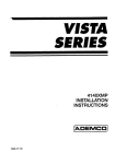
INSTALLATION AND MAINTENANCE
MODEL SOB RETARDERS
WITH
PNEUMATIC PILOT CHECK VALVES
(For Models Furnished After 6/1n9 x451016-5601)
'.,.
October, 1979
100104F/DN0034F
A-11/86-50-2337-2
PRINTED IN USA
UNION SWITCH &SIGNAL DIVISION
AMERICAN STANDARD INC I PITTSBURGH, PA 15237
~----------------------------------------------------SERVICE MANUAL 5796-B
INSTALLATION AND MAINTENANCE
MODEL 508 RETARDERS
WITH
PNEUMATIC PILOT CHECK VALVES
(For Models Furnished After 6/1ll9 x451016-5601)
October, 1979
100104F/ON0034F
A-11/86-50-2337-2
IINTEO IN USA
UNION SWITCH & SIGNAL DIVISION
AMERICAN STANDARD INC/ PITTSBURGH, PA 15237
SERVICE MANUAL
5796-B
INSTALLATION AND MAINTENANCE
MODEL SOB RETARDERS
WITH
PNEUMATIC PILOT CHECK VALVES
(For Models Furnished After 6/1!79 x451016-5601)
October, 1979
100104F/DN0034F
A-11/86-50-2337-2
PRINTED IN USA
UNION SWITCH & SIGNAL DIVISION
AMERICAN STANDARD INC I PITTSBURGH, PA 15237
UNION SWITCH a SIGNAL
TABLE OF CONTENTS
section
I
II
III
INTRODUCTION
2
DESCRIPTION AND OPERATION
2
INSTALLATION
5
3.1
5
5
~.?.
IV
v
VI
SPECIAL TOOLS
INSTALLATION PROCEDURES
MAINTEilANC~
7
4.1 OPERATIONAL PROBLEMS AND POSSIBLE CAUSES
7
4.2 ROUTINE MAINTENANCE
4.2.1 Hydraulic Fluid
4.2.2 Adjustment, Brake Shoe
4.2.3 Adjustment, Retarder
4.2.4 4-way Valves
4.2.5 General
8
8
8
8
9
9
SPECIAL TOOLS
37
5.1 LIST OF TOOLS
5.2 USE
37
37
PARTS LIST
37
APPENDAGE
40
5796-B, p. 1
m
ffi
UNION SWITCH & SIGNAL
SECTION I
INTRODUCTION
The Model 508 Air Assist car retarder has been developed by Union switch &
Signal to fulfill the need for an inexpensive, fast acting operable weight
responsive retarder capable of handling 160 ton cars.
SECTION II
DESCRIPTION AND OPERATION
The Model 508 retarder applies a braking force to car wheels that is directly
proportional to the weight of the car being retarded and, therefore, if all
other conditions are the same, removes approximately the same velocity head
from all cars irrespective of weight.
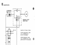
The basic retarder consists essentially of a retarder unit and a unitized
control system. The control system provides the means for operating the
retarder unit to the open or closed position to apply full retardation or no
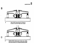
retardation as desired (see Figure 1).
The retarder unit comprises two steel lever arms that are tie mounted on
opposite sides of the running rail. The inner ends of the lever arms are
connected together by a through bolt that passes through the arms and a pair
of brackets that engage and support the running rail. The outer ends of the
lever arms are pivotally supported by the tie-mounted stool on one side and on
the other side by the piston of the hydraulic ram. Brake beams and shoes are
bolted to the lever arms on either side of the running rails.
stabilizer beams are provided within the retarder to maintain proper position
and gage of the running rail.
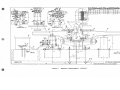
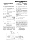
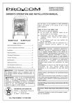
The control system of the Model 508 retarder is illustrated in Figure 2. This
system is hydraulically-actuated, pneumatically powered and electrically
controlled. A 4-way single solenoid pilot operated air valve, located in the
valve box, permits air to pass to the accumulator and the pilot check valve.
Pressure in the accumulator forces hydraulic fluid through the pneumatically
operated pilot check-valve into the ram, raising the ram to the normal closed
retarder position (see A, Figure 1).
When it is desired to release or open the retarder, the 4-way air valve
solenoid is energized (see Figure 2). This action exhausts air to atmosphere,
thus removing air pressure from the accumulator, and at the same applies air
pressure to the pilot check valve, opening a path to permit a return flow of
hydraulic fluid back into the accumulator. As the hydraulic fluid returns to
the accumulator, the ram is lowered to open the retarder (see c, Figure 1).
I.
5796-B, p. 2
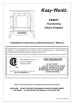
UNION SWITCH & SIGNAL
NORMAL POSITION. Retarder Closed-No Car Present. Ram
is extended to close retarder. Retarder rests on tie plate.
I
RETARDING POSITION. Retarder Closed-Car Present. Ram ls extended.
Brake shoes are spread by the car wheel, causing the retarder to rise from
the tie plate. The heavier the car, the greater the retarding force exerted.
C
OPEN POSITION. Retarder Open-Car Present. Hydraulic pressure is removed, the ram is
lowered, the outside brake shoe is withdrawn, and the retarder rests on the tie plate.
Figure 1. Model SOB Retarder Operation
5796-B, p. 3
m
UNION SWITCH & SIGNAL
ACCUMULATOR
'Si
I
I
L
p
_____
Air In
j
PNEUMATIC PILOT
CHECK VALVE
I
Operation of 4-Way Air Valve:
solenoid oeenergized, P Open
to A, B Exhaused via E.
Ram will be Extended.
Solenoid Energized, P Open
to B. A Exhaused via E. This
permits Ram will be Retracted.
Figure 2. Control Diagram
Table I.
Special Tools (X451016-0803)
Part Number
M451017-6501
J397056
N451017-6601
J397057
J397o'ss
J397058
5796-B, p. 4
Description
Gage, Brake shoe
wrench, Adjustable Spanner
Pump, Hydarulic Hand
Wrench, 3-1/2 Hex Box
wrench, Ratchet
socket, 3-1/2 Hex
UNION SWITCH & SIGNAL
SECTION III
INSTALLATION
3.1 SPECIAL TOOLS
Table I lists the special tools supplied with the Model SOB retarder. These
tools are required to perform the various functions described in the following
procedures.
3.2 INSTALLATION PROCEDURES
The following is a st,ep-by-step guide for the installation of a 5-lever Model
SOB Retarder. The retarder described is installed using 131 or 132 lb.
A.R.E.A. running rail. Installation of any other configuration of Model SOB
Retarder will be similar to the extent that viewing the appropriate general
drawing will make applicable modifications to this procedure readily apparent.
consider X451016-5601 a 5-lever Model SOB Retarder.
1.
Drill ties per C9457, Sheets 33 and 34, as needed (see •Tie
Schedule" for each application). Be sure to arrange for and
attach oak filler blocks as shown on Figure 5, section •A-A•.
Method used and parts to accomplish attachment of oak filler
block is to be supplied by customer.
2.
Affix retarder parts (rail support, item 5: base plate, item
85: and stool, item 25) to ties. see Figures 6, 7, 8 and 10.
3.
Later in this procedure, item 30 •bolt" and item 40 •2-1;4•
elastic stop nut•, Figures 6, 7, 8 and 10 will be put into
place. Now proceed per the following in preparation for that
time:
The 2-1/4" Elastic stop Nut will, of course, spin on easily up
to the point when the bolt engages with the nylon insert. To
avoid undue difficulty later, it is recommended that each
elastic stop nut be well greased and then screwed fully onto
some piece threaded 2-1/4" - 4-1/2• and removed prior to their
assembly in the retarder. Any handy bolt M451017-1102 can be
used for this purpose.
4.
Assemble manifolds per Figures S, View •y• or
or •E" and also Figures 6, 7, 8 and 10.
s.
Assemble brake shoes to brake beams (see Figure S, View
6.
Dig out or prepare roadbed such that top of retarder ties will
lie 16 inches below the desired level of the top of the
running rail, i.e., if retarder is being placed into existing
tracks, a hole 17' - 6" long by 14" wide and about 26" deep
(depth measured from top of existing running rail) need be
dug. (If existing ballast is not solid, dig down to a level
30• to 36• below top of running rail and back fill with
ballast of 1• minimum diameter to 26". level.
5796-B, p. 5
•z•).
•z•,
Detail •D•
•y•
or
UNION SWITCH & SIGNAL
7.
Attach accumulator/ram assembly N451388-2701 to Ram Mounting
Plate. see section •A-A•, Figures 6, 7, 8 and 10.
8.
Prepare running rail to lever bearing system as follows:
(a)
For each Figure 6 and 8 lever and tie assembly install
shims, item 145 as required per the tabulation for the
applicable rail size. (Note: Quantities of shims varies
with different rail sizes.) Retain shims in place with
washer, item 150 and nut, item 155.
NOTE
The brake shoe adjustment should be checked by gauges as
described in paragraph 4.2.2 of this manual before placing
the retarder into service. It may be necessary to add or
subtract shims at that time to achieve proper adjustment.
9.
Slip •sleeves• M451017-2206 into place in levers as needed. see
Figures 6, 7, 8 and 10. Oil or grease sleeves before inserting.
As manpower allows, Steps 2, 3, 4, 5, 6, 7, 8 and 9 can be completed
concurrently.
10. Lay ties as prepared in step 2 in place on 37-1/2• center.
Align rail supports so the centerline of the running rail will
be offset 9/16• from the centerline of the rail supports (see
Figure 5, Section •AA•).
11. Lay and attach valve box, tie strap and manifolds into place
on ties.
12. Now put levers as prepared in step 8 in place on the ties.
13. Apply an extreme pressure type, molybdenum disulfide grease to
each •washer• J475114-0101, see Figure 6, 7, 8 and 10, Item
35. Put •solt•, •washers• and •Elastic stop Nut• in place.
14. Put assembly as prepared in step 7 into place and attach to
lev.ers: Figure 6, 7, 8 and 10.
15. Attach brake beam assembly as prepared in Step 5 to levers.
see Figure 5, View •y• or •z•.
16. Lay running rails and guard rails and spike in place. See
Figure 5, for location of ties with respect to guard and
running rails before spiking.
NOTE
For 12 feet on either end of retarder, on retarder
side of track, drive spikes such that 112• - 3/4• gap
exists between rail and underside of spike head.
5796-B, p. 6
UNION SWITCH a SIGNAL
17. Make air connections between the manifolds and ram/accumulator
packages.
18. Install stabilizer beams (see Figure 5, Detail •B•).
insure that proper rail gauge is maintained.
Check to
19. Install rail anchors of appropriate size on the retarder side
of the track for a distance of approximately 25 feet on both
entry and leaving ends of the retarder.
20. Fill in additional ballast and tamp ties solidly, being
especially sure to have solid bed in the area under the
hydraulic rams and in the area under the stools.
21. As soon as the air and electrical inputs to the valve box are
connected, the retarder can be cycled to check out the
hydraulic and pneumatic syqte'.'lli;.
22. Adjust retarder for brake shoe clearance as outlined in
paragraphs 4.2.2 and 4.2.3.
23. Retarder is now ready for operation.
SECTION IV
MAINTENANCE
4.1 OPERATIONAL PROBLEMS AND POSSIBLE CAUSES
If retarder fails to remove rated velocity head, check the following items:
l.
One or more rams spongy in retard mode of operation.
a.
May need hydraulic fluid.
b.
Hydraulic system may contain entrapped air.
c.
May have defective pilot check valve.
2.
Check for incorrect brake shoe gap.
~.
Brake shoe may ~~ve qrease or paint build-up.
If lifting of a car wheel s~ou1A occur within the reta~ner, the following
points should be checked.
1.
Defective pilot check.valve.
2.
Brake shoe gap incorrect.
3.
Lifting is often caused by bad wheels -- if possible check lifting
wheel for heavy bead on tread edge, or broken flange.
5796-B, p. 7
UNION SWITCH 6 SIGNAL
4.2 ROUTINE MAINTENANCE
4.2.1
Hydraulic Fluid
To add hydraulic fluid to the hydraulic system, proceed as follows:
1.
Fully open retarder. This can be accomplished by pulling the levers
down, using a bar positioned between the running rail and brake shoe.
Pull levers down as far as possible (retarder must be opened such that
6• gap exists between brake shoes).
2.
connect oil transfer system (oil pump) into quick disconnect
connection. (Hydraulic system is supplied filled with Mobil Aero BFA
oil conforming to MIL-H-5606. Any oil put into a system must conform
to MIL-H-5606 and use of the Mobil Aero HFA is recommended.)
3.
carefully pump oil into hydraulic system until 15 psi back pressure is
detected, or until lever or hydraulic ram is seen to move at all,
whichever occurs first.
4.
Disconnect oil transfer system and replace dust cover.
NOTE
Make sure no air is pumped into system
in performing above operation.
4.2.2
Brake Shoe Adjustment
The Brake Shoes should be gauged 5• (+1/8 - 0) apart with 1-5/8• between the
gauge side of the running rail and the rubbing face of the inside brake shoe
when car is in the retarder. Adjustment for wear of brake shoes should be
made when the gap exceeds 5-1/4 •.•
4.2.3
1.
Retarder Adjustment
Insert five (5) retarder gauges into place in retarder, placing one at
each lever. Position gauge such that 1-5/8• wide leg fits between
gauge of rail and inside brake shoe.
NOTE
Make sure that in placing guage near retarder
section ends, that guage contacts shoe in that
area where shoe is straight.
2.
By adding or subtracting shims and adjusting bolt (M451017-1102),
bring retarder section brake shoes into contact with the gauge, making
sure that retarder is in •ready to retard• position.
3.
After completion of Step 12, remove gauges.
5796-B, p. 8
UNION SWITCH 6 SIGNAL
4.
After completion of Step 13, adjustment bolt (M451017-1102) should be
able to be rotated but have no end play. Check to make sure this is
true, tighten slightly if necessary.
5.
Open retarder using bar or piece of pipe and check to see that
retarder will open to 6• gap.
6.
Close retarder and recheck adjustment.
4.2.4
4-Way Air Valve (24V DC Operation)
Instructions for maintenance, parts, and other data pertinent to the 3/4•
4-way valves furnished with the Model SOB retarder (manufactured by Ross
Operating Valve company) are enclosed at the end of this manual. Parts for
these units should be ordered directly from the authorized distributor, making
certain the Part Numbers provided in this section are used, since some of the
parts are specially made for these unit. Distributor's address is as follows:
Pennsylvania Controls co., Inc.
250 Meadowland Blvd.
Washington, Pennsylvania 15301
4.2.5
1.
r
General
The retarder may be painted (the prime coated parts only) with a good
grade of weather resistant paint such as OA-1054 (Armstrong Paint and
Varnish Company).
CAUTION
Special care should be taken to prevent the
application of p·aint to the rubbing faces of
the brake shoes, as this will seriously reduce
the retarder effectiveness until the paint is
worn off.
2.
After 3 to 4 days of operation, the retarder should be reinspected.
Any misalignment should be corrected and all nuts and bolts given a
final tightening operation.
3.
Hydraulic system is initially filled with hydraulic fluid conforming
to MIL-H-5606 (Mobil Aero HFA is such a product): in replenishing or
refilling hydraulic system, a MIL-H-5606 type fluid must be used and
use of Mobil Aero HFA is highly recommended.
5796-B, p. 9/10
&,uSt!
Tl!nDN T 'TO SCH.. eot,IN•S..
.,,..77.fOH
OH.,..;_
m
-5
'"'Pl!
/IIPP'RO'll.. 60 UN.. fN,. PtR AS.SY.
~~Htl\f:::t:#,61J::'~~~: ~:e T~~t.ED
ON
ltOD OPC.NtN6.
£~t".t~~~:f7~~1:,.~~
& ~;ke:~:..-.OKDltA~:t ':ti~'! ~?5~
£
J79tTI1 CAN &£ 5\J&S"TITUTl<t> 1'1>11. N•SIUII• $IOI
"'
~!
t,Cll
lt:
"'
~
....:;
~
,r-,--
i--
---
I
L--
I
I
,i::(
•
M\
r-I
11rn 11 11 11
,
, , ,
tD , 11 ,
1
-t,,,,,A,.,-------~--l
I
I
1
I
I
"'
I
11~
,.
SYSTEM
Ftt.t.lNf
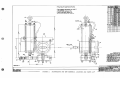
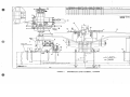
fl:J.f"'z3';~::f ':,3#11t ~~~ 11::lf,~u.:'":t.f;u,
1 ,r6W ''
1. fl1Zc~sr~$ ff/'f,,f"H~~?':s~"#..,
2. /IOtNIV£ EJiil1'lliV' 6"141¥.V Wfl.llE AND POIIJt OIL INTII TAPlll!J,
:.Jtf ?:'~,._ fl14/t'& il(ll!J6UI.$ A&.HIIN~E n, E~Pll..
,. = =
i "%,'JAYA~':i:f::(:.,,.,,. 1tmtc.--:
$..Ql¥N 4/JLEED«llt IMl.114 ON RU...llt
:J;e~t::f~
PCIMP
,tTTACH/llt.AIT:
our,,,..
.SPtLL.S
Bt.u:-,r
t!LOS£ /!ILIIIICDElt Mfur (';Mil' nLL•JJt Pf/HP ,,,,,,.,.A,eH'4!eN7:
8t.'OIVTINV£. lr>PUHP Jll'UOIJ INTO SdTIEH IJJNT'IL l'R&SSOIW
19UJN4 ~ , k l $11R£ TNm' lltNI IJtM$
9. SLOWLY CJtlVN 1!11..Z~OE"' fMU'I lf/llll S'11Et:"4L FIL.Ult ,.,,,,,,.
~
~d~t'iJ i:::?~
1o.
'X,~~J tf'&.vI'=r:£.~UU.
JI. INSPECT ANO TEST PER [U·t.372.
'3""°"
5.Jz
I
SIHIIM 1/1 - , . ~
DM/111-111.•
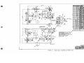
FIGURE 3.
ACCUMULATOR AND RAM ASSEMBLY, LOCATORS AND PARTS LIST
5796-B, p. 11/12
!ii n
~~~~~~~~~~~~~~~~~~-15J..#T$/t>~~·
. ,.
I.
,.
,.
z.
I.
,.,.
I.
JI.
3.
I!
,.
,.
N
~,I ~-. I
;~
'
z.
z.
z,.
:,_
I.
/.
~?Pr
.7
,.
,.
,.I.
z.
...
..
,,..
H
_,_
-~•
"'"'" IIDr. .,JIW.s,r.
IIT
-··
-~~
'"',.
z. ,,
,. ,,,
z.
z,
"
H
I.
z.
z.
-,.
_
-- ""'-' •-r
,n,
-_.,.
WASN-
__
....
..-r,r""G,«.Y..
-
·-,07
...
'-"'
»
:u
•.u..1-.,,PI!
m
.,.,,,.,
.
/.
~__)
•,.
,.
"·
....
JI
I.
z..
/..OOl<IN(i IN
()ll?£CT 01' ARRON
z.
,
A
/I
.ruo
,.
i!,_,U,.,
•ii
W"1'1.£~11~-"
Vl'NT/l.ATOI
cAP, ',,,,,,. r EC· 20)
,m•r
,
...., ,..u
.o~o
,.
i
I.
~lnFl//f
@ "'""'
IA1ll£O ON Ill.I.,.,_,
SI
52
,J;J
z.
,.
r,
~s
osz-
STUD
....
·~
-~.. ,
,,,,..;7.,
1,37S Z
,..,.. S7
11114
.wr.
WAINllr
1'4U4'
AflUQ,IIUSM
f.llldU
A.ATC.~
lrlVll'T, 1'11 it Y• lf'A N.IIA
urr1~11J1•-...,,...,,.
''Ak TIST
·-
/JOINf4(4•WAY) T~ltH.
NW
W,#SNr1
:s,c•- ,....,_.,z. ,111.. sr,
__... ...
.... ,..
,.,,,.
,,u.. ,,,
a•M
TIN (ilZtf)
TA& fNU)
et68
(
89!>0
,,.ft
.,
,00
Blot
-- "" ,.,.,,,,
-
,_
,,,.,. ••
z•
.,,
MO•
77,,._
T,'IPE. TEPLON
4N1/f IJIII UN>
,~
,,
¥Z
~ll'.ie,.,,1z N/Oc STt
04141a
",01Sl#J
P7SIM
7SS.O
-
-~ 7
..,II LL_ ........
-- ·- -r
rw,111'1
las•~
..
".,...
••
,. so
"'""
''""' ••
uur~UNOf/d
#I
u.
z.
z.
z.
-
••,.•• ,z
1:c•-,.,...u.. -Jti.csn..
...
""""
,.z. ..."' omz•IJ
,. •• ~4Z!I
,.,o,
u. ,_
,,.,
2.
,.
.n
.»
.. ..
V1EW ;1:1·
M
...... JI'_ _ . . . . , .
:~•«& .. *HZ~
..',. ..,. .,. ~,·. -,-,u-...
2.
1*U,,,ll#IIT
~
IA,0,0I
,_..
,-.a
~
4164,.%,j
.
'".
. _,.
__
- ..
H
,.
,_, I~ OIWIHI"
fi - ~
~
zz
sra..
- · ._.,,'- Ml'x.
7
'51!>#16
l#,.MIZ6 #Z 1111¥1..ls
,....
::$
M
~
,,
17
.,,
-7
.w,w-
2.
,.z
'!1'6. . %4
a/VE.It
v.fU'.c:,•• ......,,,
I#
:,_
l'!U,-
...........
'"'"
,-
......
.
II
IZ
v......
••.wttu.
I
,.
,.
,. •,.
z.
...,. "'
,.z.
,.
,.,.
L.EADS F(IRN.
WIT# A. V (IZ" t.tWt,)
,.
,.
,. ...z
z. •
,. •5
,.
,.
,.
,.
/.
..
·• -""·- - -..
...
-- -·....
m ..•
rs,,.,
---,,'ML. ,.__
,,,.
""'
:Ml
L"M
...0 ,,..
/IT
- ,-
TtllNrS . • # M ....... tltrlt#Nll'S
£•,usc,r1u:,,, ~ , . NII e,,11,rM./A~,. rN~IIIA#I
o,
,rc,.,s ~·@..
£,:.~~:;'!.o.r.,.,:::~~lfn,~N'II
£_"4!Nr
Mlt Jlllll'·?lll,,IJ·Z
AN.IIC<f'A 11-S,,t'J
JllkAr,,
c.,, Ml ,,,,,.SMl!r.
&,:.: ~::,.,~~ Ill SIINIU 11'1'*"'
A,__.... IIOw .,,"""""" ~~Sllllf'r swm:,v@)
0
:::j'D
/A. Wlt.W 80IC tllll'nl "ff'Ull~E
£ ~IN-Z..f.111111':..
€
~
/,.
_,
~
ITl,t@)
SWm:N@
' '
~
-
'''',_1 /
I
~
/
I
\_ TY'- ~ AtL PrP£
11:!i:)
CDNN£CTION5
•
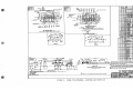
FIGURE 4.
VALVE BOX, LOCATORS AND PARTS LIST
5796-B, p. 13/14
(I
!t.
U••ll""
,....,-,-
ITP
lt11tf.•#lt11.11.1z,E•O
l>w&.
r•• £.
5TMl41Z£1t 811Nt
Awun~,,r
£NTl!Jf
~
l
'
IA,, SIU
.I
.
I
.l>
t,llillH,IJR"KE
lt4$IOl7-a50f
.l>
IJDIM Bii.ii-
I _I II
f/14510tl•G90J
"'4SIOf1...,._
D
D
9
M45tOl"!•lilllM
-SIOll~
"445IOll·0601
1)
Slloe,-..,..,.Kc ~ sr,.
I
6
7
I '"
I 4- I 4 I //
• I
l:S bc45IOl6-S711/
15
xn,.
AP,1.1a O
"•s.1--f_•J
}-
,-..A.
$ltS7
R4Sf0f,•
L.H.
/
D
J)
$MO& J!UIIAKC &..IL Sn.
"
:"/
;/
bus---
X4Sllll6·STOZ
Lcvca cNtt••- {L.H.J
LCY£A1,,, ..a ~ n r
R
"
R
R
'./
'
LI.VC"-,L.CJW-
&.E\IEA! IFNTllltlN6f/UI}
Z I 2 11.7
f'ott.&.CVt--..s J
Ll'vU.S
1-116
I
&,"...,
SMor.. ll•uu,r. uo. sn..
.Stt0r.. ll1U1..C ..... 5MOC 1'.••1t<C-sn-
' 12
3J3l14 IK•lllot•--
STA81~,z.~a
APf'I..IC.0 P£A.
OETl"IL.. 8""
I
"J>e.sc,.,,..,.,...
A+510t7-8ZOI
I
j
I
·11·
$1NLbn._~
I
I
~-
-
i+fi
$11.M
M$1
SEE tEVR /IN't.lc,lr111N --,.
l'(),lt lltnllTIOIIIIL
Pt/#11/6
UX451016·5~0Z
R.H. s LEVER MoocL soe, CAR REl"Ag,pe"
V1aw·2:
MS,
Y"'T
V,,,..-,- X4SIDl6· St.DI
S·Lirve:R. Moo1:1.. SOB CAR RETA IC.DE~
Y••1f~
v,~w')'•
l'UIN WIW 01' II« INTlt:lfltt:01/ITII: f LEA'I~ 1 /tNI I /l<l:Wtllt/1111/t 11551!/t SUES
i~
i;.
.F<,=;.-..-r--,~
....
-
4
4
4
14
::;:®
~ .
tl~-L~~P\j__Pl 1.,
,a
.....
w,··--·-·. - -
~~
T4'40"1S-OI01.
J-180267
Iv
V
l)ETAl&.""lf
=======
DETAIL"£•
=
'J
I
3
ll
3
,
D
I
1)
~ 51w. l>1M. 5MOwN ..-011 0 ..C.WONG OF l!>A .. ,<ING. SMor.$ 1$- 8-ltQUll,&D l"O"
T911Ctl
w..e&U. AMY OTMCa
&_ t0 .... x
'°"'·" ttl'"T.•O T1C.
T1E.$ ""'-
5CE L"YOuT•
& T",s
DE.TAil. -?,5N¥Jtwt.AP,LIC"TlON or ST"&tl.\'Z.C.A:. 8£AM
($cl\L&:• 1!1 ... ,: I f'r.)
(V IY#J~III U.. sfiill3 IMJl.••s•-•, o,,,. u,~u,..,4
<2' IYf. as7 111:o11 WASN6ft •"'11r1zz-11J,s-SNZ1•
SKOW\tllG. Lt.V£1l .ASSEM'&L"('
(2)
t'/4
l.lJUc w.11sN~
SQ IIIITS
&
(%) 1¥4 11111< NI/TS
FOR
Rl.(Wl,.f.D. T1U l>•1U.CD P&a. C94-5l•.$,..33
~CM&D1,11.. &S.
DIYr. .. ,s ,o .. A""'--v,...,,.
MoDt.1.. ~o-. CA• R&.TA"D&.k To 1H•A.1t.£..A. R\INN•HA ......._...._
F°"- ANY OTHltR Wl.tOHT RAI\..., HC.tGMT o, tr't~l..&a lt\,,,OC~ S M ~ 5 ' 1 C • Tllld' .,._. ~
RAU.. 15 ,·,T ~ £.LI.VATtOH A5' Rt.TAI\Dl.11. RtiNttrilNGi RA1L, WKLM NOC.Mt. tS , .. ~-~
£ UUA..D RAil. PE.A.A.R.E•.11. Pl.AM 504·.SS(TY..,CA..,,Tb a.. .,........
& F'o" Too.. s SI.It x ~s,ou.- 4805" (1:1)
KU) . . .
c .............
la7AnflC CA/l{llN}lfllN,t NIJ S·UYER_) _
~
'L.11.J-•SDa_s-uw,rJ -
I
(Sc A\.&.". I ~,... • ,,.,..)
t.,J IY,t FUIT INlfSHEJIJ
W 1'14
£Ya,,.._,...._
VAAIATION o• WM&&I.. T"tC""t.al ..,........_ III.01,1taC. AD..1Vl'fW!llbff' . .
,rou;s
Mi
TJ£5 TO •• PlflUEO 111 ellSTdrl£11 IN r,n.o. ( - 1 1 1 - )
-
r,,w
~
IJWf. ,,,. Ho-. Sift
CAR li'l!7Mllllt
[lt£Plftll)UUD , _ Fff/(116•g_4s;
:45/0/6 l5h
FIGURE 5.
MODEL SOB RETARDER, LOCATORS AND PARTS LIST
5796-B, p. 15/16
UNION SWITCH & SIGNAL
m
PARTS LI.ST
for:
Entering Lever As.sem.bly
5796-B, p. 17
UNION SWITCH & SIGNAL
SU Jl'F IJI.
:,C:Q ....
I
4 %
I
-
,so
V3'47??"
US ~'13IISl4Z
Z -
i£O 1411.III · ZlflZ
4 -
l65,,TSO!JZ4
~.f
~ ~ ln>•
CP
ELLI .-. .. ,o•
~r
•r111,r
-oa.T
I
'
&JR,451318-0,01
:.s
2
Ul'47Jiit 14•0101
I
,S
.,,,
IJ.T4ll01118
v
I
1'!.iUIM /?.N. IJ'tAKC
I
I
4S
'N4Sl611· Z10J
If
I
I
z
So 111~-e/lH
2
S5 UM45fC17·UC7
£-:> V:T4H,2.S
6S U.141-3150
"'O ul'l451c,,-2zoc;
75 u;r<."'7742
i!JEIM'l,~·H• 811il'tKE
TE f: 'If.,."'+ • .t::, ftll 6A&.II
Y4"01S" Of
/Jo,r. ~a .... 3YL
2 2
~·C•N"''I": )a., #£11.
I
PIPE .J/4
,,,
-
a
I
31
PIPE,J/4t•4~
I
I
Cii .... LV
4 4
-
•
•
.
".
"•
.
' •
4
I
4
$1/IIPOJtT VALYE
L
I
,
, ''
6AL ...
lllltP~!'f"'/4 !$ ~LV
P1PI. 314 • J6 a,.I: C.ALV
J
I
2 2
IB0.1t VA'""''
D
~J
l1.1•1te.a.'T
•a.11.,.
I
,1J11E.l'l"••J1~ ~AlV
I
--+-,-- -
l
I
I
I•
I
... J'sr;;.+os
UM4Sl017•UOI
:.; IJ:147503
"L,34776!!/
IOS 1,,:TS0095
,,c:.
UM
'!Jt!lt.877
,5 lt.J,.,l!JS40'-
"
I I
II
4
"
4
I I
If
4
"
1,4.o VJ48Z2S
I
I
SEE OT,..£1:t TA
I
e
I
..,
I
41 • 1$0 UM73"""(,
I
'II•
z.z
l>
J)
.
!!iiPA.;.~ •
CO'T'1'&a Ya $T1...
'I)
:.;
11\ULATOll A,,- 11-.c·~
%>
,:, UN4SI017·780Z
.,
"'"T zY+a:... .sT ...
»
e.:, u:r-c29
BS <,M4S 1017·770/
!a lvJ4B02.lo
IJ.S VJ-4 7772
II
\
STOOL
.D
I
z
·--I
LI.VILA.
l>
I
I
$HOE J>.»/fi,cl£ ~.,.;.
610375 2
•10919
-Ep-'
- ".°")1
, ,
1..avr.•
F
UR4Sl011·0810
;;o UM451011· I IOl
I
.$ND£,../JltRK£ //i.H •
$PIK~ 1/4,t · ~ $T1..
I\
F
VR.-4S"l3B8- OIDI
I
I
D
e,o,,, ,s
I
s
::;,
J:)
J;)
~.as u.:r .s~ozs 1
~ - --.-~
5£f. OTH£.R ,-.,...
-~
SUPPOR?; PIP£
Eu• .., flf<.v.
v.,,,,._,,1J11-o,02
5
SC~EW.( \•ti $n lM (4,f,.V)
Pt.V4 -4-, PIPE
F',rr,uc 45~ Y, •U
1 1 1 ;_7$IV7.3!!/IZ.r.
:?:J
l>llSC:lllPTION
I
l'l'Pl!:"'+•7'» 411.o.
//j
'
•"" JO!JZ41'3
;05 I.IM4510f7·(i50
.;.1 o UNl4S!Dt7•61(;3
115
.A\
J)w(o• .$H.
I
C~
1119IS#&•,~3T4 LIIC
l10t1,
'!' No. AIIIT Nv-,&llR
It\
Hl/£Jll U,,.
55 U;f48133
u;:r33517
:i:,
W11$Hltll 1/.t.,$T... LJo..
CP
13SDO
110&5 201. WA$HI.R C. :Z
.....,.
....,
WA5NLR,~STL
1WT~50$TL,CP
&.II;
C.,.
WAS"f.•
I•• ,cf. ~.10-"737
I
I
I
IC
414
07$
, - ,es
I
I
I
-
,-+-_._+-,..-;.. : t ·: 3
VJ3232S3
;r
11zs11
t9D M 327551>
ru .,,. M.r
IJ/0919
"'lk.11.
15 ,.,Pl.-"• .,. "-ALt'
1 ~S V.T3Z480
Eu..lll• ~.90°M,l.GoA•"· ST•
..!.'..j.'!:2.:!D~O:j.!:V:T~7:.:,.S~2~7!.;5~·D,::1:,'3~,::V_.j.--4.!ll::O:::S::•~,;:.s""•~A::;11l~t~
l.f.!.
,, _•• .:,'-::""::,:•L..j
l
,
I
i
I
t
zos
c:,c
........ II
MOU
ICIOOI.J
Nl#tL.., •J'll. dA,Y.
I
!
I'
/
/
/., /
_/
,
I
I
I 4 4-
2«4o vJ·,ofJOZ•
.If.
c:,.c1""'""°.,""
l)lt•11c
"IY"'ll
~roR "ART NVl18IIU or ITlMS MARKtD&,slt Gf.N. ow, P.fSJ(Jlf,·41/.M, .,,
S"Oll'AI roR OP!lwJNC, or D'!.11111 S#Ol 1$ RlOiJ1IJtD rON S)1,.T0 S1. WH!lL THtClfNE.JS.
'
/
1 i
,
AIR
,,··~o,a\
11,175130
VJlll4JS9,Z·f}IJ
//
/
.,
tnr~in
fr/tf"i.'r1~T::.~:t"r:~:~o~T~1~, ~";' ~,. T~;c;:~ 5.:,.;·~~,.~A',1v~:~l A:-::!':~1~'T f,~
SN/MS.
I
I
I
I
I
I
~~~~~--~~-.-~~~--.-~-~~~~~~~~~~~~~~-l-
.E.E
·-.., ,,.... · · ~
___
-·
...
boo:"'.::.:-1'-·
v1rwF
SEE VIEW
l
."!.c.·.:-:..1··..,
5796-B, p. 18
1-1
.-:-:.,·
.....,
uj
•,.l
JN
l•·•I
.--·
..
•
m
J?Au..
~?ORT
D.S.51017
RAi1. 9,r4
ISH
""Sla<1·9Hl(H
1,... I ..
8t<T
5M
IIWl513&8·D30t(OS
Ri!MAR1<S
I
l!I
II
$11..
t-~-t-~-+~-+~-t-~t-~~-+--f~-t---f~~~---11---1-~-f-~--f~-----·-t---l
I
·--i
I ~
.!i.l~ l'J! ..~
. -· , , I
....
I
11
'I
11~
J:;;
---1,.
jl· ·]t,"1t:-..!
t
•I Ar EA1TE.R1AJG, E11,1o(IR£C'O""
~
ZNIIUfll!lf
-t ~'MnfS7·SM
,:......J
- ___» :.J.
v,cw·e·
.L-.--.. '-'"·-:"·,. .·"·J.~. . .
E:frER,'::'t:,::'l~tl-,tzn,•Jn}
.SEc r10N
VtE"W
.
·A-A"
r
:,,.,r;!:;; =:a O
: :
"-t..-SE:CTION
s--;
jt! 1
r ..
c-c·
~AT EA1TER,.,t>£,vo(1R,r,:;"D)
1-r!,
ltli. /1'/PINf Llftl/lVT AT
l!NT£11Nf END (SCIIU•I\Nl•,n)
"·v ·"'·v"-)
(fDlt uro.rJ
IT(nS CAI.I.LO FOii
I I
-1......:..J,
.A.
--1~-,
~
••
-~-.
f~, .,;-~r~~- ~L?
" .... .,
.,,
,,
•
- -----t-1-t·_::rrn
I I
I
1'
l
•
•
I
l
I
z,
REPRODflCED FRO~
R4St0/6. SH
:;-..:,=
..,,
~.)
',r- -~~~;,:,~~==~!
I
>>
/<
i /
•<(<
) .)
.
'(
,.
~
_
~~~!~==~~~~'.'.'.'.~~~-'=~~::':~~~~~~~~~~~~~~~~~
=ffi'.::~:::::1~:±±=~L_l]J_Jf:tb
~~
.il...!~Tr-JI ;It• I ~
-
'
,,
r·
,• . ::.I
::
. \
I .L·
I. ·--~I
7,
('
~
"~.;~L-t,~+.f-- .. _ ... ....._
.
,
'J<lj
•
:
I
I
I
I
-~---/ )
•
L-
I
I
I
l
II
,,;
c·
(o
•--l
1
I
I II
I
,.
.• ,_._,
I!
It
I:
</
- . --···· -
-
.__ .,,.
l
L·
~
:====--------
60~ _ _ _ _
FIGURE 6.
/!J l
8
.,,.
'-.::."
=
I
_JI,:
I
.J
•
"
l .
====~~=====--_j~----·· \ ~
:1:
:I
:,I'
:
I
:
I
;-r.--==::::t:==:::::~:2--..
:
I
•fr
--
::
-
4.§
4~
!, .:I
·----· --------------------!
~
TtE
<.>
(IIH)
#:.77 °"-77A
C9457-5H.33
<..)
(~
<.'
>
I
'>
<"
l"'
<..'
_______ ___>
:
I
R.H. ASS£ MBL '(
L.H-
7
{UI)
>
( SHOWN)
Fl)lt
fl5SE:N13L'( ( OPPOSITE...)
l'LIJN W/£W OF
FOfi'
1'11/.IIE
Illa. & ,,_
PLAAI VIEW 111' VA<l'E
8or•-
LEVER FOR. E"4TE.RtNG E.tJo OF CAR. RETARDER
ENTERING LEVER ASSEMBLY, LOCATORS
5796-B, p. 19/20
UNION SWITCH & SIGNAL
m
PARTS LIST
for:
Intermediate Lever Assembly
5796-B, p. 21
UNION SWITCH & SIGNAL
111111'1
ITl.11111
_
Ne
2
ZiS
A>RT N......... l)wG.
s,,.
u:r 500""
No. Flou N.iMatt• J)w~.
::V1tSC:A.1PTION
I
i.SUlk~•JHlX CAP Cl'
S
.s...
l)f.SCIUPTt0>4
5{£ OTHER TAB
1!5 5
10
t70
17.S
I
300 u3.53oz,.,
5 111'1 %10 Z.36
rE;.~
315 UWl451017·0o01
"'S
'fll""9,•-'fa
PtPIE ...,,_" 3/
Rlt>SIS 4
-1H()I
;&
.SERv,a
G .. ,v.
D-AK•
JUAIVI "'·"'· · -......
3J.0
""
Ln.
Jil,:A"" • .M• a11 .. -.&
330
/I',
51JPPOOIT' T1£. $Tit.AP
20 LUI OTHER 1AIS
t
I
1
2.S' Ul!4SI017·0lft
30 U,14Sl017·flCZ
;,5 U.47.5114•0101
I
.. .,
J
<it
I
I
£.
FoR ~AIL SECTION SEE Dwc..
IS SEC DTHIH TAI!
'
,.
F
l)
:ao...,T
v
WA•Mf.ll
NUT • .,... , ... s,. ...
W" ATftllhl-A-·v
11
JI
i::
o
7
,
711
U"'4!1101'1·220li
'»
UJ'4"7742.
&O l.l:T48C2~
9927-Su. 238
I',..
!ol:.p,-,.---
C:onw.• 'I• $T ...
......,. .......................61.•
£ 5 UJ"4GtlltJO
I.
ST001,..
11,
lJ.1'480186
S IV/lf4SI.J,8·Z101
$0 t,1,(S',417·ZI/H
L&~a
L&V&-.
t)
%>
«:1,f.f.Vf.
WA1Ml.a.~&.IT"1., l.k
C.P
hi.IT '7/&HI.Jl $Tt..
c:•
p...........s ..
P........ R•WI MTG
SPll<f. ...... (o.,,.!1',(..
Wll&M&R
11\o,.
BOU 204 WA:SHi.R
C.Z.
;p
,. ,os
!
•
~
--.-
-,
-
~
-
~
- -·
-- ,-..,...
.
r
-
-
I
I
I I
I
'
1'
I
~
I
I
r- - '
-
----
I'
'!
1,
I
-
I'
I
~ I
r~ ~
I'
I'~
j
I
.--///
/
I
/
I
I
i
~
IZO Uf131J&.877
;
4
;3c
4
4f
,,5 VJ47772
14 D IJJ.f.llZ2!!J
I
'
I
II
F
VN/0111 ,Ii /fZ &Atv ,.,,.,
185
I
/90
f~~
I
I
• 'I'
' .['
I
I-'"
'
fn.rn•
'
'
O:
U:f7523C
1115<=
;:,:,s ll:T75Z7S·OIOJ
z,.,
V
IIOSI. .... ''"' I
zr .to,o/fl
uo
'
I'
//////.,.,/////
CP
WA5H£"t~51L Lii CP
NVT.l.t,,_$0 STL CP
I
I
F
NUT~ HEll Sri
vJ..it11020
'
L -
l
F
~
I
110 1,.74-,7~9
'
·I I"
"·
I'.
I'
'
'
~~
['·~
I'
5 796-B, p. 22
~
-EB
I
V:T47.50ll
flJIIIIT N11"DCRS
o,
IT[MS '1AlfHtD&_, SC[ t:lH
eS•
o,n
1:1,. DTHL" rARIAJ'IOH or WHUJ.
'I
//,'///
~AU
owe
,,s,01•·
$11 ff, a7C,:
o, 8irAlfl SHOI IS 1tlGUl1'tD rQlf, Jl'6 n> .s% #Hlll T•lttlNUJ~ A#1'
TtOCl!.NlSS w,u. 1rtou1111 AOJUSTlflNT or SHIMS.
f'MT.(lf/A.l SHOlt" ON THIS owe CAN DC .A,.,L,CD 10 eD1H IIM I. 4 H CAii •.1rA,rouu.
SNOWN roll o,LNIHr;
m
,;EN OW<;.
RE..NARK.S
F,45IOIG
Sw.56
fe
Sl!E LIIYIJQ1" -
Prl'IN# FDR RH. CAI NTA/ttJICP
~n=e ~ is PIPIN+ FU L.H. ~All NTM04'lt
OTHER PIPIN6
(,OR lftFONL Y')
ITEMS C,I\LL£.D FOR
ON t;EN owe;..
urc nAR,cfoO
1T£NJ
SECTION -c-C
//OLE..-)(•
i It
I
..c·
!.!."'\
~
./
r
.
I
'-.:......._ '."\
.'
I
I
i
'f'Oi
!:?''
,-r~
i
:1:
;I:
I
·--
I
---
I
ii
I
.
qh·'
L
6
L _ · _ ---- _--·-L
A
'I'
I
I
I
I
'B"
I
II
-33,~ RAn.wcnau~As
sHow•Cw•tH-1tAn11ASSEno,1;0 n,
-----,--.i+'--,-
60~
;J;, [
f
c°I;!;.;_":sH.33
ltH ,.,,, •11s
se::ND L":.~u.·l:A
13
:~:I . .
I
I
t
.,
I
32 ~
,,....
----- -------
l
J
I
I I
I
I
I ,
,I
.
I
DFP4IL
,I I
•ou·x;TH,s om-~,~
A'El'RODIJC£D FRIJH /JW(i.
ffll-,.
.
6f~--..,
I •
co -
.J!
4~
,J
ii,'
I
J: : (/ .
I
I f
I
5
\.
li'4SIOJ6 ·Sil Z6
0/: P111,, SuPPClt T
"fl-
~
~
I JL.
L· l:--I
Itf
'I
J
'
I
4§
(
1
)
">
,
<.
<.>
>
<.."
____ _>
'-'F'
FIGURE 7.
INTERMEDIATE LEVER ASSEM13L~, LOCATORS
5796-B, p. 23/24
UNION SWITCH & SIGNAL
PARTS LIST
for:
Leaving End Lever Assembly
5796-B, p. 25
UNION SWITCH & SIGNAL
!SC/
IX
Ft><
1-m•
IITit~
-
No
2
A>RT Nw .. 91tll l)wG.
s.,.
~£SCA.1PT10N
No. Al11T NwMMA. llwG: ~-
2to5 U:7 ,00.5.,
5
I
J:)
~EtCl1Hllf.TA~
• .... .,IIT
aa,i.
I
2.80
t--+--+--+-f--f--f--f--l--~l::a:;;?R~5.j--~~~~~t--~-+~+-~~~~~~~......Jll--+-...--l--1--+-4--1~~2....j.-,-J-+~~£~C~ln~H-£~R~7.~~~-,..J.-~,,-..f.--+.,,,,-IM:--K-&~T-R~a·,•-~------..,--&---i
1102.90 11'10S'9Z·#JS
• =95 VM3!J5.3fl•otl/
'100 U7.5l0257
--~- ,,
600S!I
3
P11t•
.SI~ Ji(
t6., GA.1.v.
Pllll.i.t..•J•~ &ALV
,os
I
310
•
•S
Ull-1513118-0201
Z O UP.-451386'-0IOZ
.•
•s
F
LCV&II
F
L&~-
"'1.fSIMIJ· z,01
"'--11~-...
So IIIUJOl7·Z~
55 UM4510n·~u.
z 60 UJ'4&1i,Z.~
2
I
,,.
I
2
I
I
i
I
'
,o
'I
,....
,...
..... ,z,;
8
I
I•!)
:
U.14"17G9
,5 ..:rsoo91
IJ"IJ8to877
'
,,o
,,s vJOH?37
:
t-'
~I.I.VI.
~s
I
I
.,.,.. . . 1 4 ~.....
UJ'4fol1JO
7t:J Ulll4510t,•220G
75 UJ'4"1742
9i, U:7411029
U"14!\101'1·77DI
UN451017·780/
5'5 VJ' 5G;40.9
11,0 UM4!>101'1•UOI
,os IJ:747.SOI
I
I ;
I
°!C,I
•'S
I
I
I
I
I''-
I
I
I
I
•l!fo
I
JIJIJ
'
•fO
I
·2 ,~; IUJ'.!1241!0
I
I
I
i
I'.
zoo
I
I
I
[,.
·~
-·~
'
'
I
I
226
t30
I
z ~: s
FH
!
/
/
/////////////
UM41', I011•Z804
D
25()
255
i
/
o,,, 1
HIIU'. Jloo 111/t I ZI*
II
zzo
I
I
111,g,,.J
UJ'75230
'ZOS VJ7S/l?S• tN03
.:10
2•0
//////
2&04
£ N I lftlT Nlllllllll.1 Ill' ITllfJ /'IMlrn/o.,Ut Pl# IJWf '41,111,·S1t•11t
.& f>Dtlf Slt#WAI 'Ill
.IIMI . , _ 1$
=6:v:,:>,;:::::=:::· :,.="::":::',.,
£
Cl4lW IJI A,,,,l.l~D ftJ
lt•TAIIHllS
#'FNIAII, 0,
/W(IVIJtrJI
111.l /lfAT'I. SHOt,/N OAI n,,1 .......
AH 6 L.H ~Alf
.
/'!' t3i-
..
....
. . .. ·....:: ··-·-·:..:..-;:
.•.
··. ---.....
-· - -..
--
-:::·::..·:: -::·=·· . . ~.._
; ~=--:.:. .:_ -:~. ·..:..
5796-B, p. 26
AA'£A
'
Jf4!l10H,11• 5901
-··-••
-.,•-•
.
Ll"""'11M6
......
aNOLEVf• A•lt1. troft flONL ! I O ~
•w::-,'°"'
•
8,rH
I
-3'-'""• .. .,. .. •ia.n
- - ....c•c--
APPI.ICl"T'ION
... ........
MODCL
-.
~
----··...
5o
._.
,0,
CAR RlrTAtDKR
ffi
R«M .....,CS
r
roll .REF ONL
IT£MS
CALLE..0 FOlt
fr'*:.. N~sE ZR,: 0 n~:«oO
~r~=-,q
c-c-
SEE Ulrlllll AffJ
~
(a
PiPlllf. RJN
e.H.
l O PIPING Ftllt t. H.
CAil llErMl>~ll.
LAJt l.'E"f'NfDEI!
Ar L<.•WNG £NO (IM<i'D)
r
---·
(F'Oll llEF DNlV}
~--
,,-c
USED INICN Clfl ~C'114ff;,#e
HAS IIIJIIE THAii S IJlt NJ UVEtPS
($€1 R•S1t11•· Slt.61 FOR
·
. PiAN Vttwsl
-,'-----l
j
I
. I'
111
'1 j
t~ ~-·•
:B
•
;
:
;• '
I1
I
I
..
.
(
'I'
I
jI
~:
s,,,..,,.,,.
f
c""
TIES WHl!N
ltO"AlfDE~ NII$ l"IO#E 1NM
SOltlO
)
(Rll/
(LH)
TIE'#: 78£o"-#78.D
I
I
C9457-51-1.33
UllleS.
I
11,
I
I
,L•
L·A·
Sum'< r
"
,
(o -
11------,
13
J
------
-----
!
I
{
STD
$TH.
rtE:
TIE -.ti! 78
C94-57-SH. 33
l---4,~
-4--4k
()FR,tUL
')
/
'· >
<''>
<'
)
(
')>
---------R£PRODUC£D
FR0/11
Dltf$
R45IO/(, -SH, Z'J.
I
3 3!5
IG
,OM /.S A55EM
•
4
- - -v
--!3--------------------~
(
- --------!
ING END Ol'C"'R R.ETARDE.R Al..$0 USED 'FOR LEV&:R,ol:5 &:.~It) WHEN RET... RDER H"-5 MoRE. TMI\N F1V£ LEVE.RS
FIGURE 8.
LEAVING END LEVER ASSEMBLY, LOCATORS
5796-B, p. 27/28
UNION SWITCH & SIGNAL
m
PARTS LIST
for:
Lever #6 Assembly
5796-B, p. 29
UNION SWITCH & SIGNAL
1"
";" "11'1111
Tl.frtl
.t:o,
No
AIRT Nu...-tet:ll l)wG. ,Si,t.
%.':..
l>ESCA.lPTION
No. Fll"T 111..,.. ._. J),,,IG•
s
Su.eTMa•
nr.•
.s...
.>uca1PT10..i
a1o1••l'!t.•T
I)
aa,a.
12.ss
1••
170
--.c ... lT.8a.1
..... --IN&
il.7J;
a,s
I
I
IJ:TO;JZ41,D
15 U..651581•0,0/
U..451381·0/0Z
ZS UR451017·0M
Jo LIM4.Sl017•110l
35 UJ'67A 114•0101
lJJ"480186
<t5 U144Sl.5118•Z701
50 IUM451017•ZI04
SS UM451 Oll·Z,:07
60 U:1"46G.?.~
65 U.T41iill110
7/J UM45101'l·ZZOG
75 U:1"4'774Z
eo U:746029
l!IS lu"14SIOl'7•770/
~o vl4451017·780/
SIS 11:r5r»40S
100 V"MSI01'7•UOI
105 IJ:747/SOll
110 t.34'7769
I !S 1.1:rS009S
U"1•&'77
illM1'9<40G,
rJO :1"411024
IJS UJ"477'T2
/4/J U:74822.9
145 IJM45 IOJ7•U"'
I
310
2
31S
I
I
I
5\JPl'Ofl.T Tit. 5Tlt .. P
>so UJ 56409
J6D
SP,u ...., •lo'f2 .Sc.
/,\
3CS UM45101'l•J.llf
t)
V:T.JJD2S7
27!, l/JD.U:JJ/1
')7P
4
4
4
fl
"l
I
I I
l
I
I
'I
I iI
E;
4
QuA~. Pl.If. TIIS.
II
::~I
,
//
!
I
.....,.,.,.. ....,. .........
t)
C:P
c:•
Pi.•<t& •••&
Pi.""""""' M,-c;_
l)
,..,.,:;.•t• -·
SP11't.
Wll•M•a fllD,.
:l)
......._,
........
w11-1.• '"'"IT•,"'-·
C:.P
W/IIMP.1/Jt.~T... l.o.. C:.P
-,•gp,, 'h-.• 4 .w Mls.lT1,,t:..P
2 !!!.T,it>.lll.,,c14'llL
'°' " .......... c..r.
;p
NuT.lil.o. . ..tr.$n.
IIIIASH&a lll.t fn,,LK.
c•
NUT .at.a_~. . . . . . . .
.SNt~ VA
C:.P
4141 W•IH&R
14\IT V..1.L,M'-,
, .... ,c ....
!li/4M ..,,. -.:.
CP
1:,_ v~
nrr1Nf # .r. N•I
Mt1SI. ~4-4 P•v
IIN I"'-' .r,. l'l T» Jr
190
,u..i3241!10
195
i:,...
1,.,..,.,·~.fi•w. tit.
UJ" 7S'l75 ·0103 IV7S'l7J
2,0 'IJ)'Ol'SUO
i,,,....
I
2.•5
2.Z.0
,,.5
z.•o
.
01 Ho.s« .U.11f111. t21"'1...,a,
"
2~0
a us
/
:
I
I
I
;.,s
~
1
UM41,I01'7•Zlot.
I
HOii. .... II/If' I IS" UINf)
c'"'"'~'~ ..,,"c.
~
''
l's
f',
///,
/
/,
I
.'/,'
///
I
I
. :I;:
:
I I
I
I
I
11'
I
I I
11 1
I
I
I
I
•
F'- P•RT NUM~Lll5 OF" lTI.IIIII M~•IJ)
~5".D•M.,5-N F"- OPE"llt\111, Oft &&111!.&
Lb., IH Glll,'l>wa,.
$ - . II R&OU•"&l:1.-...
=
5~2: Tc 5.914 Wt4e..EL. TtUC.11,,N&.5$1 AM't' OTM&tl ~ I O t J o,
Wll"t&.ai.. TM•CK.Wl.&S Wu.... A&CDUtRI. At:IJUSTJtli.. N"f OP' 5"•M•.
I
I
1 1
Ii I
I
I
I
I
I
I it
~i~-,------r'" l-f
I ~ _,o \----,L!
'SE.CT10N
&
I
£ 1.: l*:1:•1;:,.,,S;'J'f;~l"(:!~_,
y~1:'::'CJ: ."II:¥""19•·)
I
1
13,·p· C~
I
---
- - - - - - - - ~ ---
....
... ·:~... ~ .•-.- ~-..,~-""-"'"t-,
,.,..=:::~~
.
.......
r.!:""'
-
··-·...
......·---··
_.
M
--------------
fF•
Al¥&11AT10A1
-,Ii~~...~· .- : " • ""'" ,.,.,.,
..,·.., . . ·•·•I~
-·... ---,"."-•:,.-•Ml
-~~ ... ! ·,,1
~
5796-B, p. 30
,-..,.'t..a '//& !!!.T...
-. ....T 7Alat;!b11u- .&o.•
l.!1:1,,t.t.'I&
WA$Mt.a.'l'&S,.i.. L1<.
:I)
l!lS IJ:TDJJ1'7
I
I
,
S.PA_...;..;..
1200
I
.,,
"
D
1)3'481-"'I
z
f':~
/
p,,.
,,s
I
L---~~A--
r--;
A,,,,. •. - ... ATea.At.a,i;a .....~.....
D
4 1?S v:rn1us~
4,T. 180 UA752c>4
II
'
~
"'""·-
170
~~/1 rf
I
.,
~w ___: l...~
1-~-1,_,
(JM7a...--ir:.
.
-OOL
/SS
,,o
UJ"33$17
z.
~
,,._
I
'I
'I
I'
,so
4
4
I I
I
----+~-i
r-.,. tI
-©-)
4
4
I
I I
I I
I
\
--
I r
I I
I
I I I
I
4
......
NUT • .,.. , ... $T ...
... ,,,,o...
------~---
--
~
B
4
L&ll&•
v
""
2
2
I
2
I
I
I
I
>/.,,,..!!y,.
804,c
3 <f4 UJ 480Z67
\.&VI."
F
D
]!.
'"
I
30S
.
,,.
-t
.. ....
·-·
l>w• ~,,
Mot.TL ISO CM llrr•z,cl/f
m
!
-..
-
•(,/OJ
,.,.._A I 7fa
l!ML
LllAIL SU,,,HT......
t...,....riSASEl-lll451017
ISM-
I
6
I .5
lu,t4,S,Ol1" ..., , ,,
-
/li!HIIIIKS
F .fSIO,.
I ,,.
Sit 5.
l
I
!
!
,vr~rr.·iT, ~ > -
I!~~,
r-
-~:=!
(Foll REt:.
0N<-y)0~
IT£#fllfS
CIHLE.0
...... O,I
ti1t:u.owc
llAC Pt.PE LAfl/Old R¥I
•6n, M ""Hnl lEVLlt
1I
\
Vll!WP·O"
tJ-ti~
I.Jil'fl'rNHAYNUM{ZND)
VMV£8fJIFoR•641V•lll.hEJt!
ijf
,:.
•
r=f, 1·11
;::::=·--
rk I• I•
~--c:.
~~L~;,::.;:;..f1M' 111WR
~
Y
™"' 1;•.,,.,,
(;;::::;;:
I'
11
r'\
>""?f'"
~
_L
,,..,
.........
....
1
·1(( :I iI
·1
,;
:
I (1
I
:
I I
.
l: l l
I
I
I I
I 11
..
tu
- ..Flt#Hlf
. •
PAltT
; ....,G .
• I
t.,,..11,.,. 5.,,.,.cttr
T
R,$~!::J.-'~. s.,.,3Z.}
?
I
~
Ac:tn,,;:-.t.l
IS
<
>
(LH)
I
I
I
,,,
I
I
II
I
:$l
/3
:i
''
4 i +-4§
I
r>40
~-j
g
FIGURE 9.
~l
I
ASSEMl!JLEQ
0
I
_J;
'B"~
r:.~
I
11 I
_JI·- -33~ 8~""~
'*
--~
Tll~. 18D OI? 78£
(RH)
c 94-5"1- 514.33
..
i- • ,
~=:==~~Au.. ,=:ss5:=Ho~w=,y=lw=NE.N~R"~:=:""::'s~A=~~SEM=~=~=====:
·
11'
-
•I,
I
I
JL ·- -__
fRIE.Ptt,OOUC£0
I
I
i i 11 i i !i "'
-
T
.h
t
~1 tV )\ :_ : , } ~;--.
·LL·
I
:1· i (/
I
_,;
(;>
<.
'>
<"
)
<
__,__ ____ __>
R.#.AssE;.,,8LY fsHow.,).
IJ
---32"
.
£.}-/. Fl SS EMBLY (iJPPOStrE)FlJll' -
l/ll!W"" I/Al.VI! /14lf ._,,_ SEE v,w"i'
EVER.,6 &.•II (vs«-o w,u,;,v RETARDER. H... s MoRE TtJ-
.
rive. LEVERS)_
LEVER #6 ASSEMBLY, LOCATORS
5796-B, p. 31/32
UNION SWITCH & SIGNAL
EfJ
PARTS LIST
for:
Intermediate Lever Assembly (with helper springs)
5796-B, p. 33
UNION SWITCH & SIGNAL
..,,,,.
·•HI
I Te""'
No. Fl,t.T N,;N1!>£R
l)wG,.
.5M.
1u••oRT
l'IAIL
10
"
L&v&.a
F
1,.1.V'&.....
..
STOOi.
i•o1..T
v
1-.......1---;,---+~-+,~~
WAIMILR
t<luT aY•t, ..sT,.
/,\
1 •-- M'" A'T',or,llA,Nl'I 1\411.4'¥
p,,..
rc:p,.c-c;o•naa '/~~I...
:1'o..T 7... ,.-C:.Y.f MIJl.!tn.6o.8
l.<1.&L'IIL
WAJMLa ·"' , ..... La. C.P
, ..T '7/p. ... £. ST..
CP
P.•T& a•a&
I
P._aT& RAWI MTC
'SP,K&. ..........,..
se..
"'"&"&• "••·
WI.-..;.& .. ,;;;.;;; .PL. C.P
W•St<U 11.t..ST,.~. CP
!f.e-.s.w 1/~-.•3.l.Hf:J.!,T&..CP
,IU0'3
l
11,.s ZIC
.s,,,-.. ........ , •• u...
w11,S·.-.-:. -.
HtJ'r. .. -
W111!1N6A
#£"
sr,,.c,-
"-s,-,.,•. ~I'
NV'1".JA...a..,1n.,I!,.
.
I I I
\
t-~ ~ -
I
I
I I (
---~.!.-
(INI/IN.-li. lU ~'V lt•I"
l.!ICf.lLV\l 'h•1l1< I ll&J1.5T1.
···c.:PR.1W6 CoM•-.. ••,o~
Ro1>.-SPR...U. R&T•"o411.
H0\1$tN6 IPAllilft.
r ~
r~ -
~
~
..i.~,., ...
-
&.\.L. ll/,. • IOo" Pl\. \.li,as'I, !Id'
ri
///
///
~
,,
////
''
'
/);lFot PART
"T7
i :!
f!/!
,) , ,
i.1
'I
&
,,,1
'w···'J
10 - - -
°EF5ECT1cr...:":B·e
.
wo:s
OP' ITCM.S
,..MKID
A,
aeR ••"'· 'IJWG.
!t;~H T.·~::H.:::E:1::::K"H::5 e:~~ :~;.tsIJF
tl~~~::,0,;.0•
WMtri. THIC.KMIS.S
WILL ll!OVIRt AOJ\ISTMSNT
£ ~~&.~;E-r:~T!w"f.;
~ /32• MEii
/IIIIL
1.____
-
_.
/
;: 1
,,- _/
5796-B, p. 34
l15
h
I ::
Lr
18 MOS I.. \/Ji A1til'111' l."!l.,C)
Nl'•E. "l4 Al/f 't1"40N•I
~
i,., .~, !!!
I
v
I-
I-
/
-·
°&01.T-,/1•9dSO.HD C P.
,,.,,.5,.1.a 7
_'C.tt
.$tZ£
X4St/Jlf, ·t.oo,
PART NO.J
6Ml"S.
ri..1"1~A:~'l,.::~J'
*"'~"- ... llrll,a,Jt
tld'lltl!Wa/14'7 U,,,lf lf&I,.,__
N$C:RIPTtON
m
..
i,5uA:nc
-6001
-.-J.....L..- -
)
.,.
CUIUt... SUA!OflT
~AIL
h«"-1 7ll, Lf> I
3
Sk
luHs,on·no, lt9
la..,tA;""
I 911.
~-
41--l>Wlli-
~
flEMAltltS
F4513&8
,,suaa·•l'OI
5£E LA YHT ,..,.,
DF U,,,J/11._ CAii
RET~Fl/llt
;.
OTIM#
@PIPINlj F/JH J!ll. eM RD"AJtlWlt'
{ (!}PIPIN. FtJl1 l-1<1 rif{' /UTAll"D.Clt'
PIPINlf
,I
L __ ...J •
...
t- -
-1 T
-
I I
1·
(FoR R£v. c.i~v)
>oR oiJ Gul.l>wG.
0
-,
l'T& h\~ CAu..W.0
I
',\ I I
~I
/
& ~ .L..---:-'
-"s ___ _.~E:C":_J_C.~N==C=-=C;;,"
r
!:!.!!...!!
,
:I
\
RVNtJ IU Gt
wt:f§:!!T H£Ui.HT BASE HEAD F "'-~I() I?
'
\.
,.
@
ii.
·•-----·~
f--:-rr-..,
II
II
t,..:
r
I -·~·
.
~r}-~,~ ~
,"'lit\
)o •
'....:;:
..._:_
I
...,
r
,! ·: 11 I I
,- ·r
l I I
,,••-
,- ,....t-'..C= -r-*' -i=-..:l)
'":I
ic:3'_ "f-~r~
I - - --·::'::1
,,IQ
~'
I
I
l
I
:n·f·!~REl'tto.PUCCD
. .\
l(·
r~'"'
,
>
I---
Bi-
C945 7- ,Su•.34-
'B"-_.J_
13~--:-------.!.--'-_~
l_A·
Ll.___i
----------
•
TiE *°7!7
I
I. {.I.
I
<
()J: PA•t. SvPPC.~T
OF .SPR•,-.;G, hc,;$tAJG
~
I
(
. t:
".!.
I
11,
II
,11
·1
p,,. -- ---
J
I
I
,I
4~
I
-t--
4i
/
'
·<.
(
, :;
.>.
)
<.
___>
0
-
L
/4.,
LE.VE.R. ,Llpp~1CRTION. ,q:;... ..SttOWN
L.H, LE.VE.R 19PPLICl9r1,p1J, Ol"Po-5,rE & "9s
~ -
Al,,r~D
SPRING HELPf._R
FIGURE 10.
INTERMEDIATE LEVER ASSEMBLY (with helper springs), LOCATORS
5796-B, p. 35/36
UNION SWITCH a SIGNAL
SECTION V
SPECIAL TOOLS
5.1 LIST OF TOOLS
The following tools are required for the disassembly and reassembly of the
exhaust valves for inspection and cleaning.
3/16• Hex Allen wrench (Long)
1/4• Hex Allen wrench (Long)
412 Waldes convertible Truarc Pliers
No special tools are required for routine maintenance of the valve.
5.2 USE
1.
The 3/16• Allen wrench is used to remove the pilot and solenoid
assembly from the valve body. It is also used to remove the end plug
from the valve body.
2.
The 1/4• Allen wrench is used to remove the adapter from the valve
body.
3.
The Truarc Pliers are used to remove the retaining ring holding the
insert assembly in the pilot and solenoid assembly.
SECTION VI
PARTS LIST
The parts list that follows is a tabulation of the assemblies and kits that
may be necessary to maintain this exhaust valve. This 3/4 inch, four-way
valve may be ordered as a complete unit from:
Union switch & signal
P.O. Box 420
Pittsburgh, PA 15230-0420
However, parts for this unit should be ordered directly from:
Pennsylvania controls co., Inc.
250 Meadowland Blvd.
Washington, Pennsylvania 15301
Make certain that the part numbers provided in this section are used, because
some parts are specially made for these units.
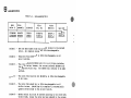
Individual parts for this valve are no longer available, but •kits• are
provided in lieu of individual parts. Table 6-1 shows the earliest version
(t2776B5941) to the current version (t2176A5909) which is underlined, and
projected horizontally is the appropriate sub-assembly or kit.
5796-B, p. 37
m
m
UNION SWITCH 6 SIGNAL
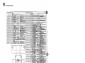
Table 6-1.
sub-Assembly/Kits
Ross
valve f
Pilot
Assembly
Solenoid
Pilot
Ser. Kit
valve
Body Kit
seal Kit
277685941
2176A5909
W744H79
W744H79
326F04
265804
643K87-A
643K87-A
265K77-J
265K77-J
508K87-K
263K77-K
column 1 -
Shows the Ross number from the earliest version to the current
version. All complete valves are 100% interchangeable.
column 2 -
The current Pilot iW744H79 is 100% interchangeable on all
earlier versions.
column 3 -
The earlier solenoid i326F04 will fit in all Pilots including
the current verion: however, the current Solenoid 1265804 fits
in the current Pilot only. The 326F04 will continue to be made
available.
column 4 -
The current Pilot service Kit t643K87-A is 100% interchangeable
in all Pi lots.
column 5 -
The current Valve Body Kit is 100% interchangeable in all
earlier versions. Installing this complete kit automatically
updates the valve body to the current version.
column 6 -
Gasket and seal Kits must be ordered according to the valve body
version number, unless the valve has been updated to the current
version by using the current valve Body Kit.
EXAMPLE
If you are working on 277685941 version that still incorporates the old parts, the appropriate seal Kit would be
508K87-K. If however, you are working on 277685941
version that incorporates the current Valve Body Kit
265K77-J, the appropriate seal Kit would be 263K77-K.
...
4,
5796-B, p. 38
I>
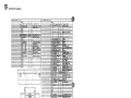
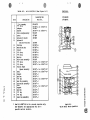
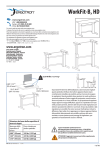
Table 6-2.
Item
1
2
3
4
6
11
12
12
13
14
15
16
17
18
50
61
62
64
_,
UI
'°I
O'I
0,
.
'tj
65
66
67
68
69
70
71
72
73
74
75
76
~
"'
Parts List/Kits (See Figure 6-1)
oescription
Pilot Assembly
•o• Ring
Adapter
Gasket
Valve Body Assembly
cover
solenoid (Latest)
solenoid
(Earlier Version)
cushion
Retaining Ring
Insert
•o• Ring
•o• Ring
Spring
Valve ~ody Assembly
•o• Ring
•o• Ring
Pinton Poppet
/Spacer Assembly
seal
Poppet
Spring
•o• Ring
End Plug Assembly
Piston/Rod Assembly
seal
Poppet
Spring
•o• Ring
•o• Ring
seat Plug Assembly
'
,/
VALVE NO.
Assembly/Kit
Part No.
2176A5909
277685941
W744H79
643K87-A or 263K77-K
222825
263K77-K Ot 265K77-J
992H78
457889
265804
326F04
643K87-A
643K87-A
643K87-A
643K87-A
643K87-A
643K87-A
992H78
265K77-J or 263K77-K*
265K77-J ot 263K77-K*
265K77-J
265K77-J
265K77-J
265K77-J
265K77-J
265K77-J
265K77-J
265K77-J
265K77-J
265K77-J
265K77-J
265K77-J
265K77-J
or 263K77-K*
or 263K77-K*
..... ...._,,
~
19
c::>
-
©---
([~~~~~~
~
-
~~
-@
-@
-00
or 263K77-K*
or 263K77-K*
c
z
z
·s
I
~
:I:
w
\0
* seal Kit 263K77-K is for current version on~y.
see Table 6-1 for appropriate kit for a
specific earlier version.
Pigure 6-1
Valve Repair Parts Location
••t5
z
>
r-
EB
ACS&
MAINTENANCE NOTES
I!~
D8TIIIDIT
FILTERS, LUBRICATORS AND VALVES
Supply Clean, lu&ricalfKI Air. An efficient filter and
lubricator should be installed in the line supplying air to
the equipment. The filter should be a unit that will remove
water and other contaminants in an air system. Accumulated liquid should be drained often from the filter. If a
portion of your system is in an area that does not. get
frequent routine maintenance, or if there is considerable
water in your air system, you should consider a filter
which drains itself automatically when its water level
reaches a given point. The lubricator used should deposit
oil in the system at low air flow rates as well as at high
air flow rates. Proper lubrication is achieved when all
moving parts in the air system are receiving enough oil
to maintain a thin coat of high grade lubrication. This is
necessary to insure long life for the equipment.
Following is a list of air line lubricants we have found
suitable:
1. Citco ......................... .
2. Esso .......................... .
...... Pacemaker #10
an SAE #10, or lighter, viscosity equivalent will prov
compatible with the Buna N sealing compounds used in
Ross Valves. Such oils should also atomize sufficiently in
most lubricators so to provide adequate lubrication of
the moving parts of an air system.
Normal Service. In most cases, it will not be necessary
to re1119ve the valve from its installation for servicing.
Normally, all that will need replacing are the seals and
possibly the springs. A periodic check of actuators and
locking devices for wear is recommended.
•
In Some Services Valves aequire Periodic Cleaning.
Under certain operating conditions, the valve ports and
the internal channels of the valve may build up a deposit
of varnish and /or foreign materials. Over a period of
time, these deposits will contribute to a sluggish action
and possibly a malfunction. It is suggested that a periodic
cleaning of valves be established should this condition
exist. (As to the cause of varnish, it sometimes results
from faulty rings in the air compressor which may allow
oil to get into the compression chamber. Heat in that
chamber can cause the oil's chemical breakdown.)
Rycon Industrial Oil #21
3. Mobil Oil Corp.
. ..... Almo #1
4. Mobil Oil Corp.
Vectra (Light)
5. Mobil Oil Corp.
DTE (Light)
6. Shell .............. .
Tellus #15
can cause irregularities in the electric power supply
which can cause solenoid bum-out.
· 7. Standard Oil Co.
American Industrial Oil #15
Moisture or Heat In Solenoid Enclosure. Under normal
8. Standard Oil Co.
American Industrial Oil #21
temperature and humidity conditions, a standard solenoid
should give no problems. Excessive moisture, condensation or heat in the solenoid enclosure can be harmful and
shorten coil life. Avoid subjecting standard solenoid
valves to such conditions. Should ambient temperature
exceed 120°F. or abnormally high humidity condition
exist, contact Ross for suitable solenoid coils.
9. Texaco
Regal Oil" A.R. & 0.
Generally speaking, any light bodied mineral or petroleum base oil with a 180°F. to 220°F. aniline point and
SOLENOIDS
ICHp lelay Confadl Clean. Dirty or pitted contacts
LITHO IN U,S,A,
II
'
ROSS OPERATING VALVE COMPANY
•
eaoooa RIYIHD •·71
DETROIT, MICHIGAN 48203
p. 40