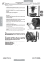
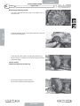
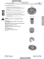
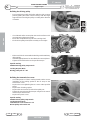
1
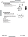
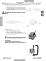
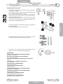
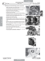
C
4 - STROKE ENGINE
2T
4T
PIAGGIO
ENGINE
MADISON 250 i.e. - Euro 3
WORKSHOP MANUALS
C - ENGINE
FOUR-STROKE ENGINE
Introduction
CHAPTER
C
TABLE OF CONTENTS
08.06
Pr
P
INTRODUCTION
1
1
4
MANUAL UPDATES
1
1.1
4
NOTES FOR EASY CONSULTATION
1
1.2
5
GENERAL WORK PROCEDURES
1
1.3
8
RECOMMENDATIONS
1
1.4
9
SPARK PLUGS
1
1.5
11
PIAGGIO ENGINE
2
2
13
ENGINE DISASSEMBLY
2
2.0
14
AUTOMATIC TRANSMISSION
2
2.1
14
FINAL REDUCTION
2
2.2
27
FLYWHEEL COVER
2
2.3
32
FLYWHEEL AND STARTING
2
2.4
34
CYLINDER ASSY AND TIMING SYSTEM
2
2.5
37
CRANKCASE - CRANKSHAFT
2
2.6
53
LUBRICATION
2
2.7
61
CRANKSHAFT OIL SEALS
2
2.8
63
OIL PUMP
2
2.9
65
ISSUE
ENGLISH
S
PAGE
SECTION 1
3
C - ENGINE
C
FOUR-STROKE ENGINE
CHAPTER
1
Introduction
INTRODUCTION
• All checks, maintenance, repairs or replacements, etc. on the vehicles manufactured by Malaguti are to be
performed by skilled and expert technical personnel with specific experience in state-of-the-art technology and
full knowledge of the quickest and most rational procedures, technical characteristics, setting values and tightening torques, which may only be properly and exhaustively provided by the manufacturer.
• This set of WORKSHOP MANUALS concerning four-stroke engines provides technicians of the sector (Authorised Service Centres, etc.), the essential information for operating in accordance with the latest good working practices and work safety regulations.
• These publications provide all necessary information for routine procedures on all the MALAGUTI motor vehicles
equipped with four-stroke engines currently in production at the date of issue. The information provided deals with
the motor vehicle ENGINES. Some basic technical information has been intentionally omitted as it is considered
to be common knowledge.
ENGLISH
• Additional information is available in the SPARE PARTS CATALOGUES of each model.
• It is important that before referring to the specific engine manual, the information given in this general section be
carefully read as it provides all the essential hints and guidelines for best consulting the various topics and main
technical subjects.
Note:
These manuals provide the necessary information and instructions for routine maintenance and servicing. This
information has been given to us by the engine manufacturers. We therefore decline all responsibility for any error,
omission or misrepresentation.
YAMAHA reserves the right to make any changes and modifications hereto it deems necessary without prior
notice.
For further information and details, please contact the MALAGUTI Service Division.
1.1
MANUAL UPDATES
• Updated pages of this publication will be delivered by us (in a reasonable time). The superseded sheets should
not be removed from the manual as they remain applicable to the servicing of pre-modified engines.
• The table of contents will be duly updated in the event that new pages are inserted, which render the consultation of the manual difficult.
• IMPORTANT! The Workshop Manuals are to be considered as essential tools to be properly kept up-to-date so
as to maintain their “validity” over time.
4
PAGE
SECTION 1
ISSUE
08.06
C - ENGINE
FOUR-STROKE ENGINE
Introduction
CHAPTER
C
1.2 NOTES FOR EASY CONSULTATION
PAGE LAYOUT
Chapter
X
Engine model
W
Page n°
Z
Date of issue
X
Y
ENGLISH
Y
Z
W
(RH PAGE)
MODIFIED PAGES
• Modified pages shall bear the same number as those in the previous edition/pre-modified ones, followed by the
letter M, with the date of issue appearing in the appropriate box.
• Modified pages may contain new illustrations; in this case, the added illustration (or illustrations) will bear the
number of the illustration on the former page, followed by a letter.
ADDITIONAL PAGES
• Any additional pages shall bear the last number of the section to which they belong, followed by the letter A and
the date of issue.
EDITING SYMBOLS
• Symbols have been provided for quick and easy reference (see page 6), identifying situations requiring utmost
attention or providing practical suggestions or simple information.
• These symbols may appear next to a text (in which case they refer solely to the text itself), next to a figure
(in which case they refer to the topic illustrated in the figure and to the relative text), or at the top of the page
(in which case they refer to all the topics dealt with in the page).
Note:
The meaning of the symbols should be duly memorised as their scope is to avoid having to repeat basic technical
concepts or safety recommendations. They are therefore to be considered as veritable “memory tags”. In case
of any doubt as to their meaning, consult the page in which they are fully described.
08.06
ISSUE
PAGE
SECTION 1
5
C - ENGINE
FOUR-STROKE ENGINE
C
CHAPTER
Introduction
EDITING SYMBOLS
A)
CAUTION! Recommendations and precautions regarding rider safety and motor vehicle integrity.
B)
WARNING!
Situations entailing the risk of personal injury to maintenance or repair mechanics, other workshop personnel
or third parties, or damage to environment, vehicle or
equipment.
C)
B
ENGLISH
FIRE HAZARD
Indicates operations which may constitute a fire hazard.
C
RISK OF EXPLOSION
Indicates operations which may constitute a risk of explosion.
D
E)
TOXIC FUMES
Indicates a possibility of intoxication or inflammation of
the upper respiratory tract.
E
F)
MECHANICAL MAINTENANCE
Operations to be performed only by an expert mechanic.
F
G)
ELECTRICAL MAINTENANCE
Operations be performed only by an expert electrical/
electronic technician.
G
H)
NO!
Operations to be absolutely avoided.
I)
ENGINE SERVICE MANUAL
Indicates information which may be obtained by referring to said manual.
I
SPARE PARTS CATALOGUE
Indicates information which may be obtained by referring to said catalogue.
L
D)
L)
6
A
PAGE
SECTION 1
H
M
R
ISSUE
08.06
C - ENGINE
FOUR-STROKE ENGINE
Introduction
CHAPTER
C
ABBREVIATIONS
F
Cs
P
Pr
S
Sc
T
V
Figure
Tightening torque
Page
Paragraph
Section
Diagram
Table
Screw
ENGLISH
Note:
the letter V in the illustrations refers to retaining or adjusting screws. The number following this letter refers to the
number of the same type of screw in the unit or component described and illustrated. Letters not followed by a
number indicate a single screw. In case of different screws being referred to in the illustration, the letter V is
followed by a number and a small letter, for instance: (V4a).
Unless otherwise specified, units and components are reassembled by proceeding in the reverse order of removal.
OPERATIONAL SYMBOLS
L)
LOCTITE
O)
Oil lubrication
G)
Greasing
08.06
ISSUE
L
O
G
PAGE
SECTION 1
7
C - ENGINE
C
FOUR-STROKE ENGINE
CHAPTER
1.3
Introduction
GENERAL WORK PROCEDURES
• The advice, recommendations and warnings given hereafter are aimed at ensuring maximum work safety as
well as at considerably reducing the risk of accidents, personal injury, equipment damage and idle times. They
should therefore be strictly adhered to.
ADVICE:
• Only use quality tools and equipment.
• Only use equipment conforming to EU Directives for lifting the vehicle.
• During operations, always keep tools and equipment at hand, possibly laying them out according to the sequence in which they are to be used. Absolutely avoid putting them on the vehicle itself, out-of-sight or in poorly
accessible places.
ENGLISH
• Always keep the work area clean and tidy.
• When tightening screws or nuts, start with the larger diameter or inner fasteners, and tighten them in progressive “pulls” in accordance to a “criss-cross” pattern.
• Preferably use open-end box wrenches by “pulling” and not “pushing”.
• Adjustable wrenches (F. 1) should only be used in case of emergency, i.e. when a properly sized wrench is not
available. They should preferably not be used as the movable jaw tends to open thus risking damaging or not
properly tightening the bolt to the correct torque. In any case, when using an adjustable wrench, take care to
proceed as shown in Figure 1.
• Except for occasional customers, always make out and deliver to the customer a work sheet specifying the
operations performed, with notes as to any future checks eventually required.
F. 1
8
PAGE
SECTION 1
ISSUE
08.06
C - ENGINE
FOUR-STROKE ENGINE
Introduction
1.4
CHAPTER
C
WARNINGS
• Before carrying out any operation on the vehicle, wait for all parts to cool down.
• For operations requiring two mechanics, make sure that the various steps to be performed by each of them are
clearly defined and coordinated beforehand.
• Make sure that each component has been properly fitted before proceeding with the next one.
• Lubricate all parts (where applicable) before reinstalling them.
• Gaskets, O-rings, circlips and split pins must be replaced at every refitting.
• The torque settings specified in the manuals refer to the “final torque”, which must be attained progressively by
steps.
ENGLISH
• Loosen and tighten aluminium alloy parts (covers) only after the engine has fully cooled down.
• Only use screwdrivers with sizes suitable to the screws to be loosened or tightened.
• Work in a comfortable position and ensure that the vehicle is stable.
• Never use a screwdriver as a lever or chisel.
• Never use pincers to loosen or tighten screws or nuts because, in addition to not providing a sufficient clamping
force, they may also damage the screw head or nut hexagon.
• Never tap the wrench with a hammer or other similar tools to loosen or tighten screws and nuts (F. 2).
• Never attempt to increase the lever arm by fitting a tube into the wrench (F. 3).
F. 2
08.06
ISSUE
F. 3
PAGE
SECTION 1
9
C - ENGINE
C
FOUR-STROKE ENGINE
Introduction
CHAPTER
Never use open flames for any reason.
Never leave open containers or containers not suitable for holding fuel in passageways, close to heat
sources, etc
Never use petrol to clean the vehicle or the floor of the workshop. Always use low flash point solvents to
clean the vehicle components.
Never suck from or blow into the fuel pipe.
When welding, make sure that there are no flammable liquids in the vicinity. Always remove the tank, even
if completely empty, and disconnect the negative cable (-) from the battery.
Never leave the engine running in closed or poorly ventilated areas.
ENGLISH
Before any servicing, make sure that the motorbike is perfectly stable.
The front wheel should preferably be anchored to the equipment (A - F 4) integral with the lifting board.
A
F. 4
10
PAGE
SECTION 1
ISSUE
08.06
C - ENGINE
FOUR-STROKE ENGINE
Introduction
CHAPTER
C
1.5 SPARK PLUGS
1
Insulator
2
Body
3
Gasket
4
5
6
Electrode
Earth electrode
Threads
ENGLISH
F. 5
SPARK PLUG MAINTENANCE
• Spark plug maintenance consists essentially of a periodical visual inspection. Remove the spark plug and check
for proper condition and gap.
• Clean the electrodes and the insulator thoroughly by means of a wire brush.
• Remove any residual dirt with a strong jet of compressed air.
• Lubricate spark plug thread with engine oil or graphitised grease, and install it by hand until finger tight.
Tighten to the specified torque with a spark plug wrench (see F.6).
It is imperative that any spark plug exhibiting cracks on the insulator or corroded electrodes be
replaced.
SPARK PLUG REPLACEMENT
20,000 km
• Upon prescribed mileage being reached, always replace the spark plug. Use YAMAHA recommended spark
plugs.
• When replacing exhausted spark plugs, visually inspect spark plug condition as described above to ascertain
whether or not the engine is running properly.
08.06
ISSUE
PAGE
SECTION 1
11
CHAPTER
SECTION 2
Piaggio Engine
WORKSHOP MANUALS
ISSUE 08.06
C
C - ENGINE
FOUR-STROKE ENGINE
C
CHAPTER
Piaggio Engine
2.0 ENGINE DISASSEMBLY
See Chapter A of “Chassis” manual
2.1 AUTOMATIC TRANSMISSION
Transmission cover
-
To remove the transmission cover it is necessary to remove
the plastic cover first, by inserting a screwdriver in the slotted
holes. Using the clutch bell lock wrench shown in the figure,
remove the driven pulley axle locking nut and washer.
Specific tooling
020423Y driven pulley stop wrench
ENGLISH
-
Remove the cap/dipstick from the engine oil filling hole.
Remove the ten screws.
Remove the transmission cover.
N.B.
WHEN YOU ARE REMOVING THE TRANSMISSION COVER
YOU MUST BE CAREFUL NOT TO DROP THE CLUTCH BELL.
Air duct
14
-
Remove the transmission compartment air intake cover shown
in the photograph.
-
Remove the five screws on two different levels as well as the
small casing.
PAGE
ISSUE
SECTION 2
08.06
C - ENGINE
FOUR-STROKE ENGINE
Piaggio Engine
CHAPTER
C
PAGE
15
Removing the driven pulley shaft bearing
-
Remove the clip from the inside of the cover.
Remove the bearing from the crankcase by means of:
Specific tooling
020376Y Handle for adaptors
020375Y Adapter 28 x 30 mm
020412Y 15 mm guide
Refitting the driven pulley shaft bearing
-
Slightly heat the crankcase from the inside so as not to damage
the painted surface.
Insert the bearing in its seat.
Refit the seeger ring.
ENGLISH
-
CAUTION
USE AN APPROPRIATE REST SURFACE TO AVOID
DAMAGING THE COVER PAINT.
N.B.
ALWAYS REPLACE THE BEARING WITH A NEW ONE UPON
REASSEMBLY.
Specific tooling
020376Y Handle for adaptors
020357Y 32 x 35 mm adaptor
020412Y 15 mm guide
08.06
ISSUE
SECTION 2
SECTION 3
C - ENGINE
FOUR-STROKE ENGINE
C
CHAPTER
Piaggio Engine
Baffle roller
-
-
Check that the roller does not show signs of wear and that it
turns freely.
Remove the special clamping screws as indicated in the
photograph
Check the outer diameter of the roller does not have defects
that could jeopardise belt functioning
For refitting, place the roller with the belt containment edge
on the engine crankcase side
Tighten the screw at the specified torque.
ENGLISH
Locking torques (N*m)
Anti-flapping roller 12 ÷ 16
Removing the driven pulley
-
Remove the clutch bell housing and the driven pulley assembly.
N.B.
THE UNIT CAN BE REMOVED EVEN WITH THE DRIVING
PULLEY FITTED.
Inspecting the clutch drum
-
Check that the clutch bell is not worn or damaged.
Measure the clutch bell inside diameter.
Characteristic
Max value clutch bell
Max value: Ø 134.5 mm
Clutch Bell Standard value
Standard value: Ø134 ÷ 134.2 mm
16
PAGE
ISSUE
SECTION 2
08.06
C - ENGINE
FOUR-STROKE ENGINE
Piaggio Engine
CHAPTER
C
PAGE
17
Checking the bell working surface eccentricity
-
-
Install the bell on a driven pulley shaft using 2 bearings (inner
diameter 15 and 17 mm).
Lock using the original spacer and nut.
Place the bell/shaft assembly on the support to check the
crankshaft alignment.
Using a feeler pin gauge and the magnetic base, measure the
bell eccentricity.
Repeat the measurement in 3 positions (central, internal,
external).
In case of anomalies, replace the bell.
ENGLISH
-
Specific tooling
020074Y Support base for checking crankshaft alignment
020335Y Magnetic stand for dial gauge
Specifications
Check clutch housing
Eccentricity threshold
Max. permissible eccentricity: 0,15 mm
Removing the clutch
Fit the special driven pulley spring compressor tool with medium
length pins in position “C” screwed up from the inner side of the
tool.
- Introduce adapter ring n° 11 with the chamfering facing the
inside of the tool.
- Fit the driven pulley assembly on the tool with the insertion of
the three pins in the ventilation holes in the earth holder
support.
- Make sure that the clutch is perfectly inserted into the adapter
ring before proceeding to loosen/tighten the clutch nut.
- Use the special 46x55 wrench component n°9 to remove the
nut fixing the clutch in place.
- Dismantle the driven pulley components (Clutch and spring
with its plastic holder)
CAUTION
THE TOOL MUST BE FIRMLY FIXED IN THE CLAMP AND
THE CENTRAL SCREW MUST BE BROUGHT INTO CONTACT
WITH THE TOOL. EXCESSIVE TORQUE CAN CAUSE THE
APPROPRIATE TOOL TO BUCKLE.
Specific tooling
020444Y011 Adapter ring
020444Y009 wrench 46 x 55
020444Y Driven pulley spring compressor fit/removal tool
08.06
ISSUE
SECTION 2
SECTION 3
C - ENGINE
FOUR-STROKE ENGINE
C
CHAPTER
Piaggio Engine
Inspecting the clutch
-
Check the thickness of the clutch mass friction material.
The masses must not show traces of lubricants; otherwise,
check the driven pulley unit seals.
N.B.
UPON RUNNING-IN, THE MASSES MUST EXHIBIT A
CENTRAL CONTACT SURFACE AND MUST NOT BE
DIFFERENT FROM ONE ANOTHER.
DIFFERENT CONDITIONS MAY CAUSE CLUTCH TEARING.
CAUTION
DO NOT OPEN THE MASSES USING TOOLS TO PREVENT A
VARIATION IN THE RETURN SPRING LOAD.
ENGLISH
Characteristic
Check minimum thickness 1 mm
Pin retaining collar
-
Simultaneously turn and pull the collar manually to remove it.
N.B.
USE TWO SCREWDRIVERS IF YOU HAVE DIFFICULTY.
N.B.
BE CAREFUL NOT TO PUSH THE SCREW DRIVERS IN TOO
FAR TO AVOID DAMAGE THAT COULD ENDANGER THE ORING SEAL.
-
18
Remove the four torque server pins and pull the half pulleys
apart.
PAGE
ISSUE
SECTION 2
08.06
C - ENGINE
FOUR-STROKE ENGINE
Piaggio Engine
CHAPTER
C
PAGE
19
Removing the driven half-pulley bearing
-
-
Check there are no signs of wear and/or noisiness;
Replace with a new one if there are.
Remove the retaining ring using two flat blade screwdrivers.
Support the pulley bushing adequately from the threaded side
using a wooden surface.
Using a hammer and pin, knock the ball bearing out as shown
in the figure.
Support the pulley properly using the bell as shown in the
figure.
ENGLISH
-
Specific tooling
001467Y035 Bearing housing external ø 47 mm
-
Remove the roller bearing using the modular punch.
Specific tooling
020376Y Handle for adaptors
020456Y Ø 24 mm adaptor
020363Y 20mm guide
Inspecting the driven fixed half-pulley
-
Version 250
Measure the outer diameter of the pulley bushing.
Check the contact surface with the belt to make sure there
are no flaws.
Check the riveted joints are functional.
Check the evenness of the belt contact surface.
Characteristic
Minimum half pulley diameter
Minimum admissible diameter Ø 40.96 mm
Standard half pulley diameter
Standard diameter Ø 40.985 mm
wear limit: 0.3 mm
08.06
ISSUE
SECTION 2
SECTION 3
C - ENGINE
FOUR-STROKE ENGINE
C
CHAPTER
Piaggio Engine
Inspecting the driven sliding half-pulley
-
Remove the two internal grommets and the two O-rings.
Measure the inner diameter of the mobile half-pulley’s central
bushing.
Check the contact surface with the belt to make sure there
are no flaws.
Check the riveted joints are functional.
Check the evenness of the belt contact surface.
MOBILE DRIVEN HALF PULLEY DIMENSIONS
ENGLISH
Specification
wear limit
standard diameter
maximum allowable diameter
Desc./Quantity
0.3 mm
Ø 41,000 ÷ 41,035 mm
Ø 41.08 mm
Refitting the driven half-pulley bearing
-
Support the pulley bushing adequately from the threaded side
using a wooden surface.
Fit a new roller sleeve as in the figure.
For the fitting of the new ball bearing, follow the example in
the picture using a modular punch.
Fit the retention ring
N.B.
Fit the ball bearing with the visible shield
Specific tooling
020376Y Handle for adaptors
020375Y Adapter 28 x 30 mm
020424Y Driven pulley roller casing fitting punch
20
PAGE
ISSUE
SECTION 2
08.06
C - ENGINE
FOUR-STROKE ENGINE
Piaggio Engine
CHAPTER
C
PAGE
21
Refitting the driven pulley
-
Insert the new oil guards and O-rings on the mobile half-pulley.
Lightly grease the O-rings O-R (A) shown in the figure.
Fit the half-pulley over the bushing using the appropriate tool
Check that the pins are not worn and proceed with the refitting
in the relative hollows.Refit the torque server closure collar.
Using a curved-spout grease gun, lubricate the driven pulley
assembly with approximately 6 gr of grease. Apply the grease
through one of the holes in the bushing until it comes out
through the hole on the opposite side. This operation is
necessary to avoid the presence of grease beyond the Orings.
ENGLISH
N.B.
THE TORQUE SERVER GREASING OPERATION CAN BE
DONE BOTH WITH BEARINGS FITTED AND WHEN THEY ARE
BEING REPLACED; UNDERTAKING THE OPERATION WHEN
THE BEARINGS ARE BEING SERVICED MIGHT BE EASIER.
Specific tooling
020263Y Driven pulley assembly sheath
Recommended products
TUTELA MRM 2 Grease for the rotating ring of the tone wheel
Molybdenum disulphide grease and lithium soap
Inspecting the clutch spring
-
Measure the length of the spring, while it is relaxed.
Characteristic
Standard length: 123 mm
Acceptable limit after use: 118 mm
08.06
ISSUE
SECTION 2
SECTION 3
C - ENGINE
FOUR-STROKE ENGINE
C
CHAPTER
Piaggio Engine
Refitting the clutch
-
ENGLISH
-
-
Support the driven pulley spring compressor appropriate tool
with the control screw in vertical axis.
Arrange the tool with the medium length pins screwed in
position «C» on the inside.
Introduce the adapter ring n° 11 with the chamfering facing
upwards.
Insert the clutch on the adapter ring.
Lubricate the end of the spring that abuts against the servosystem closing collar.
Insert the spring with relevant plastic holder in contact with
the clutch.
Insert the driving belt into the pulley unit according to their
direction of rotation.
Insert the pulley unit with the belt into the tool.
Slightly pre-load the spring.
Make sure that the clutch is perfectly inserted into the adapter
ring before proceeding to tighten the clutch nut.
Place the tool in the clamp with the control screw on the
horizontal axis.
Fully pre-load the spring.
Apply the clutch fixing nut and tighten it to the specified torque
using the special 46x55 wrench.
Loosen the tool clamp and insert the belt according to its
direction of rotation.
Lock the driven pulley again using the appropriate tool.
Pre-load the clutch return spring by turning and pulling at the
same time and place the belt in the smaller diameter rolling
position.
Remove the driven pulley /belt assembly from the tool.
N.B.
DURING THE SPRING PRE-LOADING PHASE, BE CAREFUL
NOT TO DAMAGE THE PLASTIC SPRING STOP AND THE
BUSHING THREADING.
N.B.
FOR DESIGN REASONS, THE NUT IS SLIGHTLY
ASYMMETRIC; THE FLATTEST SURFACE SHOULD BE
MOUNTED IN CONTACT WITH THE CLUTCH.
Specific tooling
020444Y Driven pulley spring compressor fit/removal tool
020444Y011 Adapter ring
020444Y009 wrench 46 x 55
Locking torques (N*m)
Clutch assembly nut on driven pulley 45 ÷ 50
22
PAGE
ISSUE
SECTION 2
08.06
C - ENGINE
FOUR-STROKE ENGINE
Piaggio Engine
CHAPTER
C
PAGE
23
Refitting the driven pulley
- Refit the clutch bell.
Drive-belt
Check that the driving belt is not damaged.
Check the width of the belt.
ENGLISH
-
Characteristic
250 4T Transmission belt/Minimum width:
19.5 mm
250 4T Transmission belt/standard width:
21.3 ± 0.2 mm
During the wear checks in the scheduled servicing programme,
you are advised to check the rim bottom of the toothing does not
show signs of incisions or cracking (see figure).
08.06
ISSUE
SECTION 2
SECTION 3
C - ENGINE
FOUR-STROKE ENGINE
C
CHAPTER
Piaggio Engine
Removing the driving pulley
Turn the crankshaft until the ropes of the pulley are on a
horizontal axis
-
Insert the adaptor sleeve of the appropriate tool in the hole
shown in the photograph
-
Insert the tool in the hollows and apply the retention ring
Bring in the ring’s clamping screws while keeping the tool to
support the pulley
ENGLISH
-
Specific tooling
020626Y Driving pulley stop wrench
-
24
Remove the fixing nut and the washer
Remove the stationary half driving pulley.
PAGE
ISSUE
SECTION 2
08.06
C - ENGINE
FOUR-STROKE ENGINE
Piaggio Engine
CHAPTER
C
PAGE
25
Inspecting the rollers case
-
-
Check that the internal bushing shown in the figure is not
abnormally worn and measure inner diameter A.
Measure outer diameter B of the pulley sliding bushing shown
in the figure.
Check that the rollers are not damaged or worn.
Check the guide shoes for the variator back-plate are not
worn.
Check there is no wear in the roller housing, and the surfaces
in contact with the belt on either of the half-pulleys.
Check that stationary driving pulley does not show signs of
abnormal wear on the grooved edge and on the surface in
contact with the belt.
Check that the O-ring is not pushed out of shape.
ENGLISH
CAUTION
DO NOT LUBRICATE OR CLEAN SINTERED BUSHINGS
Characteristic
Mobile driving half pulley bushing / Standard diameter
26,000 ÷ 26,021 mm
Mobile driving half pulley bushing / Maximum allowable diameter
Ø 26.12 mm
Sliding bushing / Standard Diameter
Ø 25.959 ÷ 25.98 mm
Sliding bushing: Minimum admissible diameter
Ø 25.95 mm
Roller: Standard Diameter
Ø 20.5 ÷ 20.7 mm
Roller: Minimum admissible diameter
Ø 20 mm
08.06
ISSUE
SECTION 2
SECTION 3
C - ENGINE
FOUR-STROKE ENGINE
C
Piaggio Engine
CHAPTER
Refitting the driving pulley
ENGLISH
-
Pre-assemble the mobile half pulley with the roller contrast
plate by putting the rollers in their housings with the larger
support surface touching the pulley according to the direction
of rotation.
-
Check that the roller contact plate does not have flaws and is
not damaged on the grooved edge.
Mount the complete bushing unit on the driving shaft.
Fit the driven pulley/Clutch/belt assembly on the engine
-
-
Fit the steel shim in contact with the bushing and the stationary
driving pulley.
Install the appropriate tool as described in the removal phase.
Tighten the nut with washer to the specified torque.
Specific tooling
020626Y Driving pulley stop wrench
Locking torques (N*m)
Driving pulley nut 75 ÷ 83
Refitting the transmission cover
-
-
Check the presence of the 2 centring dowels and the correct
installation of the sealing gasket for the oil sump on the
transmission cover.
Replace the cover tightening the 10 screws at the specified
torque.
Replace the oil loading cap/bar.
Replace the steel washer and the driven pulley nut.
Tighten the nut at the specified torque using the lock wrench
and the torque wrench tools.
Replace the plastic cover.
Specific tooling
020423Y driven pulley stop wrench
Locking torques (N*m)
Transmission cover screws 11 ÷ 13
Driven pulley axle nut 54 ÷ 60
26
PAGE
ISSUE
SECTION 2
08.06
C - ENGINE
FOUR-STROKE ENGINE
Piaggio Engine
CHAPTER
C
PAGE
27
2.2 END GEAR
Removing the hub cover
-
Empty the rear hub through the oil drainage tap.
Remove the 7 flanged screws indicated in the figure.
Remove the hub cover and its gasket.
-
ENGLISH
Removing the wheel axle
Remove the wheel axis complete with gear.
Remove the intermediate gear.
Removing the hub bearings
-
-
Check the state of the bearings being examined (wear,
clearance and noisiness). If faults are detected, do the
following.
Use the bearing extractor, available as an appropriate tool, to
remove the three 15 mm bearings (two in the crankcase and
one in the hub cover).
Specific tooling
001467Y013 Extraction pliers for ø 15 mm bearings
08.06
ISSUE
SECTION 2
SECTION 3
C - ENGINE
FOUR-STROKE ENGINE
C
CHAPTER
Piaggio Engine
Removing the wheel axle bearings
-
Take out the clip on the outside of the gearbox cover.
Support the hub cover and expel the bearing.
By means of the appropriate tools, remove the oil guard as in
the figure.
Specific tooling
020376Y Handle for adaptors
020477Y 37 mm adapter
020483Y 30 mm guide
020359Y 42 x 47 mm adaptor
020489Y Hub cover support stud bolt set
ENGLISH
Removing the driven pulley shaft bearing
-
-
-
As you need to remove the driven pulley shaft, its bearing
and oil guard, remove the transmission cover as described
above.
Extract the driven pulley shaft from its bearing.
Remove the oil guard using a screwdriver, working from inside
the bearing and being careful not to damage the housing,
make it come out of the belt transmission side.
Remove the seeger ring shown in the figure
Remove the driven pulley shaft bearing using the modular
punch.
Specific tooling
020376Y Handle for adaptors
020375Y Adapter 28 x 30 mm
020363Y 20mm guide
28
PAGE
ISSUE
SECTION 2
08.06
C - ENGINE
FOUR-STROKE ENGINE
Piaggio Engine
CHAPTER
C
PAGE
29
Inspecting the hub shaft
-
-
Check that the three shafts exhibit no wear or deformation on
the toothed surfaces, at the bearing connections and at the
oil guards.
In case of anomalies, replace the damaged components.
Inspecting the hub cover
Check that the fitting surface is not dented or distorted.
Check the bearing bearings.
In case of anomalies, replace the damaged components
ENGLISH
-
Refitting the wheel axle bearing
-
Support the hub cover on a wooden surface.
Heat the cover crankcase with special heat gun.
Fit the wheel axle bearing with a modular punch as shown in
the figure.
-
Fit the seeger ring.
-
Fit the oil guard with seal lip towards the inside of the hub and
place it flush with the internal surface by means of the
appropriate tool used from the 52 mm side.
The 52 mm side of the adapter must be turned towards the
bearing.
Specific tooling
020376Y Handle for adaptors
020360Y 52 x 55 mm adaptor
020483Y 30 mm guide
08.06
ISSUE
SECTION 2
SECTION 3
C - ENGINE
FOUR-STROKE ENGINE
C
Piaggio Engine
CHAPTER
Refitting the hub cover bearings
For the fitting of the hub box bearings the engine crankcase and
the cover must be heated with the special heat gun.
-
The three 15 mm bearings must be fitted using the appropriate
tools.
The 42 mm side of the adapter must be turned towards the
bearing.
Specific tooling
020150Y Air heater support
020151Y Air heater
020376Y Handle for adaptors
020359Y 42 x 47 mm adaptor
020412Y 15 mm guide
ENGLISH
N.B.
Use the stud bolt set in the fitting of the bearing on the cover
to support said cover.
Refit the driven pulley axle bearing with a modular punch as shown
in the figure.
N.B.
If the bearing has an asymmetrical ball retention cage, place
it with the balls visible from the inside side of the hub.
Specific tooling
020376Y Handle for adaptors
020359Y 42 x 47 mm adaptor
020363Y 20mm guide
N.B.
When fitting the bearings on the engine crankcase, this
should, as far as possible, be supported on a surface to allow
the bearings to be driven vertically.
-
30
Refit the seeger ring with the opening facing the bearing and
fit a new oil guard flush with the crankcase from the pulley
side.
PAGE
ISSUE
SECTION 2
08.06
C - ENGINE
FOUR-STROKE ENGINE
Piaggio Engine
CHAPTER
C
PAGE
31
Refitting the hub bearings
-
Install the three shafts in the engine crankcase as shown in
the figure.
Refitting the ub cover
-
-
Fit a new gasket together with the centring dowels.
Seal the gasket of the breather pipe using black silicone
sealant.
Fit the gearbox cover, making sure the breather tube is in the
correct position.
Position the shorter screw that can also be recognised from
the different colour as shown in the figure.
Fix the breather tube support by means of the lower screw.
ENGLISH
-
Fit the remaining screws and tighten the seven screws to the
specified torque.
08.06
ISSUE
SECTION 2
SECTION 3
C - ENGINE
FOUR-STROKE ENGINE
C
CHAPTER
Piaggio Engine
2.3 FLYWHEEL COVER
Removing the hub cover
ENGLISH
-
Remove the clip fixing the hose to the cylinder.
-
Remove the ten fixings
Remove the flywheel cover.
Removing the stator
-
-
Remove the two Pick-Up screws and the screw holding the
wiring support and the three stator clamping screws shown in
the figure.
Remove the stator and its wiring.
Refitting the stator
-
Refit the stator and flywheel carrying out the removal procedure
in reverse, tightening the studs to the specified torque.
Locking torques (N*m)
Stator assembly screws (°) 3 ÷ 4
32
PAGE
ISSUE
SECTION 2
08.06
C - ENGINE
FOUR-STROKE ENGINE
Piaggio Engine
CHAPTER
C
PAGE
33
-
Position the spline clip on the crankshaft and orient the end
as shown in the figure.
-
Orient the water pump shaft with reference to the transmission
gear seat as shown in the photo.
Refit the cover over the engine and tighten the screws to the
specified torque.
Carry out the steps in the reverse order from the dismantling
procedure.
-
ENGLISH
Refitting the flywheel cover
CAUTION
TAKE CARE TO CORRECTLY POSITION THE FLYWHEEL
CONNECTOR. MAKE SURE THE CENTRING DOWELS ARE
PRESENT.
Locking torques (N*m)
Flywheel cover screws 11 - 13
08.06
ISSUE
SECTION 2
SECTION 3
C - ENGINE
FOUR-STROKE ENGINE
C
Piaggio Engine
CHAPTER
2.4 FLYWHEEL AND STARTING
Removing the starter motor
-
Remove the two screws indicated in the figure.
Take the starter motor out of its seat
Removing the flywheel magneto
Remove the water pump shaft and crankshaft spline clip
-
Line up the two holes in the flywheel as shown in the photo
-
Screw in the guide bushing that is part of the special flywheel
stop tool on the flywheel as shown in the photo
ENGLISH
-
- I nsert the special flywheel stop tool on the flywheel as shown
in the photo
Specific tooling
020627Y Flywheel stop wrench
34
PAGE
ISSUE
SECTION 2
08.06
C - ENGINE
FOUR-STROKE ENGINE
-
Remove the plate indicated in the photo.
-
Remove the flywheel nut with its washer
Do up the flywheel nut by three or four threads so that the
flywheel does not fall accidentally on extraction
Screw the extractor onto the flywheel and extract it as shown
in the photograph
-
CHAPTER
C
PAGE
35
ENGLISH
Piaggio Engine
Specific tooling
020467Y Flywheel extractor
Inspecting the flywheel components
-
Check the integrity of the internal plastic parts of the flywheel
and the pick-up control plate.
Refitting the free wheel
-
Make sure the free wheel contact surfaces are in good
condition.
Thoroughly clean the free wheel to remove LOCTITE residue.
Degrease the threading of the holes in the free wheel and the
clamping screws.
Apply the recommended product to the end of the screws.
Recommended products
Loctite 243 Medium threadlock
-
-
Fit the free wheel on the magneto flywheel making sure that
the ground side is in contact with the flywheel itself, i.e. with
wheel’s seeger ring visible.
Lock the six clamping screws in criss-cross fashion to the
specified torque.
Locking torques (N*m)
Screw for fixing free wheel to the flywheel 13 - 15
-
Oil the free wheel “rollers”.
08.06
ISSUE
SECTION 2
SECTION 3
C - ENGINE
FOUR-STROKE ENGINE
C
CHAPTER
Piaggio Engine
Refitting the flywheel magneto
-
-
Insert the free wheel on the flywheel as shown in the photo
Then refit the flywheel with free wheel and transmission gear
-
Using the special flywheel stop tool, tighten up the flywheel
fixing nut to the specified torque
Refit the retention plate
ENGLISH
-
Remove the free wheel retaining plate indicated in the
photograph
Remove the transmission gear and the free wheel
-
Specific tooling
020627Y Flywheel stop wrench
Locking torques (N*m)
flywheel nut 94 ÷ 102
Refitting the starter motor
-
Fit a new O-ring on the starter motor and lubricate it.
Fit the starter on the crankcase, locking the two screws to
the specified torque.
Locking torques (N*m)
Starter screws 11 to 13
36
PAGE
ISSUE
SECTION 2
08.06
C - ENGINE
FOUR-STROKE ENGINE
Piaggio Engine
CHAPTER
C
PAGE
37
2.5 CYLINDER ASSY. AND TIMING SYSTEM
Removing the intake manifold
-
Loosen the three screws and remove the air intake manifold.
When refitting, secure to the specified torque.
Removing the rocker-arms cover
Remove the 5 screws indicated in the figure.
ENGLISH
-
Removing the timing system drive
-
-
Remove the parts listed below first: transmission cover, driving
pulley with belt, oil sump with spring and by-pass piston, oil
pump pulley cover, O-ring on the crankshaft and the sprocket
wheel separation washer.
Remove the tappet cover.
Remove the central screw fastener and the automatic valvelifter retaining cover, as shown in the figure.
-
Remove the return spring of the automatic valve lifter
assembly and the automatic valve lifter assembly and its
end of stroke washer.
-
Loosen the central screw on the tensioner first.
Remove the two fixings shown in the figure.
Remove the tensioner with its gasket.
08.06
ISSUE
SECTION 2
SECTION 3
C - ENGINE
FOUR-STROKE ENGINE
C
CHAPTER
Piaggio Engine
Remove the internal hex screw and the counterweight shown
in the figure.
-
Remove the camshaft command pulley and its washer.
-
Remove the command sprocket wheel and the timing chain.
Remove the screws indicated in the figure, the spacer bar
and the tensioner pad.
The chain tensioning pad must be removed from the
transmission side. As regards the lower chain guide pad, it
may only be removed after the head has been removed.
ENGLISH
-
N.B.
IT IS ADVISABLE TO MARK THE CHAIN IN ORDER TO
ENSURE THAT THE INITIAL DIRECTION OF ROTATION IS
MAINTAINED.
38
PAGE
ISSUE
SECTION 2
08.06
C - ENGINE
FOUR-STROKE ENGINE
Piaggio Engine
CHAPTER
C
PAGE
39
Removing the cam shaft
-
Remove the two screws and the cam shaft retainer shown in
the diagram.
Remove the cam shaft.
Remove the pins and the rocker arms from the flywheel side
holes.
ENGLISH
N.B.
IN CASE OF NEED, THE HEAD MAY BE REMOVED WITH THE
CAMSHAFT, PINS, ROCKERS AND FIXING BRACKET. THE
HEAD CAN ALSO BE REMOVED WITHOUT REMOVING THE
CHAIN AND THE DRIVING SHAFT CHAIN TIGHTENER.
Removing the cylinder head
-
Remove the spark plug.
Remove the 2 side fixings shown in the figure.
Loosen the 4 head-cylinder fastening nuts in two or three
stages and in criss-cross fashion.
Remove the head, the two centring dowels and the gasket.
08.06
ISSUE
SECTION 2
SECTION 3
C - ENGINE
FOUR-STROKE ENGINE
C
CHAPTER
Piaggio Engine
Removing the valves
-
Using the appropriate tool fitted with an adapter, remove the
cotter pins, plates, springs and valves.
Remove the oil guards with the appropriate tool.
Remove the lower spring supports.
CAUTION
Replace the valves in such a way as to recognise their original
position on the head.
Specific tooling
020382Y011 adapter for valve removal tool
020382Y Tool for removing valve cotters equipped with part 012
020431Y Valve oil guard extractor
ENGLISH
Removing the cylinder - piston assy.
-
Remove the chain guide pad.
Remove the 4 O-Rings on the stud bolts.
Pull out the cylinder.
Remove the cylinder base gasket.
Remove the two stop rings, the wrist pin and the piston.
Remove the piston seals.
CAUTION
TO AVOID DAMAGING THE PISTON, SUPPORT IT WHILE
REMOVING THE CYLINDER.
N.B.
BE CAREFUL NOT TO DAMAGE THE SEALING RINGS
DURING REMOVAL.
40
PAGE
ISSUE
SECTION 2
08.06
C - ENGINE
FOUR-STROKE ENGINE
Piaggio Engine
CHAPTER
C
PAGE
41
Inspecting the small end
-
Measure the internal diameter of the small end using an
internal micrometer.
N.B.
If the diameter of the rod small end exceeds the standard
diameter, shows signs of wear or overheating, replace the
crankshaft.
ENGLISH
Characteristic
Checking the connecting rod small end:
Maximum diameter 15.030 mm
Checking the connecting rod small end:
Standard diameter 15,015 - 15,025 mm
Inspecting the wrist pin
-
Measure the outer diameter of the gudgeon pin.
Calculate the rod small end - gudgeon pin coupling clearance.
Characteristic
Pin diameter: Standard clearance 0.015 ÷ 0.029 mm
Pin diameter Standard diameter 14.996 ÷ 15.000 mm
08.06
ISSUE
SECTION 2
SECTION 3
C - ENGINE
FOUR-STROKE ENGINE
C
CHAPTER
Piaggio Engine
Inspecting the piston
-
Measure the diameter of the wrist pin seat on the piston.
Calculate the piston pin coupling clearance.
Measure the outside diameter of the piston, perpendicular to
the gudgeon pin axis.
Take the measurement at 5 mm from the base in the position
shown in the figure.
Carefully clean the seal housings.
Measure the coupling clearance between the seal rings and
the grooves using suitable sensors, as shown in the diagram.
If the clearances exceed the limits specified in the table below,
the piston should be replaced by a new one.
N.B.
MEASURE THE CLEARANCE BY INSERTING THE BLADE OF
THE FEELER GAUGE FROM THE SECOND SEAL SIDE.
ENGLISH
N.B.
THE PIN HOUSINGS HAVE TWO LUBRICATION CHANNELS.
FOR THIS REASON MEASUREMENT OF THE DIAMETER
MUST BE CARRIED OUT ACCORDING TO THE AXIS OF THE
PISTON.
Characteristic
Wrist pin seat on the piston:
Standard diameter 15.001 ÷ 15.006 mm
Diameter of the wrist pin seat on the piston:
Standard clearance 0.001 ÷ 0.010 mm
Fitting clearance
Middle piston ring
standard coupling clearance 0.015 ÷ 0.06 mm
Middle piston ring
maximum clearance allowed after use 0.07 mm
scraper ring
standard coupling clearance 0.015 ÷ 0.06 mm
scraper ring
maximum clearance allowed after use 0.07 mm
Inspecting the cylinder
-
-
Using a bore meter, measure the inner cylinder diameter at
three different points according to the directions shown in the
figure.
Check that the head coupling surface is not worn or misshapen.
Pistons and cylinders are classified according to diameter.
The coupling must be made with those of the same type (MM, N-N, O-O, P-P).
Characteristic
Cylinder: standard diameter: 71.990 ÷ 72.018 mm (at 33 mm)
Maximum allowable runout: 0.05 mm
42
PAGE
ISSUE
SECTION 2
08.06
C - ENGINE
FOUR-STROKE ENGINE
Piaggio Engine
CHAPTER
C
PAGE
43
Inspecting the piston rings
-
-
Alternately insert the three sealing rings into the cylinder, in
the area where it retains its original diameter. Using the piston,
insert the rings perpendicularly to the cylinder axis.
Measure the opening (see figure) of the sealing rings using a
feeler gauge.
If any measurements are greater than specified, replace the
piston rings.
ENGLISH
N.B.
BEFORE REPLACING ONLY THE PISTON RINGS, ENSURE
THAT THE CLEARANCE BETWEEN THE PISTON RINGS AND
THE PISTON RING GROOVES, AND BETWEEN THE PISTON
AND THE CYLINDER, IS AS SPECIFIED. IN ANY CASE, NEW
PISTON RINGS USED IN COMBINATION WITH A USED
CYLINDER MAY HAVE DIFFERENT BEDDING CONDITIONS
THAN THE STANDARD.
Characteristic
Top piston ring Standard opening: 0.15 ÷ 0.30 mm
Middle piston ring Standard opening: 0.20 ÷ 0.40 mm
scraper ring Standard opening: 0.20 ÷ 0.40 mm
Removing the piston
-
Install piston and wrist pin onto the connecting rod, aligning
the piston arrow the arrow facing towards the exhaust.
- Fit the wrist pin stop ring onto the appropriate tool
- With opening in the position indicated on the tool
S = left
D = right
-
S
D
Place the wrist pin stop ring into position using a punch
Fit the wrist pin stop using the plug as shown in the figure
N.B.
THE TOOL FOR INSTALLING THE STOP RINGS MUST BE
USED MANUALLY.
CAUTION
USING A HAMMER MIGHT DAMAGE THE STOPS’ HOUSING.
Specific tooling
020454Y Tool for fitting piston pin stops (200 - 250)
08.06
ISSUE
SECTION 2
SECTION 3
C - ENGINE
FOUR-STROKE ENGINE
C
CHAPTER
Piaggio Engine
Choosing the gasket
Characteristic
Compression ratio 250 version CR: 10.5 ÷ 11.5 : 1
N.B.
MEASUREMENT “A” TO BE TAKEN IS A VALUE OF PISTON RE-ENTRY, IT INDICATES BY HOW MUCH
THE PLANE FORMED BY THE PISTON CROWN FALLS BELOW THE PLANE FORMED BY THE TOP OF
THE CYLINDER. THE FURTHER THE PISTON FALLS INSIDE THE CYLINDER, THE LESS THE BASE GASKET
IS TO BE APPLIED (TO RECOVER THE COMPRESSION RATIO) AND VICEVERSA.
ENGINE 250 SHIMMING
Name
shimming
shimming
shimming
Measure A
3.70 - 3.60
3.60 - 3.40
3.40 - 3.30
Thickness
0.4 ± 0.05
0.6 ± 0.05
0.8 ± 0.05
ENGLISH
Refitting the piston rings
-
-
-
Place the oil scraper spring on the piston.
Re-fit the oil scraper ring with the join of spring ends on the
opposite side from the ring gap and the word ‘TOP’ towards
the crown of the piston. The chamfered side of the oil scraper
ring should always be facing the piston crown.
Fit the middle piston ring with the identification letter facing
the crown of the piston. The tapered side of the middle piston
ring should always be facing away from the crown of the piston.
Fit the top piston ring with the word ‘TOP’ or the reference
mark facing the crown of the piston.
Offset the piston ring gaps on the three rings by 120° to each
other as shown in the figure.
Lubricate the components with engine oil.
The top piston ring on the 250 engine has an L cross section.
N.B.
THE TWO PISTON RINGS ARE MADE WITH A TAPERED
CYLINDRICAL CONTACT CROSS-SECTION. THIS IS TO
ACHIEVE A BETTER BEDDING.
44
PAGE
ISSUE
SECTION 2
08.06
C - ENGINE
FOUR-STROKE ENGINE
Piaggio Engine
CHAPTER
C
PAGE
45
Refitting the cylinder
-
Fit the base gasket of the chosen thickness, previously
determined.
Using the fork support and the piston ring retaining band, refit
the cylinder as shown in the figure.
N.B.
BEFORE FITTING THE CYLINDER, CAREFULLY BLOW OUT
THE LUBRICATION DUCT AND OIL THE CYLINDER BARREL.
Specific tooling
020426Y Piston fitting fork
020393Y Piston assembly band
-
-
ENGLISH
Inspecting the cylinder head
Using a trued bar and feeler gauge check that the cylinder
head surface is not worn or distorted.
Maximum allowable runout: 0,05 mm
Ensure that the camshaft and rocker arm pivot bearings show
no signs of wear.
Check that the cylinder head cover surface, the intake manifold
and the exhaust manifold are not worn.
Specifications
Capacity “A”: Ø 12.000 ÷ 12.018
Capacity “B”: Ø 20.000 ÷ 20.021
Capacity “C”: Ø 37.000 ÷ 37.025
Inspecting the timing system components
-
-
Check that the guide shoe and the tensioner shoe are not
worn out.
Ensure that the camshaft drive pulley, the chain assembly
and the sprocket wheel are not worn.
If you encounter wear, replace the parts or, if the chain,
sprocket wheel and pulley are worn replace the whole
assembly.
Remove the centre screw with the washer and the tensioner
spring. Check that the one-way mechanism is not worn.
Check the condition of the tensioner spring.
If examples of wear are found, replace the whole assembly.
08.06
ISSUE
SECTION 2
SECTION 3
C - ENGINE
FOUR-STROKE ENGINE
C
CHAPTER
Piaggio Engine
Inspecting the valve sealings
-
Insert the valves into the cylinder head.
Alternatively check the intake and exhaust valves.
The test is carried out by filling the manifold with petrol and
checking that the head does not ooze through the valves
when these are just pressed with the fingers.
ENGLISH
Inspecting the valve housings
-
Check the width of the imprint on the valve seat«V»
Wear limit max. 1.6 mm.
Remove any carbon formation from the valve guides.
Measure the inside diameter of each valve guide.
Take the measurement at three different heights in the rocker
arm push direction.
If the width of the impression on the valve seat or the diameter
of the valve guide exceed the specified limits, replace the
cylinder head.
Characteristic
Valve seat wear Intake guide
limit accepted: 5.022 mm
Valve seat wear Intake guide
Standard diameter 5.000 ÷ 5.012 mm
Valve seat wear Exhaust guide
Accepted limit 5.022 mm
Valve seat wear Exhaust guide
Standard diameter 5.000 ÷ 5.012 mm
46
PAGE
ISSUE
SECTION 2
08.06
C - ENGINE
FOUR-STROKE ENGINE
Piaggio Engine
CHAPTER
C
PAGE
47
Inspecting the valves
-
Measure the diameter of the valve stems in the three positions
indicated in the diagram.
Calculate the clearance between valve stem and valve guide.
Check that there are no signs of wear on the surface of contact
with the articulated register terminal.
If no anomalies are found during the above checks, the same
valves can be reused. For best sealing results, it is advisable
to grind the valves. Grind the valves gently with a fine-grained
lapping compound. During the grinding, keep the cylinder head
with the valve axes in a horizontal position. This will prevent
the lapping compound residues from penetrating between the
valve stem and the guide (see figure).
ENGLISH
CAUTION
TO AVOID SCORING THE CONTACT SURFACE, DO NOT KEEP
ROTATING THE VALVE WHEN NO LAPPING COMPOUND IS
LEFT. CAREFULLY WASH THE CYLINDER HEAD AND THE
VALVES WITH A SUITABLE PRODUCT FOR THE TYPE OF
LAPPING COMPOUND BEING USED.
N.B.
DO NOT CHANGE THE POSITIONS THE VALVES ARE FITTED
IN
Characteristic
Valve check Standard length
Exhaust: 94.4 mm
Valve check standard length
Intake: 94.6 mm
Valve check Maximum admissible clearance
Exhaust: 0.072 mm
Valve check Maximum admissible clearance
Intake 0.062 mm
Valve check standard clearance
Exhaust: 0,025 ÷ 0,052 mm
Valve check standard clearance
Intake 0.013 ÷ 0.040 mm
Valve check Minimum admissible diameter
Exhaust: 4.95 mm
Valve check Minimum admissible diameter I
ntake 4.96 mm
Valve check Standard diameter I
ntake 4,972 ÷ 4,987 mm
Valve check Standard diameter
Exhaust: 4.96 ÷ 4.975 mm
08.06
ISSUE
SECTION 2
SECTION 3
C - ENGINE
FOUR-STROKE ENGINE
C
CHAPTER
-
-
Piaggio Engine
Measure the width of the sealing surface on the valve seats
and on the valves.
Sealing surface width: After use: Intake and exhaust: 1.6 mm
If any of the sealing surfaces on the valves is wider than the
specified limit or is damaged in one or more points, or curved,
replace the valve with a new one.
CAUTION
DO NOT REVERSE THE FITTING POSITIONS OF THE VALVES
(RH-LH).
Characteristic
Valve wear check Standard: Intake and exhaust:
0.99 ÷ 1.27 mm
ENGLISH
Inspecting the springs and half-cones
-
Check that the upper spring caps and the cotter halves show
no signs of abnormal wear.
Refitting the valves
-
Lubricate the valve guides with engine oil.
Place the valve spring supports on the head.
Using the special punch, fit the four valve seals.
Fit the valves, the springs and the spring retaining caps. Using
the appropriate tool with adapter, compress the springs and
insert the split cones in their seats.
N.B.
DO NOT CHANGE THE POSITIONS THE VALVES ARE FITTED
IN FIT THE VALVE SPRINGS WITH THE REFERENCE COLOUR
ON COTTER SIDE (TURNS WITH GREATER PITCH).
Specific tooling
020306Y Punch for assembling valve O-rings
020382Y Tool for removing valve cotters equipped with part
012
020382Y011 adapter for valve removal tool
48
PAGE
ISSUE
SECTION 2
08.06
C - ENGINE
FOUR-STROKE ENGINE
Piaggio Engine
CHAPTER
C
PAGE
49
Inspecting the cam shaft
-
-
-
Inspect the cam shaft for signs of abnormal wear on the cams.
Check the cam height.
Check there is no wear on the cam shaft retaining plate and
its associated groove on the cam shaft.
If any of the above dimensions are outside the specified limits,
or there are signs of excessive wear, replace the defective
components with new ones.
Check there are no signs of wear on the automatic valve-lifter
cam, or the end-of stroke roller, or the rubber buffer on the
automatic valve-lifter retaining cover.
-
Check the automatic valve-lifter return spring is not deformed
by over-stretching.
Replace any defective or worn components.
-
Check the rocker pins do not show signs of wear or scoring.
Measure the internal diameter of each rocker arm.
-
Check there are no signs of wear on the pad from contact
with the cam and on the jointed adjustment plate.
ENGLISH
-
Characteristic
Internal rocker arm diameter: Standard diameter
Ø12.000 ÷ 12.011 mm
Rocker arm pin diameter: Standard diameter
Ø 11.977 ÷ 11.985 mm
Cam shaft check: Maximum admissible axial clearance
0.42 mm
Cam shaft check: Standard axial clearance:
0.11 ÷ 0.41 mm
Cam shaft check: Standard height
Exhaust: 29.209 mm
Cam shaft check: Standard height
Intake 30.285 mm
Cam shaft check: Minimum admissible diameter
Bearing B Ø.: 19.950 mm
Cam shaft check: Minimum admissible diameter
Bearing A Ø: 36.94 mm
Cam shaft check: Standard diameter
Bearing B Ø: 19.959 ÷ 19.98 mm
Cam shaft check: Standard diameter
Bearing A Ø: 36.95 ÷ 36.975 mm
08.06
ISSUE
SECTION 2
SECTION 3
C - ENGINE
FOUR-STROKE ENGINE
C
CHAPTER
Piaggio Engine
Refitting the head and timing system components
ENGLISH
-
50
Refit the lower timing chain sprocket wheel on the crankshaft,
with the chamfer facing the insertion side.
Loop the timing chain around the sprocket on the crankshaft.
Fit the chain tensioner pad from the cylinder head side.
Fit the spacer and the screw fastener.
Tighten the screws to the specified torque.
Fit the pins and rocker arms.
Lubricate the two rocker arms through the holes at the top.
Lubricate the bearings and insert the cam shaft in the cylinder
head with the cams corresponding to the rockers.
Insert the retention plate and tighten the two screws shown in
the picture to the specified torque.
Refit the spacer on the cam shaft.
Rotate the engine so that the piston is at top dead centre,
using the reference marks on the flywheel and the crankcase.
Holding this position insert the chain on the camshaft control
pulley.
Insert the pulley on the cam shaft while keeping the reference
4V in correspondence with the reference mark on the head.
Fit the counterweight and tighten the clamping screw to the
specified torque.
Fit the end-stop ring on the automatic valve-lifter cam and fit
the automatic valve-lifter cam to the cam shaft.
Fit the automatic valve-lifter return spring.
During this operation the spring must be loaded by
approximately 180°.
Fit the automatic valve-lifter retaining dish, using the
counterweight screw fastener as a reference.
PAGE
ISSUE
SECTION 2
08.06
C - ENGINE
FOUR-STROKE ENGINE
Piaggio Engine
-
CHAPTER
C
PAGE
51
Tighten the clamping screw to the specified torque.
Set the tensioner cursor in the rest position.
Fit the chain tensioner on the cylinder, using a new gasket,
and tight the two screws to the specified torque.
Insert the chain tensioning screw, together with the spring
and washer, tightening it to the specified torque.
Adjust the valve clearance.
Fit the spark plug.
Electrode distance 0.8 mm
N.B.
GREASE THE END STOP RING TO PREVENT IT COMING OUT
AND FALLING INTO THE ENGINE.
08.06
ENGLISH
Locking torques (N*m)
Timing chain tightener support screw 11 - 13
Spark plug 12 ÷ 14
Start up ground screw 7 - 8.5
Timing chain tightener block screw 10 ÷ 14
Start up counterweight support screw 11 ÷ 15
Central timing chain tightener screw 5 ÷ 6
Camshaft retention plate screw 4 - 6
ISSUE
SECTION 2
SECTION 3
C - ENGINE
FOUR-STROKE ENGINE
C
CHAPTER
-
Piaggio Engine
Fit the timing chain guide pad.
Insert the centring dowel between the cylinder head to the
cylinder, fit the cylinder head gasket and the cylinder head.
Lubricate the stud bolt threading.
Tighten up the nuts to an initial pre-torque of 7±1 N*m
Tighten up the nuts to a second pre-torque of 10±1 N*m
Rotate by an angle of 270°
To carry out the operations described above, follow the
tightening sequence in the figure.
Fit the two screws on the outside of the timing chain side and
tighten them to the specified torque.
N.B.
BEFORE INSTALLING THE HEAD, MAKE SURE THAT THE
LUBRICATION CHANNEL IS CLEAN USING A COMPRESSED
AIR JET.
ENGLISH
Locking torques (N*m)
Timing chain tightener support screw 11 - 13
Refitting the rocker-arms cover
-
Refit the cylinder head cover, tightening the four clamping
screws to the specified torque.
Make sure the gasket is positioned properly.
Locking torques (N*m)
Tappet cover screws 6 ÷ 7
Refitting the intake manifold
-
Fit the intake manifold and do up the three screws.
Locking torques (N*m)
Inlet manifold screws 11 ÷ 13
52
PAGE
ISSUE
SECTION 2
08.06
C - ENGINE
FOUR-STROKE ENGINE
Piaggio Engine
CHAPTER
C
PAGE
53
2.6 CRANKCASE - CRANKSHAFT
Splitting the crankcase halves
-
-
-
Before opening the crankcase, it is advisable to check the
axial clearance of the crankshaft. To do this, use a plate and
a support with appropriate tool dial gauge.
Upper clearances are an indication of wear on the surfaces of
the crankshaft casing support.
Remove the ten crankshaft coupling screws.
Separate the crankcase while keeping the crankshaft in one
of the two halves of the crankcase.
Remove the crankshaft .
Remove the half crankcase coupling gasket.
Remove the two screws and the internal cover shown in the
diagram.
Remove the oil guard on the flywheel side.
Remove the oil filter fitting shown in the diagram.
Check the axial clearance on the connecting rod.
Check the radial clearance on the connecting rod.
Check the surfaces that limit the axial free-play are not scored
and measure the width of the crankshaft between these
surfaces, as shown in the diagram.
If the axial clearance between crankshaft and crankcase is
exceeding and the crankshaft does not have any defect, the
problem must be due to either excessive wear or wrong
machining on the crankcase.
Check the diameters of both the bearings of the crankshaft in
accordance with the axes and surfaces shown in the figure.
The half-shafts are classified in two categories Cat. 1 and
Cat. 2 as shown the chart below.
ENGLISH
-
CAUTION
THE CRANKSHAFT CAN BE REUSED WHEN THE WIDTH IS
WITHIN THE STANDARD VALUES AND THE SURFACES SHOW
NO SIGNS OF SCORING.
CAUTION
WHILE OPENING THE CRANKCASES AND REMOVING THE
DRIVING SHAFT, CHECK THAT THE THREADED SHAFT ENDS
DO NOT INTERFERE WITH THE MAIN BUSHINGS. FAILURE
TO OBSERVE THIS PRECAUTION CAN DAMAGE THE MAIN
BUSHINGS.
CAUTION
KEEP THE CRANKSHAFT IN ONE OF THE TWO HALVES OF
THE CRANKCASE WHEN SEPARATING IT. IF YOU FAIL TO
DO THIS, THE CRANKSHAFT MIGHT ACCIDENTALLY FALL.
N.B.
WHEN MEASURING THE WIDTH OF THE CRANKSHAFT, MAKE
SURE THAT THE MEASUREMENTS ARE NOT MODIFIED BY
THE RADIUSES OF FITTINGS WITH THE CRANKSHAFT
BEARINGS.
08.06
ISSUE
SECTION 2
SECTION 3
C - ENGINE
C
FOUR-STROKE ENGINE
CHAPTER
Piaggio Engine
Specific tooling
020262Y Crankcase splitting strip
020335Y Magnetic stand for dial gauge
ENGLISH
Characteristic
Axial crankshaft/crankcase clearance: Standard clearance
0.15 ÷ 0.40 mm (when cold)
Axial connecting rod - crankshaft clearance Standard clearance
0.20 - 0.50 mm
Radial connecting rod - crankshaft clearance Standard clearance
0.036 - 0.054 mm
Width of crankshaft with integral washers: standard measurements
55,67 ÷ 55,85 mm
Crankshaft bearings: Standard diameter Cat. 1
28.994 ÷ 29.000
Crankshaft bearings: Standard diameter Cat. 2
29.000 ÷ 29.006
54
PAGE
ISSUE
SECTION 2
08.06
C - ENGINE
FOUR-STROKE ENGINE
Piaggio Engine
CHAPTER
C
PAGE
55
Inspecting the crankshaft alignment
-
-
ENGLISH
-
To install the drive shaft on the support and to measure the
misalignment in the 4 points indicated in figure.
Check that the driving shaft cone, the tab seat, the oil seal
capacity, the toothed gear and the threaded tangs are in good
working order.
In case of failures, replace the driving shaft.
The connecting rod head bushings cannot be replaced.
For the same reason, the connecting rod may not be replaced
and, when cleaning the crankshaft, be very careful that no
impurities get in through the shaft’s lubrication holes.
In order to prevent damaging the connecting rod bushings, do
not attempt cleaning the lubrication duct with compressed air.
Make sure that the 2 pads on the crank button are properly
mounted.
A wrong installation of a buffer can seriously affect the bushing
lubrication pressure.
N.B.
THE MAIN BEARINGS ARE NOT GRINDABLE
Specific tooling
020074Y Support base for checking crankshaft alignment
Characteristic
Off-line maximum admitted
A = 0.15 mm
B = 0.01 mm
C = 0.01 mm
D = 0.10 mm
08.06
ISSUE
SECTION 2
SECTION 3
C - ENGINE
FOUR-STROKE ENGINE
C
Piaggio Engine
CHAPTER
Inspecting the crankcase halves
-
-
-
ENGLISH
-
-
-
Before proceeding to check the crankcase halves, thoroughly
clean the all surfaces and oil ducts.
On the transmission side crankcase half, take particular care
cleaning the housing and oil ducts for the following
components: the oil pump, the oil by-pass valve, the main
bushings and the cooling jet on the transmission side (see
diagram).
Take particular care, also, that there are no signs wear oil bypass valve housing (see Chapter Lubrication), as this could
prevent a good seal in the valve, which regulates the oil
pressure.
On the flywheel side crankcase half, take particular care
cleaning the oil ducts for the main bushings, the oil duct for
the jet that lubricates the cylinder head and the oil drainage
duct at the flywheel side oil seal.
Inspect the mating surfaces on the crankcase halves for
scratches or deformation, taking particular with the surfaces
that mate with the cylinder and the mating surfaces between
the crankcase halves.
Defects in the crankcase coupling gasket between the
crankcase halves or the mating surfaces shown in the diagram,
could cause a drop in the oil pressure lubricating the main
bearings and connection rod.
Check the main bearing seats that limit axial clearance in the
crankshaft show no signs of wear. The dimension between
these seats is measured by way of the procedure described
previously for measuring the crankshaft axial clearance and
dimensions.
N.B.
THE JET IS FED THROUGH THE MAIN BUSHINGS. PROPER
OPERATION OF THIS COMPONENT IMPROVES THE PISTON
TOP COOLING. CLOGGING HAS EFFECTS THAT ARE
DIFFICULT TO DETECT (PISTON TEMPERATURE
INCREASE). FAILURE OR LEAK CAN CONSIDERABLY
DECREASE THE MAIN BUSHING AND CONNECTING ROD
LUBRICATION PRESSURE.
N.B.
THE HEAD LUBRICATION CHANNEL IS PROVIDED WITH A
SHUTTER JET; THIS GIVES A «LOW PRESSURE» HEAD
LUBRICATION; THIS CHOICE WAS MADE TO REDUCE THE
OIL TEMPERATURE IN THE SUMP. THE JET CLOGGING
IMPAIRS THE HEAD LUBRICATION AND THE TIMING
MECHANISMS. A JET FAILURE CAUSES A DECREASE OF
THE MAIN BUSHING AND CONNECTING ROD LUBRICATION
PRESSURE.
56
PAGE
ISSUE
SECTION 2
08.06
C - ENGINE
FOUR-STROKE ENGINE
Piaggio Engine
CHAPTER
C
PAGE
57
Inspecting the crankshaft plain bearings
-
-
-
-
To obtain a proper lubrication of the brasses, it is necessary
to have an optimum lubrication pressure (3,2 bar) and a good
oil rate; to this purpose, the brasses must be placed properly,
so as to not have shuttering in the oil feeding channels.
Bench brasses are realised with 2 half-bearings, one of which
is solid while the other has holes and seats for lubrication.
The solid half-bearing is intended to stand the thrusts caused
by combustion, and for this reason it is arranged opposed the
cylinder.
To prevent shutters in the oil feeding channels, the matching
surface of the two half-bearings must be perfectly orthogonal
to the cylinder axis, as shown in the figure.
The oil feeding channel section is also affected by the brass
driving depth relative to the driving shaft axial clearance
containment plane.
Check the brass diameter in the 3 directions shown in the
figure.
Repeat the measurements for the other half of the brass. See
figure.
The crankcase is supplied in three setup versions: with RED
brasses, with BLUE brasses and with YELLOW brasses.
The brass housing hole is in the only category reported below.
The standard brass diameter after driving is variable on the
basis of a coupling selection.
The brass seats into the crankcases are classified into 2
categories as for the driving shaft Cat. 1 and Cat. 2.
Brasses are divided into 3 categories according to their
thickness. See the table below:
TYPE
A
B
C
Bench
half-bearing
IDENTIFICATION
RED
BLUE
YELLOW
Type “A”
RED
Type “B”
BLUE
Type “C”
YELLOW
1,970
÷
1,973
1,9703
÷
1,976
1,976
÷
1,979
Brass
category
A
B
B
C
Half-crankcase
category
1
1
2
2
Brass inside
diameter
after reassembly
29,025
÷
29,040
29,019
÷
29,034
29,028
÷
29,043
29,022
÷
29,037
Possibility of
assembly
Original
Original
and
spare
Original
and
spare
Original
08.06
ENGLISH
-
ISSUE
SECTION 2
SECTION 3
C - ENGINE
C
FOUR-STROKE ENGINE
Piaggio Engine
CHAPTER
Match the shaft with two category 1 shoulders with category 1
crankcase (or cat. 2 with cat. 2).A spare crankcase cannot be
combined with a driving shaft with mixed categories. Spare shafts
have half-shafts of the same category.
Half-crankcase
Engine half-shaft
Brass
Cat.1
Cat.1
B
Cat.2
Cat.2
B
Cat.1
Cat.2
A
Cat.2
Cat.1
C
ENGLISH
N.B.
TO KEEP THIS POSITION OF THE BUSHINGS ON THE
CRANKCASE, FITTING IS FORCED ON STEEL RINGS
INSERTED IN THE CASTING OF BOTH HALF-CRANKCASES.
N.B.
DO NOT TAKE THE MEASUREMENT ON THE TWO HALFSHELL COUPLING SURFACE SINCE THE ENDS ARE
RELIEVED TO ALLOW BENDING DURING THE DRIVING
OPERATION.
N.B.
CRANKCASES FOR REPLACEMENTS ARE SELECTED WITH
HALF-CRANKCASES OF THE SAME CATEGORY AND ARE
FITTED WITH CATEGORY B BUSHINGS (BLUE)
Characteristic
Standard driving depth
1.35 ÷ 1.6
Diameter of crankcase without bushing
32.953 ÷ 32.963
58
PAGE
ISSUE
SECTION 2
08.06
C - ENGINE
FOUR-STROKE ENGINE
Piaggio Engine
CHAPTER
C
PAGE
59
Refitting the crankcase halves
-
Fit the internal bulkhead by locking the two screws at the
specified torque.
Fit the oil filter fitting and tighten it to the specified torque.
Position the oil pre-filter element as shown in the photograph.
Place a new gasket on one of the crankcase halves, preferably
on the transmission side, together with the locating dowels.
Lubricate the main bushings and insert the crankshaft in the
transmission side crankcase half.
Reassemble the two crankcase halves.
Fit the 10 screws and tighten them to the specified torque.
Fit a new O-ring on the pre-filter and lubricate it.
Insert the filter on the engine with the relative cap. Lock at the
specified torque.
08.06
ISSUE
SECTION 2
ENGLISH
Locking torques (N*m)
Internal engine crankcase bulkhead (transmission-side
halfshaft) screws 4 - 6
Engine-crankcase coupling screws 11 - 13
Oil filter on the crankcase fitting 27 ÷ 33
Engine oil drainage tap/gauze filter 24 ÷ 30
SECTION 3
C - ENGINE
FOUR-STROKE ENGINE
C
CHAPTER
Piaggio Engine
Studs
-
-
-
Check that the stud bolts have not worked loose from their
seat in the crankcase.
Check the depth of stud bolt driving with a gauge, as indicated
in the photograph. If it varies significantly from the driving
depth indicated, it means that the stud bolt has yielded.
In this case, replace it.
By working on two fitted cylinder head fixing nuts, nut and
locknut, as shown in the photograph, remove the stud bolt
from its seat.
Clean the threaded seat on the carter thoroughly.
Refit a new stud bolt and apply the special product on the
threading crankcase side.
Tighten up to the depth of the driving indicated.
ENGLISH
Recommended products
‘Super Fast’ Loctite
Strong 270 threadlock
60
PAGE
ISSUE
SECTION 2
08.06
C - ENGINE
FOUR-STROKE ENGINE
Piaggio Engine
CHAPTER
C
PAGE
61
2.7 LUBRICATION
Conceptual diagrams
ENGLISH
LUBRICATION CIRCUIT
08.06
ISSUE
SECTION 2
SECTION 3
C - ENGINE
FOUR-STROKE ENGINE
C
CHAPTER
Piaggio Engine
Oil pressure check
-
-
-
-
Remove the electrical minimum oil pressure switch connection
and remove the switch.
Check the oil pressure reading is between 0.5 and 1.2 bar
with the engine idling at 1650 r.p.m. and the oil at the required
temperature (wait for at least one electric ventilation).
Check the oil pressure is between 3.2 and 4.2 bar with the
engine running at a speed 6000 r.p.m. and the oil at the
required temperature.
Remove the appropriate tools once the measurement is
complete, refit the oil pressure switch and washer, tightening
it to the specified torque and fit the fan cover.
If the oil pressure is outside the specified limits, in the following
order, check: the oil filter, the oil by-pass valve, the oil pump
and the crankshaft seals.
ENGLISH
N.B.
THE CHECK MUST BE CARRIED OUT WITH OIL AT THE
CORRECT LEVEL AND WITH AN OIL FILTER IN GOOD
CONDITION.
Characteristic
Oil pressure
Minimum pressure admitted at 6000 r.p.m: 3.2 bar.
Locking torques (N*m)
Minimum oil pressure sensor 12 ÷ 14
62
PAGE
ISSUE
SECTION 2
08.06
C - ENGINE
FOUR-STROKE ENGINE
Piaggio Engine
CHAPTER
C
PAGE
63
2.8 CRANKSHAFT OIL SEALS
Removal
-
Remove the transmission cover and the complete driving pulley
beforehand
-
Install the base of the appropriate tool on the oil guard using
the screws provided.
-
ENGLISH
Specific tooling
020622Y Transmission-side oil guard punch
Screw the threaded bar onto the base of the tool and extract
the oil guard.
Specific tooling
020622Y Transmission-side oil guard punch
08.06
ISSUE
SECTION 2
SECTION 3
C - ENGINE
FOUR-STROKE ENGINE
C
CHAPTER
Piaggio Engine
Refitting
ENGLISH
-
Use a new oil guard for the refitting
Prepare the new oil guard, lubricating the sealing lip.
Pre-assemble the oil guard with the appropriate tool,
positioning the screws.
Insert the sheath over the crankshaft.
Insert the tool with the oil seal on the crankshaft until it comes
into contact with the crankcase.
Insert the adaptor bushing of the tool in the hole on the
crankcase.
Orientate the oil guard by inserting the bracket which is part
of the appropriate tool.
Tighten the threaded bar onto the crankshaft as far as it will
go.
Use the nut to move the base of the tool until you can see
end of the oil guard driving stroke
Remove all of the tool components following the inverse
procedure
CAUTION
DO NOT LUBRICATE THE SURFACE FOR KEYING ONTO THE
ENGINE CRANKCASE.
CAUTION
ORIENT THE OIL GUARD BY POSITIONING THE CHAIN
HOUSING CHANNEL FACING DOWNWARDS. WHEN THE
POSITION IS REACHED, DO NOT RETRACT THE OIL GUARD.
FAILURE TO COMPLY WITH THIS RULE CAN CAUSE A
WRONG POSITIONING OF THE OIL GUARD SHEATH.
CAUTION
FAILURE TO COMPLY WITH THIS ASSEMBLY PROCEDURE
CAN SERIOUSLY DAMAGE THE ENGINE DUE TO THE WRONG
TENSIONING OF THE OIL PUMP CONTROL CHAIN.
Specific tooling
020622Y Transmission-side oil guard punch
64
PAGE
ISSUE
SECTION 2
08.06
C - ENGINE
FOUR-STROKE ENGINE
Piaggio Engine
CHAPTER
C
PAGE
65
2.9 OIL PUMP
-
Undo the two clamping screws in the figure and remove the
cover over the pump control crown..
-
Block the rotation of the oil pump control pulley with a
screwdriver inserted through one of its two holes.
Remove the central screw with Belleville washer, as shown in
the diagram.
Remove the chain with the crown.
Remove the control sprocket with relative O-ring.
Remove the oil pump by unscrewing the two screws in the
figure.
Remove the oil pump seal.
-
ENGLISH
Removal
N.B.
IT IS ADVISABLE TO MARK THE CHAIN IN ORDER TO
ENSURE THAT THE INITIAL DIRECTION OF ROTATION IS
MAINTAINED.
08.06
ISSUE
SECTION 2
SECTION 3
C - ENGINE
FOUR-STROKE ENGINE
C
CHAPTER
Piaggio Engine
Inspection
-
-
Remove the two screws and the oil pump cover.
Remove the clip retaining the innermost rotor.
Remove and wash the rotors thoroughly with petrol and
compressed air.
Reassemble the rotors in the pump body, keeping the two
reference marks visible Replace the clip.
Check the clearance between the rotors in the position shown
in the diagram.
Measure the distance between the outer rotor and the pump
body (see figure).
Check the axial clearance of the rotors using a trued bar as
shown in the figure.
ENGLISH
Characteristic
Axial rotor clearance
Limit values admitted: 0.09 mm
Distance between the outer rotor and the pump body
Admissible maximum clearance 0.20 mm
Distance between the rotors
Admissible maximum clearance 0.12 mm
66
PAGE
ISSUE
SECTION 2
08.06
C - ENGINE
FOUR-STROKE ENGINE
Piaggio Engine
CHAPTER
C
PAGE
67
Refitting
-
-
Check there are no signs of wear on the oil pump shaft or
body.
Check there are no signs of scoring or wear on the oil pump
cover.
If you detect non-conforming measurements or scoring, replace
the faulty parts or the assembly.
Fit the pump cover in the position that permits the crankcase
clamping screws to be aligned.
Make sure the gasket is positioned properly and refit the pump
on the engine crankcase. The pump can only be fitted in one
position. - Tighten the screws to the specified torque.
Fit the sprocket wheel with a new O-ring.
Fit the chain.
Fit the pulley, the central screw and the Belleville washer.
Tighten to the specified torque.
Fit the oil pump cover, by tightening the two screws to the
specified torque.
ENGLISH
-
N.B.
FIT THE BELLEVILLE WASHER SO THAT ITS OUTER RIM
TOUCHES THE PULLEY. MAKE SURE THAT THE PUMP
TURNS FREELY.
Locking torques (N*m)
Screws fixing oil pump to the crankcase 5 ÷ 6
Oil pump command crown screw 10 ÷ 14
Oil pump cover screws 0.7 ÷ 0.9
Removing the oil sump
-
-
Remove the oil tank cap, the transmission cover, the complete
drive pulley assembly with belt and the sprocket wheel, as
described in the Transmission chapter.
Drain the oil as described previously.
Remove the seven screws, shown in the diagram, and the
two rear brake fluid pipe fixing brackets.
Remove the screw, the by-pass piston, the gasket and centring
dowels shown in the figure.
08.06
ISSUE
SECTION 2
SECTION 3
C - ENGINE
FOUR-STROKE ENGINE
C
CHAPTER
Piaggio Engine
Inspecting the by-pass valve
-
Check the free length of the spring.
Check that the small piston is not scored.
Ensure that it slides freely on the crankcase and that it
guarantees a good seal.
If not, eliminate any impurities or replace defective parts.
Characteristic
by-pass check up: Standard length 54.2 mm
Refitting the oil sump
ENGLISH
-
-
Refit the by-pass valve plunger in its housing.
Insert the pressure-regulating spring.
Fit a new sump seal.
Refit the two centring dowels.
Refit the sump, taking care to locate the spring in the
appropriate recess machined into the inside of the sump.
Refit the rear brake cable brackets and the screws in the
reverse order from which they were removed.
Tighten the screws to the specified torque.
Refit the drive pulley assembly, the drive belt, the sprocket
wheel and the transmission cover, as described in the
“Transmissions” chapter.
When testing the lubrication system, refer to chapter
“Crankcase and Crankshaft”, regarding lubrication of the
crankshaft and connecting rod
Locking torques (N*m)
Oil sump screws 10 ÷ 14
68
PAGE
ISSUE
SECTION 2
08.06