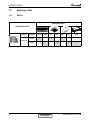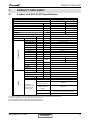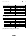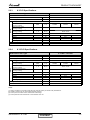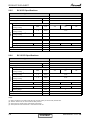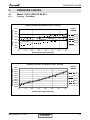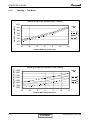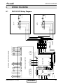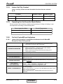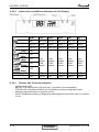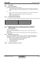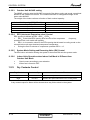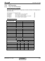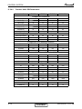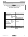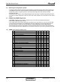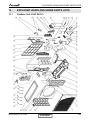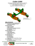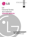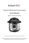
1
Multi Split DUO 50 DCI
Indoor Units
FLO 9 DCI
FLO 12 DCI
K 9 DCI
K 12 DCI
SX 9 DCI
SX 12 DCI
BS 12 DCI
Outdoor Units
DUO 50 DCI
REFRIGERANT
R410A
SM DUODCI 1-A.1 GB
HEAT PUMP
SEPTEMBER –– 2008
CONTENT
LIST OF EFFECTIVE PAGES
LIST OF EFFECTIVE PAGES
Note: Changes in the pages are indicated by a “Revision#” in the footer of each effected page
(when none indicates no changes in the relevant page). All pages in the following list represent
effected/ non effected pages divided by chapters.
Dates of issue for original and changed pages are:
Original ....... 0 ........ January 2005
Total number of pages in this publication is 56 consisting of the following:
Page
No.
Revision
No. #
Page
No.
Revision
No. #
Page
No.
Revision
No. #
Title ....................... 1
A ........................... 1
i ............................. 1
1-1 - 1-2 ................ 1
2-1 - 2-6 ................ 1
3-1 - 3-2 ................ 1
4-1 - 4-3 ................ 1
5-1 - 5-15 .............. 1
6-1 - 6-2 ................ 1
7-1 - 7-2 ................ 1
8-1 ........................ 1
9-1 - 9-2 ................ 1
10-1-10-2 .............. 1
11-1-11-16............. 1
12-1-12-6 .............. 1
13-1-13-2 .............. 1
Appendix -A ...........1
•
Zero in this column indicates an original page.
*Due to constant improvements please note that the data on this service manual can be modified
with out notice.
**Photos are not contractual
A
CONTENT
SM DUODCI 1-A.1 GB
TABLE OF CONTENTS
Table of Contents
1.
INTRODUCTION ...................................................................................................1-1
2.
PRODUCT DATA SHEET ......................................................................................2-1
3.
RATING CONDITIONS ..........................................................................................3-1
4.
OUTLINE DIMENSIONS .......................................................................................4-1
5.
PERFORMANCE DATA .......................................................................................5-1
6.
PRESSURE CURVES ...........................................................................................6-1
7.
ELECTRICAL DATA ..............................................................................................7-1
8.
WIRING DIAGRAMS .............................................................................................8-1
9.
REFRIGERATION DIAGRAMS .............................................................................9-1
10. TUBING CONNECTIONS......................................................................................10-1
11.
CONTROL SYSTEM .............................................................................................11-1
12. TROUBLESHOOTING ..........................................................................................12-1
13. EXPLODED VIEWS AND SPARE PARTS LISTS .................................................13-1
14. APPENDIX A .........................................................................................................14-1
SM DUODCI 1-A.1 GB
i
INTRODUCTION
1.
1.1
INTRODUCTION
General
The new DUO50 DCI is a high efficiency inverter technology outddor unit,
since it’s a lego concept unit, it can be matched to several types of inverter indoors, such
as:
wall mounted, cassette , floor/ceiling units, with a capacity range of 2.5 – 3.5 Kw for each
single indoor unit.
1.2
Main Features
•
•
•
•
•
•
o
o
•
•
•
•
•
•
•
•
1.3
DC Inverter
R410A
High COP (A class energy rating)
Lego Concept
Pre-Charged
Dry contact inputs:
STBY – when shorted, will force all indoors to STBY.
Night – when shorted, will force outdoor fan to low speed (in cool mode only)
Dry contact output – Alarm. Will be closed system is faulty.
Base heater connection.
Cooling operation at outdoor temperature down to -100C.
Heating operation at outdoor temperature down to -150C.
10 LED’s, shows both indoor and outdoor diagnostics.
Variable Speed DC Inverter outdoor fan.
M2L diagnostics softwear cable Port ( for PC).
Low noise level
Tubing Connections
Flare type interconnecting tubing to be produced on site.
For further detaiBS please refer to APPENDIX A on this manual, and to the relevant
indoor service Manual,
1.4
Inbox Documentation
Each indoor unit is supplied with its own installation and operation manuaBS.
SM DUODCI 1-A.1 GB
CONTENT
1-1
INTRODUCTION
1.5
Matching Table
1.5.1
R410A
INDOOR UNITS
OUTDOOR UNITS
MODEL
REFRIGER.
FLO25
R410A
√
FLO35
K25
K35
√
SX25
SX35
BS35
√
√
√
DUO50 DCI
R410A
1-2
√
CONTENT
√
SM DUODCI 1-A.1 GB
PRODUCT DATA SHEET
2.
PRODUCT DATA SHEET
2.1
Outdoor Unit DUO 50 DCI Specifications.
Model
DUO-50 DCI R410A
Function
Capacity(1)
Cooling
Heating
Kcal/hr
4300(1030~5570)
5330(820~6670)
Btu/hr
17050(4090~22100)
21140(3240~26430)
W
5000(1200~6480)
6200(950~7750)
(1)
W
1470(420~2160)
1670(375~2050)
W/W
3.4
3.71
Running Current
A
6.7
Starting Current
A
Total Input
E.E.R (Cooling) / C.O.P (Heating)(1)
7.7
10.5
Inrush Current
A
35
Power Supply
V/Ph/Hz
230V/ 1PH / 50Hz
Refrigerant control
Electronic expansion valve
Compressor type
Scroll DC Inverter
Model
Panasonic 5CS130XCC03
Starter type
---
Protection device
Outdoor SW control
OUTDOOR UNIT
Heat exchanger
Hydrophilic flat fin ,Grooved tube coil
Fan (drive) x No.
Propeller x 1
Airflow
m3/hr
2160
W
40
Motor output
Defrost method
Noise level
Reverse cycle
Pressure(4)
Power
Dimensions
Weight
PacKing
dimensions
Unit stacKing
W*D*H
W*D*H
dB(A)
52
53
62
63
mm
795*290*610
Kg
43
mm
945 * 395 * 655
units
3
Refrigerant
R410A
Charge(7.5m connection tube)
Kg
1500
liquid
mm
6.35
suction
mm
Fresh Air
Tube size
TUBING
O.D.
Connection
method between
the indoor and
outdoor units
NO
Flared
height difference
between indoor units
Max.5m
height difference
between indoor &
outdoor
Max.10m
tubing length
Standard 7.5m
Max.25m for one unit and 30m for total
additional charge
(1)
(2)
(3)
(4)
9.53
indoor & outdoor
No need
Rating conditions in accordance with ISO 5151 and ISO 13253 (for ducted units) and EN14511.
Airflow in ducted units; at nominal external static pressure.
Sound power in ducted units is measured at air discharge.
Sound pressure level measured at 1 meter distance from unit.
SM DUODCI 1-A.1 GB
CONTENT
2-1
PRODUCT DATA SHEET
2.2
Indoor Units Data
2.2.1
FLO 9 DCI Specifications
Model Indoor Unit / Type
FLO 9 DCI / Wall Mounted
Installation Method
FLARE
Fan Motor Output
Power Supply
W
V/Ph/Hz
20
220-240 / 1/ 50
INDOOR
Fan Type & Quantity
Crossflow *1
Airflow(2)
Cooling / Heating
H/M/L
m3/hr
Sound Power Level(3)
Cooling / Heating
L-H
dB (A)
39-50 / 39-51
Sound Pressure Level (4)
Cooling / Heating
L-H
dB (A)
26-38 / 26-39
W/H/D
mm
Kg
mm
Units
Condensate Drain Tube I.D.
Dimensions
Weight
PacKage Dimensions
StacKing Height
430/460
mm
W/H/D
Heating Elements
Moisture Removal
2.2.2
530/570
16
810
285
11
360
7
885
KW
L/hr
285
N/A
1
FLO 12 DCI / Wall Mounted
Installation Method
FLARE
Fan Motor Output
Power Supply
W
20
V/Ph/Hz
220-240 / 1/ 50
Fan Type & Quantity
INDOOR
202
FLO 12 DCI Specifications
Model Indoor Unit / Type
Airflow(2)
Cooling / Heating
Sound Power Level(3)
Cooling / Heating
Sound Pressure Level (4)
Cooling / Heating
Condensate Drain Tube I.D.
Dimensions
Weight
PacKage Dimensions
StacKing Height
Heating Elements
Moisture Removal
(1)
(2)
(3)
(4)
330/350
Crossflow *1
H/M/L
m3/hr
L-H
dB (A)
39-52 / 39-52
L-H
dB (A)
26-39 / 26-40
W/H/D
W/H/D
mm
mm
Kg
mm
Units
KW
L/hr
550/580
810
885
450/480
16
285
11
360
7
N/A
1.5
350/370
202
285
Rating conditions in accordance with ISO 5151 and ISO 13253 (for ducted units) and EN14511.
Airflow in ducted units; at nominal external static pressure.
Sound power in ducted units is measured at air discharge.
Sound pressure level measured at 1 meter distance from unit.
2-2
CONTENT
SM DUODCI 1-A.1 GB
PRODUCT DATA SHEET
2.2.3
K 9 DCI Specifications
Model Indoor Unit / Type
K 9 DCI / Cassette
Installation Method
FLARE
Fan Motor Output
Power Supply
W
36
V/Ph/Hz
220-240 / 1/ 50
Fan Type & Quantity
INDOOR
Airflow(2)
Cooling / Heating
Centifugal *1
H/M/L
m3/hr
L-H
dB (A)
42-48 / 42-47
L-H
dB (A)
32-38 / 32-37
Condensate Drain Tube I.D.
Dimensions
Weight
W/H/D
mm
mm
Kg
571
16
287
22.7
571
PacKage Dimensions
W/H/D
mm
685
415
685
Sound Power Level(3)
Cooling / Heating
Sound Pressure Level (4)
Cooling / Heating
StacKing Height
Heating Elements
Moisture Removal
2.2.4
530/600
500/530
Units
KW
L/hr
5
N/A
1
K 12 DCI Specifications
Model Indoor Unit / Type
K 12 DCI / Cassette
Installation Method
FLARE
Fan Motor Output
Power Supply
INDOOR
435/450
Fan Type & Quantity
Airflow(2)
Cooling / Heating
Sound Power Level(3)
Cooling / Heating
Sound Pressure Level (4)
Cooling / Heating
StacKing Height
220-240 / 1/ 50
3
H/M/L
m /hr
L-H
dB (A)
42-49 / 42-48
L-H
dB (A)
32-38 / 32-38
W/H/D
mm
580/620
mm
Weight
PacKage Dimensions
36
V/Ph/Hz
Centifugal *1
Condensate Drain Tube I.D.
Dimensions
W
mm
435/450
16
571
Kg
W/H/D
510/560
287
571
24.4
685
415
Units
5
Heating Elements
KW
N/A
Moisture Removal
L/hr
1.5
685
NOTE:
(1)
(2)
(3)
(4)
Rating conditions in accordance with ISO 5151 and ISO 13253 (for ducted units) and EN14511.
Airflow in ducted units; at nominal external static pressure.
Sound power in ducted units is measured at air discharge.
Sound pressure level measured at 1 meter distance from unit.
SM DUODCI 1-A.1 GB
CONTENT
2-3
PRODUCT DATA SHEET
2.2.5
SX 9 DCI Specifications
Model Indoor Unit / Type
SX 9 DCI
Installation Method
FLARE
Fan Motor Output
Power Supply
W
36
V/Ph/Hz
220-240 / 1/ 50
Fan Type & Quantity
Centifugal *2
INDOOR
(2)
Airflow
Cooling / Heating
H/M/L
m3/hr
Sound Power Level(3)
Cooling / Heating
L-H
dB (A)
47-50
Sound Pressure Level (4)
Cooling / Heating
L-H
dB (A)
35-39
mm
16
Condensate Drain Tube I.D.
Dimensions
W/H/D
Weight
mm
400
350
820
630
Kg
PacKage Dimensions
W/H/D
StacKing Height
mm
890
710
7
Heating Elements
KW
N/A
Moisture Removal
L/hr
1
280
SX 12 DCI Specifications
Model Indoor Unit / Type
SX 12 DCI
Installation Method
FLARE
Fan Motor Output
Power Supply
W
36
V/Ph/Hz
220-240 / 1/ 50
Fan Type & Quantity
INDOOR
190
21
Units
2.2.6
300
Centifugal *2
Airflow(2)
Cooling / Heating
H/M/L
m3/hr
Sound Power Level(3)
Cooling / Heating
L-H
dB (A)
51-56
Sound Pressure Level (4)
Cooling / Heating
L-H
dB (A)
45-38
W/H/D
mm
Condensate Drain Tube I.D.
Dimensions
mm
Weight
PacKage Dimensions
StacKing Height
450
mm
300
16
820
Kg
W/H/D
400
630
190
22
890
710
Units
7
Heating Elements
KW
N/A
Moisture Removal
L/hr
1.9
280
NOTE:
(1)
(2)
(3)
(4)
Rating conditions in accordance with ISO 5151 and ISO 13253 (for ducted units) and EN14511.
Airflow in ducted units; at nominal external static pressure.
Sound power in ducted units is measured at air discharge.
Sound pressure level measured at 1 meter distance from unit.
2-4
CONTENT
SM DUODCI 1-A.1 GB
PRODUCT DATA SHEET
2.2.7
BS 12 DCI Specifications
Model Indoor Unit / Type
BS 12 DCI
Installation Method
FLARE
Fan Motor Output
Power Supply
W
36
V/Ph/Hz
220-240 / 1/ 50
INDOOR
Fan Type & Quantity
Centifugal *2
Airflow(2)
Cooling / Heating
H/M/L
m3/hr
Sound Power Level(3)
Cooling / Heating
L-H
dB (A)
52-59
Sound Pressure Level (4)
Cooling / Heating
L-H
dB (A)
35-42
W/H/D
mm
Condensate Drain Tube I.D.
Dimensions
mm
Weight
PacKage Dimensions
StacKing Height
830
mm
530
16
860
Kg
W/H/D
700
245
680
30.0
1055
305
Units
6
Heating Elements
KW
N/A
Moisture Removal
L/hr
1.3
728
NOTE:
(1)
(2)
(3)
(4)
Rating conditions in accordance with ISO 5151 and ISO 13253 (for ducted units) and EN14511.
Airflow in ducted units; at nominal external static pressure.
Sound power in ducted units is measured at air discharge.
Sound pressure level measured at 1 meter distance from unit.
SM DUODCI 1-A.1 GB
CONTENT
2-5
PRODUCT DATA SHEET
2.3
Data For Outdoor Unit DUO 50 DCI Combinations
(Based on FLO)
Cooling
Heating
Room A
Room B
Total
Capacity
[W]
[W]
[W]
[W]
[W]
[W]
[W]
[W]
25
2500
-
2500
(1220 - 3700)
680
(420 - 980)
3400
-
3400
(950 - 4000)
1135
(375 - 1250)
35
3500
-
3500
(1220 - 4350)
1030
(420 - 1275)
4200
-
4200
(950 - 5200)
1575
(375 - 1760)
25+25
2500
2500
5000
(1400 - 6000)
1470
(410 - 2100)
3100
3100
6200
(1250 - 7100)
1670
(320 - 1960)
25+35
2500
3000
5500
(1400 - 6240)
1850
(410 - 2130)
3100
3450
6550
(1250 - 7400)
1760
(320 - 2020)
35+35
3000
3000
6000
(1400 - 6480)
2040
(410 - 2160)
3450
3450
6900
(1250 - 7750)
1970
(320 - 2050)
Indoor Units
Combinations
2.3.1
Power Input
Room A
Room B
Total
Capacity
Power Input
Correction Factors:
Capacity
Power input
Model
SX25 DCI
Cooling
Heating
Cooling
Heating
1.0
0.95
1.0
1.08
SX35 DCI
1.02
0.96
1.0
1.08
BS35 DCI
1.02
0.95
1.0
0.91
K25 DCI
K35 DCI
1.02
1.01
1.01
1.01
1.06
0.97
1.05
0.99
2.3.2
Calculation Example.
FLO25+K35 Cooling Mode:
Indoor Unit
Room A – FLO25
Cooling Capacity [W]
Power Input [W]
2500
1850 x (2500/5000) = 840
Room B – K35
(3000 x 1.06) = 3180
1850 x (3000/5000) x 1.05 = 1059
Total
(2500+3180) = 5680
840+1059 = 1899
2.3.3
K35+K35 Heating Mode:
Heating Capacity [W]
Power Input [W]
Room A – K35
Indoor Unit
(3000 x 0.97) = 2910
(2040 x 0.99) = 2019
Room B – K35
(3000 x 0.97) = 2910
(2040 x 0.99) = 2019
Total
(2910+2910) = 5820
(2019+2019) = 4038
2-6
CONTENT
SM DUODCI 1-A.1 GB
RATING CONDITIONS
3.
RATING CONDITIONS
Standard conditions in accordance with ISO 5151, ISO 13253 (for ducted units)
and EN 14511.
Cooling:
Indoor:
27oC DB 19oC WB
Outdoor: 35 oC DB
Heating:
Indoor:
20oC DB
Outdoor: 7oC DB 6oC WB
3.1
Operating Limits
Indoor
Cooling
Heating
Voltage
SM DUODCI 1-A.1 GB
Outdoor
Upper limit
32oC DB 23oC WB
46oC DB
Lower limit
21oC DB 15oC WB
-10oC DB
Upper limit
27oC DB
24oC DB 18oC WB
Lower limit
10oC DB
-15oC DB -16oC WB
1PH
198 – 264 V
3PH
N/A
CONTENT
3-1
OUTLINE DIMENSIONS
4.
OUTLINE DIMENSIONS
4.1
Indoor Unit: FLO 9 / 12 DCI
4.2
Indoor Unit: K 9 / 12 DCI
SM DUODCI 1-A.1 GB
CONTENT
4-1
OUTLINE DIMENSIONS
4.3
Indoor Unit: SX 9 / 12 DCI
4.4
Indoor Unit: BS 12 DCI
4-2
CONTENT
SM DUODCI 1-A.1 GB
OUTLINE DIMENSIONS
4.3
Outdoor Unit: DUO 50 DCI
SM DUODCI 1-A.1 GB
CONTENT
4-3
PERFORMANCE DATA
5.
PERFORMANCE DATA
5.1
FLO 9 DCI
5.1.1
Cooling Capacity (KW) - Run Mode (Unit A or B)
230[V] : Indoor Fan at High Speed.
ID COIL ENTERING AIR DB/WB TEMPERATURE [0C]
OD COIL
ENTERING AIR DB
TEMPERATURE [0C]
DATA
TC
SC
PI
TC
SC
PI
TC
SC
PI
TC
SC
PI
TC
SC
PI
TC
SC
PI
-10 - 20
(protection range)
25
30
35
40
46
22/15
24/17
27/19
29/21
32/23
2.42
1.72
0.58
2.30
1.67
0.65
2.18
1.63
0.71
2.07
1.59
0.78
1.93
1.53
0.86
80 - 110 % of nominal
80 - 105 % of nominal
25 - 50 % of nominal
2.57
2.73
2.89
1.75
1.79
1.82
0.59
0.60
0.61
2.46
2.62
2.77
1.71
1.74
1.78
0.67
0.66
0.68
2.34
2.66
2.50
1.66
1.70
1.74
0.74
0.72
0.75
2.23
2.54
2.38
1.62
1.66
1.69
0.79
0.80
0.81
2.09
2.24
2.40
1.57
1.60
1.64
0.87
0.88
0.89
3.05
1.86
0.62
2.93
1.81
0.69
2.82
1.77
0.76
2.70
1.73
0.82
2.56
1.67
0.91
LEGEND
TC
SC
PI
WB
DB
ID
OD
5.1.2
–
–
–
–
–
–
–
Total Cooling Capacity, KW
Sensible Capacity, KW
Power Input, KW
Wet Bulb Temp., (oC)
Dry Bulb Temp., (oC)
Indoor
Outdoor
Capacity Correction Factors
1.2
Capacity Ration
1.1
1
0.9
0.8
0.7
0.6
0.5
20
25
30
35
40
45
Outdoor Temperature [deg C]
SM DUODCI 1-A.1 GB
CONTENT
5-1
PERFORMANCE DATA
5.1.3
Heating Capacity (KW) - Run Mode(Unit A or B)
230[V] : Indoor Fan at High Speed.
ID COIL ENTERING AIR DB TEMPERATURE [0C]
OD COIL ENTERING
AIR DB/WB
TEMPERATURE [0C]
-15/-16
-10/-12
-7/-8
-1/-2
2/1
7/6
10/9
15/12
15-24
(Protection Range)
DATA
15
20
25
TC
PI
TC
PI
TC
PI
TC
PI
TC
PI
TC
PI
TC
PI
TC
PI
TC
PI
1.97
0.50
2.20
0.60
2.36
0.68
2.45
0.72
2.50
0.75
3.24
0.78
3.42
0.83
3.60
0.88
1.84
0.55
2.06
0.65
2.23
0.73
2.31
0.77
2.37
0.80
3.10
0.84
3.28
0.88
3.46
0.93
85 - 105 % of nominal
80 - 120 % of nominal
1.70
0.60
1.92
0.71
2.09
0.78
2.17
0.82
2.23
0.85
2.96
0.89
3.14
0.93
3.32
0.98
LEGEND
TC
PI
WB
DB
ID
OU
5.1.4
–
–
–
–
–
–
Total Heating Capacity, KW
Power Input, KW
Wet Bulb Temp., (oC)
Dry Bulb Temp., (oC)
Indoor
Outdoor
Capacity Correction Factors
1.2
Capacity Ration
1.1
1
0.9
0.8
0.7
0.6
0.5
-15
-10
-5
0
5
10
15
Outdoor WB Temperature [deg C]
5-2
CONTENT
SM DUODCI 1-A.1 GB
PERFORMANCE DATA
5.2
FLO 12 DCI
5.2.1
Cooling Capacity (KW) - Run Mode (Unit A or B)
230[V] : Indoor Fan at High Speed.
ID COIL ENTERING AIR DB/WB TEMPERATURE [0C]
OD COIL
ENTERING AIR DB
TEMPERATURE [0C]
DATA
TC
SC
PI
TC
SC
PI
TC
SC
PI
TC
SC
PI
TC
SC
PI
TC
SC
PI
-10 - 20
(protection range)
25
30
35
40
(Protection Range)
46
(Protection Range)
22/15
24/17
27/19
29/21
32/23
2.90
2.06
0.80
2.76
2.01
0.90
2.62
1.96
0.99
2.48
1.90
1.08
2.31
1.84
1.20
80 - 110 % of nominal
80 - 105 % of nominal
25 - 50 % of nominal
3.09
3.28
3.47
2.10
2.14
2.19
0.82
0.83
0.85
2.95
3.14
3.33
2.05
2.09
2.13
0.93
0.91
0.94
2.81
3.19
3.00
2.00
2.04
2.08
1.02
1.00
1.04
2.67
3.05
2.86
1.95
1.99
2.03
1.10
1.11
1.13
2.50
2.69
2.88
1.88
1.93
1.97
1.21
1.23
1.24
3.66
2.23
0.86
3.52
2.18
0.96
3.38
2.12
1.05
3.24
2.07
1.14
3.07
2.01
1.26
LEGEND
TC
SC
PI
WB
DB
ID
OD
5.2.2
–
–
–
–
–
–
–
Total Cooling Capacity, KW
Sensible Capacity, KW
Power Input, KW
Wet Bulb Temp., (oC)
Dry Bulb Temp., (oC)
Indoor
Outdoor
Capacity Correction Factors
Cooling Capacity Ratio Vs. Outdoor Temperature
Capacity Ration
1.2
1.1
1
0.9
0.8
0.7
0.6
0.5
20
25
30
35
40
45
Outdoor Temperature [deg C]
SM DUODCI 1-A.1 GB
CONTENT
5-3
PERFORMANCE DATA
5.2.3
Heating Capacity (KW) - Run Mode(Unit A or B)
230[V] : Indoor Fan at High Speed.
ID COIL ENTERING AIR DB TEMPERATURE [0C]
OD COIL ENTERING
AIR DB/WB
TEMPERATURE [0C]
-15/-16
-10/-12
-7/-8
-1/-2
2/1
7/6
10/9
15/12
15-24
(Protection Range)
DATA
15
20
25
TC
PI
TC
PI
TC
PI
TC
PI
TC
PI
TC
PI
TC
PI
TC
PI
TC
PI
2.20
0.59
2.44
0.71
2.63
0.80
2.72
0.85
2.79
0.88
3.60
0.92
3.80
0.98
4.00
1.04
2.04
0.65
2.29
0.77
2.48
0.86
2.57
0.91
2.63
0.94
1.89
0.71
2.14
0.83
2.32
0.92
2.42
0.97
2.48
1.00
3.30
1.05
3.50
1.10
3.69
1.16
3.45
0.99
3.65
1.04
3.85
1.10
85 - 105 % of nominal
80 - 120 % of nominal
LEGEND
TC
PI
WB
DB
ID
OU
5.3.4
–
–
–
–
–
–
Total Heating Capacity, KW
Power Input, KW
Wet Bulb Temp., (oC)
Dry Bulb Temp., (oC)
Indoor
Outdoor
Capacity Correction Factors
Heating Capacity Ratio Vs. Outdoor Temperature
Capacity Ration
1.2
1.1
1
0.9
0.8
0.7
0.6
0.5
-15
-10
-5
0
5
10
15
Outdoor WB Temperature [deg C]
5-4
CONTENT
SM DUODCI 1-A.1 GB
PERFORMANCE DATA
5.3
K 9 DCI
5.3.1
Cooling Capacity (KW) - Run Mode(Unit A or B)
230[V] : Indoor Fan at High Speed.
ID COIL ENTERING AIR DB/WB TEMPERATURE [0C]
OD COIL
ENTERING AIR DB
TEMPERATURE [0C]
DATA
TC
SC
PI
TC
SC
PI
TC
SC
PI
TC
SC
PI
TC
SC
PI
TC
SC
PI
-10 - 20
(protection range)
25
30
35
40
46
22/15
24/17
27/19
29/21
32/23
2.46
1.75
0.58
2.35
1.71
0.65
2.23
1.66
0.72
2.11
1.62
0.79
1.97
1.57
0.87
80 - 110 % of nominal
80 - 105 % of nominal
25 - 50 % of nominal
2.63
2.79
2.95
1.79
1.82
1.86
0.59
0.61
0.62
2.51
2.67
2.83
1.74
1.78
1.81
0.67
0.66
0.68
2.39
2.71
2.55
1.70
1.73
1.77
0.74
0.73
0.75
2.27
2.59
2.43
1.65
1.69
1.73
0.80
0.81
0.82
2.13
2.29
2.45
1.60
1.64
1.67
0.88
0.89
0.90
3.11
1.89
0.63
2.99
1.85
0.70
2.87
1.81
0.76
2.75
1.76
0.83
2.61
1.71
0.91
LEGEND
TC
SC
PI
WB
DB
ID
OD
5.3.2
–
–
–
–
–
–
–
Total Cooling Capacity, KW
Sensible Capacity, KW
Power Input, KW
Wet Bulb Temp., (oC)
Dry Bulb Temp., (oC)
Indoor
Outdoor
Capacity Correction Factors
Cooling Capacity Ratio Vs. Outdoor Temperature
Capacity Ration
1.2
1.1
1
0.9
0.8
0.7
0.6
0.5
20
25
30
35
40
45
Outdoor Temperature [deg C]
SM DUODCI 1-A.1 GB
CONTENT
5-5
PERFORMANCE DATA
5.3.3
Heating Capacity (KW) - Run Mode(Unit A or B)
230[V] : Indoor Fan at High Speed.
ID COIL ENTERING AIR DB TEMPERATURE [0C]
OD COIL ENTERING
AIR DB/WB
TEMPERATURE [0C]
-15/-16
-10/-12
-7/-8
-1/-2
2/1
7/6
10/9
15/12
15-24
(Protection Range)
DATA
15
20
25
TC
PI
TC
PI
TC
PI
TC
PI
TC
PI
TC
PI
TC
PI
TC
PI
TC
PI
1.99
0.52
2.22
0.62
2.39
0.70
2.47
0.74
2.53
0.77
3.27
0.81
3.45
0.86
3.63
0.90
1.85
0.57
2.08
0.67
2.25
0.75
2.33
0.79
2.39
0.82
1.71
0.62
1.94
0.73
2.11
0.81
2.19
0.85
2.25
0.87
2.99
0.91
3.17
0.96
3.35
1.01
3.13
0.86
3.31
0.91
3.49
0.96
85 - 105 % of nominal
80 - 120 % of nominal
LEGEND
TC
PI
WB
DB
ID
OU
5.3.4
–
–
–
–
–
–
Total Heating Capacity, KW
Power Input, KW
Wet Bulb Temp., (oC)
Dry Bulb Temp., (oC)
Indoor
Outdoor
Capacity Correction Factors
Cooling Capacity Ratio Vs. Outdoor Temperature
Capacity Ration
1.2
1.1
1
0.9
0.8
0.7
0.6
0.5
20
25
30
35
40
45
Outdoor Temperature [deg C]
5-6
CONTENT
SM DUODCI 1-A.1 GB
PERFORMANCE DATA
5.4
K 12 DCI
5.4.1.
Cooling Capacity (KW) - Run Mode (Unit A or B)
230[V] : Indoor Fan at High Speed.
ID COIL ENTERING AIR DB/WB TEMPERATURE [0C]
OD COIL
ENTERING AIR DB
TEMPERATURE [0C]
DATA
TC
SC
PI
TC
SC
PI
TC
SC
PI
TC
SC
PI
TC
SC
PI
TC
SC
PI
-10 - 20
(protection range)
25
30
35
40
46
22/15
24/17
27/19
29/21
32/23
3.07
2.18
0.84
2.93
2.13
0.94
2.78
2.07
1.04
2.63
2.02
1.14
2.45
1.95
1.25
80 - 110 % of nominal
80 - 105 % of nominal
25 - 50 % of nominal
3.27
3.48
3.68
2.23
2.27
2.31
0.86
0.87
0.89
3.13
3.33
3.53
2.17
2.22
2.26
0.97
0.96
0.99
2.98
3.38
3.18
2.12
2.16
2.20
1.07
1.05
1.09
2.83
3.23
3.03
2.06
2.10
2.15
1.15
1.17
1.18
2.65
2.85
3.06
1.99
2.04
2.08
1.27
1.29
1.30
3.88
2.36
0.91
3.73
2.30
1.00
3.58
2.25
1.10
3.43
2.19
1.20
3.26
2.13
1.32
LEGEND
TC
SC
PI
WB
DB
ID
OD
5.4.2
–
–
–
–
–
–
–
Total Cooling Capacity, KW
Sensible Capacity, KW
Power Input, KW
Wet Bulb Temp., (oC)
Dry Bulb Temp., (oC)
Indoor
Outdoor
Capacity Correction Factors
Cooling Capacity Ratio Vs. Outdoor Temperature
Capacity Ration
1.2
1.1
1
0.9
0.8
0.7
0.6
0.5
20
25
30
35
40
45
Outdoor Temperature [deg C]
SM DUODCI 1-A.1 GB
CONTENT
5-7
PERFORMANCE DATA
5.4.3
Heating Capacity (KW) - Run Mode (Unit A or B)
230[V] : Indoor Fan at High Speed.
ID COIL ENTERING AIR DB TEMPERATURE [0C]
OD COIL ENTERING
AIR DB/WB
TEMPERATURE [0C]
-15/-16
-10/-12
-7/-8
-1/-2
2/1
7/6
10/9
15/12
15-24
(Protection Range)
DATA
15
20
25
TC
PI
TC
PI
TC
PI
TC
PI
TC
PI
TC
PI
TC
PI
TC
PI
TC
PI
2.13
0.59
2.37
0.71
2.55
0.80
2.64
0.84
2.71
0.87
3.50
0.92
3.69
0.97
3.88
1.02
1.98
0.64
2.22
0.76
2.41
0.85
2.50
0.90
2.56
0.93
1.83
0.70
2.08
0.82
2.26
0.91
2.35
0.96
2.41
0.99
3.20
1.03
3.39
1.09
3.59
1.14
3.35
0.98
3.54
1.03
3.74
1.08
85 - 105 % of nominal
80 - 120 % of nominal
LEGEND
TC
PI
WB
DB
ID
OU
5.4.4
–
–
–
–
–
–
Total Heating Capacity, KW
Power Input, KW
Wet Bulb Temp., (oC)
Dry Bulb Temp., (oC)
Indoor
Outdoor
Capacity Correction Factors
Heating Capacity Ratio Vs. Outdoor Temperature
Capacity Ration
1.2
1.1
1
0.9
0.8
0.7
0.6
0.5
-15
-10
-5
0
5
10
15
Outdoor WB Temperature [deg C]
5-8
CONTENT
SM DUODCI 1-A.1 GB
PERFORMANCE DATA
5.5
SX 9 DCI
5.5.1.
Cooling Capacity (KW) - Run Mode (Unit A or B)
230[V] : Indoor Fan at High Speed.
ID COIL ENTERING AIR DB/WB TEMPERATURE [ºC]
OD COIL
ENTERING AIR DB
TEMPERATURE [ºC]
DATA
TC
SC
PI
TC
SC
PI
TC
SC
PI
TC
SC
PI
TC
SC
PI
TC
SC
PI
-10 - 20
(protection range)
25
30
35
40
46
22/15
24/17
27/19
29/21
32/23
2.42
1.72
0.58
2.30
1.67
0.65
2.18
1.63
0.71
2.07
1.59
0.78
1.93
1.53
0.86
80 - 110 % of nominal
80 - 105 % of nominal
25 - 50 % of nominal
2.57
2.73
2.89
1.75
1.79
1.82
0.59
0.60
0.61
2.46
2.62
2.77
1.71
1.74
1.78
0.67
0.66
0.68
2.34
2.66
2.50
1.66
1.70
1.74
0.74
0.72
0.75
2.23
2.54
2.38
1.62
1.66
1.69
0.79
0.80
0.81
2.09
2.24
2.40
1.57
1.60
1.64
0.87
0.88
0.89
3.05
1.86
0.62
2.93
1.81
0.69
2.82
1.77
0.76
2.70
1.73
0.82
2.56
1.67
0.91
LEGEND
TC
SC
PI
WB
DB
ID
OD
5.5.2
–
–
–
–
–
–
–
Total Cooling Capacity, KW
Sensible Capacity, KW
Power Input, KW
Wet Bulb Temp., (oC)
Dry Bulb Temp., (oC)
Indoor
Outdoor
Capacity Correction Factors
Cooling Capacity Ratio Vs. Outdoor Temperature
Capacity Ration
1.2
1.1
1
0.9
0.8
0.7
0.6
0.5
20
25
30
35
40
45
Outdoor Temperature [deg C]
SM DUODCI 1-A.1 GB
CONTENT
5-9
PERFORMANCE DATA
5.5.3
Heating Capacity (KW) - Run Mode (Unit A or B)
230[V] : Indoor Fan at High Speed.
ID COIL ENTERING AIR DB TEMPERATURE [ºC]
OD COIL ENTERING
AIR DB/WB
TEMPERATURE [ºC]
-15/-16
-10/-12
-7/-8
-1/-2
2/1
7/6
10/9
15/12
15-24
(Protection Range)
DATA
15
20
25
TC
PI
TC
PI
TC
PI
TC
PI
TC
PI
TC
PI
TC
PI
TC
PI
TC
PI
1.87
0.54
2.08
0.65
2.24
0.73
2.32
0.78
2.37
0.80
3.07
0.85
3.24
0.90
3.41
0.95
1.74
0.60
1.95
0.71
2.11
0.79
2.19
0.83
2.24
0.86
2.94
0.90
3.11
0.95
3.28
1.00
85 - 105 % of nominal
80 - 120 % of nominal
1.61
0.65
1.82
0.76
1.98
0.84
2.06
0.89
2.11
0.91
2.81
0.95
2.98
1.01
3.15
1.06
LEGEND
TC
PI
WB
DB
ID
OU
5.5.4
–
–
–
–
–
–
Total Heating Capacity, KW
Power Input, KW
Wet Bulb Temp., (oC)
Dry Bulb Temp., (oC)
Indoor
Outdoor
Capacity Correction Factors
Heating Capacity Ratio Vs. Outdoor Temperature
Capacity Ration
1.2
1.1
1
0.9
0.8
0.7
0.6
0.5
-15
-10
-5
0
5
10
15
Outdoor WB Temperature [deg C]
5-10
CONTENT
SM DUODCI 1-A.1 GB
PERFORMANCE DATA
5.6
SX 12 DCI
5.6.1.
Cooling Capacity (KW) - Run Mode (Unit A or B)
230[V] : Indoor Fan at High Speed.
ID COIL ENTERING AIR DB/WB TEMPERATURE [ºC]
OD COIL
ENTERING AIR DB
TEMPERATURE [ºC]
DATA
TC
SC
PI
TC
SC
PI
TC
SC
PI
TC
SC
PI
TC
SC
PI
TC
SC
PI
-10 - 20
(protection range)
25
30
35
40
46
22/15
24/17
27/19
29/21
32/23
2.96
2.06
0.80
2.82
2.01
0.90
2.67
1.96
0.99
2.53
1.90
1.08
2.36
1.84
1.20
80 - 110 % of nominal
80 - 105 % of nominal
25 - 50 % of nominal
3.15
3.34
3.54
2.10
2.14
2.19
0.82
0.83
0.85
3.01
3.20
3.40
2.05
2.09
2.13
0.93
0.91
0.94
2.87
3.25
3.06
2.00
2.04
2.08
1.02
1.00
1.04
2.72
3.11
2.92
1.95
1.99
2.03
1.10
1.11
1.13
2.55
2.75
2.94
1.88
1.93
1.97
1.21
1.23
1.24
3.73
2.23
0.86
3.59
2.18
0.96
3.45
2.12
1.05
3.30
2.07
1.14
3.13
2.01
1.26
LEGEND
TC
SC
PI
WB
DB
ID
OD
5.6.2
–
–
–
–
–
–
–
Total Cooling Capacity, KW
Sensible Capacity, KW
Power Input, KW
Wet Bulb Temp., (oC)
Dry Bulb Temp., (oC)
Indoor
Outdoor
Capacity Correction Factors
Cooling Capacity Ratio Vs. Outdoor Temperature
Capacity Ration
1.2
1.1
1
0.9
0.8
0.7
0.6
0.5
20
25
30
35
40
45
Outdoor Temperature [deg C]
SM DUODCI 1-A.1 GB
CONTENT
5-11
PERFORMANCE DATA
5.6.3
Heating Capacity (KW) - Run Mode (Unit A or B)
230[V] : Indoor Fan at High Speed.
ID COIL ENTERING AIR DB TEMPERATURE [ºC]
OD COIL ENTERING
AIR DB/WB
TEMPERATURE [ºC]
-15/-16
-10/-12
-7/-8
-1/-2
2/1
7/6
10/9
15/12
15-24
(Protection Range)
DATA
15
20
25
TC
PI
TC
PI
TC
PI
TC
PI
TC
PI
TC
PI
TC
PI
TC
PI
TC
PI
2.11
0.64
2.35
0.77
2.52
0.87
2.61
0.92
2.67
0.95
3.46
1.00
3.65
1.06
3.84
1.12
1.96
0.70
2.20
0.83
2.38
0.93
2.47
0.98
2.53
1.01
3.31
1.06
3.50
1.12
3.69
1.18
85 - 105 % of nominal
80 - 120 % of nominal
1.81
0.77
2.05
0.90
2.23
1.00
2.32
1.05
2.38
1.08
3.16
1.13
3.35
1.19
3.54
1.25
LEGEND
TC
PI
WB
DB
ID
OU
5.6.4
–
–
–
–
–
–
Total Heating Capacity, KW
Power Input, KW
Wet Bulb Temp., (oC)
Dry Bulb Temp., (oC)
Indoor
Outdoor
Capacity Correction Factors
Heating Capacity Ratio Vs. Outdoor Temperature
Capacity Ration
1.2
1.1
1
0.9
0.8
0.7
0.6
0.5
-15
-10
-5
0
5
10
15
Outdoor WB Temperature [deg C]
5-12
CONTENT
SM DUODCI 1-A.1 GB
PERFORMANCE DATA
5.7
BS 12 DCI
5.7.1.
Cooling Capacity (KW) - Run Mode (Unit A or B)
230[V] : Indoor Fan at High Speed.
ID COIL ENTERING AIR DB/WB TEMPERATURE [ºC]
OD COIL
ENTERING AIR DB
TEMPERATURE [ºC]
DATA
TC
SC
PI
TC
SC
PI
TC
SC
PI
TC
SC
PI
TC
SC
PI
TC
SC
PI
-10 - 20
(protection range)
25
30
35
40
46
22/15
24/17
27/19
29/21
32/23
2.96
2.06
0.80
2.82
2.01
0.90
2.67
1.96
0.99
2.53
1.90
1.08
2.36
1.84
1.20
80 - 110 % of nominal
80 - 105 % of nominal
25 - 50 % of nominal
3.15
3.34
3.54
2.10
2.14
2.19
0.82
0.83
0.85
3.01
3.20
3.40
2.05
2.09
2.13
0.93
0.91
0.94
2.87
3.25
3.06
2.00
2.04
2.08
1.02
1.00
1.04
2.72
3.11
2.92
1.95
1.99
2.03
1.10
1.11
1.13
2.55
2.75
2.94
1.88
1.93
1.97
1.21
1.23
1.24
3.73
2.23
0.86
3.59
2.18
0.96
3.45
2.12
1.05
3.30
2.07
1.14
3.13
2.01
1.26
LEGEND
TC
SC
PI
WB
DB
ID
OD
5.7.2
–
–
–
–
–
–
–
Total Cooling Capacity, KW
Sensible Capacity, KW
Power Input, KW
Wet Bulb Temp., (oC)
Dry Bulb Temp., (oC)
Indoor
Outdoor
Capacity Correction Factors
Cooling Capacity Ratio Vs. Outdoor Temperature
Capacity Ration
1.2
1.1
1
0.9
0.8
0.7
0.6
0.5
20
25
30
35
40
45
Outdoor Temperature [deg C]
SM DUODCI 1-A.1 GB
CONTENT
5-13
PERFORMANCE DATA
5.7.3
Heating Capacity (KW) - Run Mode (Unit A or B)
230[V] : Indoor Fan at High Speed.
ID COIL ENTERING AIR DB TEMPERATURE [ºC]
OD COIL ENTERING
AIR DB/WB
TEMPERATURE [ºC]
-15/-16
-10/-12
-7/-8
-1/-2
2/1
7/6
10/9
15/12
15-24
(Protection Range)
DATA
15
20
25
TC
PI
TC
PI
TC
PI
TC
PI
TC
PI
TC
PI
TC
PI
TC
PI
TC
PI
2.09
0.54
2.32
0.65
2.50
0.73
2.59
0.78
2.65
0.80
3.43
0.85
3.61
0.90
3.80
0.95
1.94
0.60
2.18
0.71
2.36
0.79
2.44
0.83
2.50
0.86
3.28
0.90
3.47
0.95
3.66
1.00
85 - 105 % of nominal
80 - 120 % of nominal
1.80
0.65
2.03
0.76
2.21
0.84
2.30
0.89
2.36
0.91
3.13
0.95
3.32
1.01
3.51
1.06
LEGEND
TC
PI
WB
DB
ID
OU
5.7.4
–
–
–
–
–
–
Total Heating Capacity, KW
Power Input, KW
Wet Bulb Temp., (oC)
Dry Bulb Temp., (oC)
Indoor
Outdoor
Capacity Correction Factors
Heating Capacity Ratio Vs. Outdoor Temperature
Capacity Ration
1.2
1.1
1
0.9
0.8
0.7
0.6
0.5
-15
-10
-5
0
5
10
15
Outdoor WB Temperature [deg C]
5-14
CONTENT
SM DUODCI 1-A.1 GB
PERFORMANCE DATA
5.8
Capacity Correction Factor Due to Tubing Length
(OneWay)
5.8.1
FLO25, FLO35, K25, K35
5.8.2
Cooling
Capacity Ratio VS.Tubing Length - Cooling
Capacity Ratio
1.02
1.00
0.98
0.96
0.94
0.92
0.90
0.88
4
5.8.3
6
8
10
12
14 16 18 20 22
Tubing Length [m]
24
26
28
30
26
28
30
Heating
Capacity Ratio VS. Tubing Length - Heating
Capacity Ratio
1.02
1.00
0.98
0.96
0.94
0.92
0.90
0.88
4
SM DUODCI 1-A.1 GB
6
8
10
12 14 16 18 20
Tubing Length [m]
CONTENT
22
24
5-15
PRESSURE CURVES
6.
PRESSURE CURVES
6.1
Model: FLO 9+25 DUO 50 DCI
6.1.1
Cooling – Test Mode
Suction Pressure Vs. Outdoor Temp’ - Cooling
Suction Pressure [kPa]
1400
Indoor
DB/WB
1300
1200
22/15
24/17
1100
1000
27/19
29/21
900
32/23
800
700
10
15
20
25
30
35
Outdoor DB Temperature[ºC]
40
45
Discharge Pressure [kPa]
Discharge Pressure Vs. Outdoor Temp’- Cooling
Indoor
DB/WB
4000
3750
3500
3250
3000
2750
2500
2250
2000
1750
1500
22/15
24/17
27/19
29/21
32/23
10
15
20
25
30
35
40
45
Outdoor DB Temperature[ºC]
SM DUODCI 1-A.1 GB
CONTENT
6-1
PRESSURE CURVES
6.1.2
Heading – Test Mode
Suction Pressure Vs. Outdoor Temp’ - Heating
Suction Pressure [kPa]
1000
Indoor
DB
900
800
15
700
20
600
25
500
400
300
-15
-10
-5
0
5
10
15
Outdoor WB Temperature[ºC]
Discharge Pressure [kPa]
Discharge Pressure Vs. Outdoor Temp’- Heating
3250
3000
2750
2500
2250
2000
1750
1500
Indoor
DB
15
20
25
-15
-10
-5
0
5
10
15
Outdoor WB Temperature[ºC]
6-2
CONTENT
SM DUODCI 1-A.1 GB
ELECTRICAL DATA
7.
ELECTRICAL DATA
Power Supply
Connected to
1 PH, 220-240 VAC, 50Hz
Outdoor
Maximum Current
13.7 A
Inrush Current
35 A
Starting Current
10 A
Circuit breaKer
16 A
3 X 2.5 mm2
Power supply wiring - No. x cross section
2 X 4 X 1.5 mm2
Interconnecting cable - No. x cross section
Note:
• Inrush current is the current when power is up. (charging the DC capacitors at outdoor unit
controller).
• Starting current is the current when starting the compressor
NOTE
Power wiring cord should comply with local lows and electrical
regulations requirements.
SM DUODCI 1-A.1 GB
CONTENT
7-1
SM DUODCI 1-A.1 GB
Choke
coil
CONTENT
J50
J51
5
RGT2
To metal sheet
1 2 3
P2
J41
1 2 3 4 5 6
Alarm
P11 P10 P70
Night
Stdby
1 23 4
MSMP
PCB
1 23 4
RGT1
J40
6
COM2
COM1
COM
N
L
EEV2
4527314
4
1 2 3 4 5 6
J91
3
P1
2
OFAN
1 2 3 4 5 6
P15
Vm=310V DC
EEV1
J90
2
1
Base
heater
GND
Vcc =15V DC
Vsp=0-6.5V DC
1 2 3 4 5 6
P7 EEV
N
L
N
COM
EMI filter PCB
N
COM N-COM
L-F N-F COM
L
P10
E
E
Outdoor unit controller PCB
Model Jumper
1 2
P4
valve
Reverse
JP60
J30
Jumper Mega tool
1
JP9
P3 P9 P11 P13 P14
U V W
COMP
1 2
P2
To metal sheet
EARTH
P12
1 2 1 2
P19 P20
OCT CTT OAT
1 2
P8
C1
C2
T 20A/250Vac
L
N
L1/2
N1/2
FUSE
1 2
P5
SUCT HST
Power supply
~230V 50Hz
L1
N1
C1
C2
Y/G
Brown
Blue
Red
Y/G
Brown
Blue
Red
6
6
L
5/C 4/L
L
UNIT 2
5/C 4/L
UNIT 1
To metal sheet
Ferrite core
To metal sheet
Ferrite core
DUO 50 DCI Wiring Diagram
1 2
8.1
1 2
WIRING DIAGRAMS
4 3 2 1
8.
21
PG
OUTDOOR UNIT CIRCUIT DIAGRAM
WIRING DIAGRAMS
8-1
REFRIGERATION DIAGRAMS
9.
REFRIGERATION DIAGRAMS
9.1
Heat Pump ModeBS
9.1.1
DUO 50 DCI => Cooling Mode
SM DUODCI 1-A.1 GB
CONTENT
9-1
REFRIGERATION DIAGRAMS
9.1.2
9-2
DUO 50 DCI => Heating Mode
CONTENT
SM DUODCI 1-A.1 GB
TUBING CONNECTIONS
10.
TUBING CONNECTIONS
TUBE (Inch)
¼”
⅜”
½”
⅝”
¾”
11-13
13-20
11-13
40-45
13-20
11-13
60-65
18-25
11-13
70-75
18-25
11-13
80-85
40-50
11-13
TORQUE (Nm)
Flare Nuts
Valve Cap
Service Port Cap
1.
2.
3.
4.
5.
6.
7.
8.
Valve Protection Cap-end
Refrigerant Valve Port (use Allen wrench to open/close)
Valve Protection Cap
Refrigerant Valve
Service Port Cap
Flare Nut
Unit BacK Side
Copper Tube
When the outdoor unit is installed above the indoor unit an oil trap is required every 5m along the suction
line at the lowest point of the riser. Incase the indoor unit is installed above the outdoor, no trap is
required.
SM DUODCI 1-A.1 GB
CONTENT
10-1
CONTROL SYSTEM
11.
CONTROL SYSTEM
11.1
General Functions and Operating Rules (for single split
modeBS)
The DCI software is fully parametric.
All the model dependent parameters are shown in Blue color and with Italic style
[parameter].
The parameters values are given in the last section of this control logic chapter of the
service manual.
11.2
System Operation Concept
The control function is divided between indoor and outdoor unit controllers. Indoor unit is the
system ‘Master’, requesting the outdoor unit for cooling/heating capacity supply. The outdoor
unit is the system ‘Slave’ and it must supply the required capacity unless it enters into a
protection mode avoiding it from supplying the requested capacity.
The capacity request is transferred via indoor to outdoor communication, and is represented
by a parameter called ‘NLOAD’. NLOAD is an integer number with values between 0 and
127, and it represents the heat or cool load felt by the indoor unit.
11.3
Compressor Frequency Control
11.3.1
NLOAD setting
The NLOAD setting is done by the indoor unit controller, based on a PI control scheme.
The actual NLOAD to be sent to the outdoor unit controller is based on the preliminary LOAD
calculation, the indoor fan speed, and the power shedding function.
NLOAD limits as a function of indoor fan speed:
Indoor Fan Speed
Maximum NLOAD Cooling
Maximum NLOAD Heating
Low
Medium
High
Turbo
Auto
Max NLOADIF1C
Max NLOADIF2C
Max NLOADIF3C
Max NLOADIF4C
Max NLOADIF5C
127
127
127
127
127
NLOAD limits as a function of power shedding:
Mode
Power Shedding OFF
Power Shedding ON
Cool
No limit
Nominal Cooling
Heat
No limit
Nominal Heating
SM DUODCI 1-A.1 GB
CONTENT
11-1
CONTROL SYSTEM
11.3.2
Target Frequency Setting
The compressor target frequency is a function of the NLOAD number sent from the indoor
controller and the outdoor air temperature.
Basic Target Frequency Setting:
NLOAD
127
10 < NLOAD < 127
10
0
Target Frequency
Maximum frequency
Interpolated value between minimum and maximum frequency
Minimum frequency
Compressor is stopped
Target frequency limits as a function of outdoor air temperature (OAT):
11.3.3
OAT Range
Cool mode limits
Heat mode limits
OAT < 6
6 ≤ OAT < 15
15 ≤ OAT < 24
24 ≤ OAT
MaxFreqAsOATC
MaxFreqAsOAT1H
No limit
MaxFreqAsOAT2H
No limit
Frequency Changes Control
Frequency change rate is 1 Hz/sec.
11.3.4
Compressor Starting Control
Frequency
Step 3
Step 2
Step 1
1
Minute
1
Minute
\
11.3.5
11-2
Time
Min 10 Minutes
Minimum On and Off Time 3 minutes
CONTENT
SM DUODCI 1-A.1 GB
CONTROL SYSTEM
11.4
Indoor Fan Control
10 Indoor fan speeds are determined for each model. 5 speeds for cool/dry/fan modes and
5 speeds for heat mode.
When user sets the indoor fan speed to a fixed speed (Low/ Medium/ High), unit will
operate constantly at set speed.
When Auto Fan is selected, indoor unit controller can operate in all speeds. The actual
speed is set according to the cool/heat load.
11.4.1
Turbo Speed
The Turbo speed is activated during the first 30 minutes of unit operation when auto fan
speed is selected and under the following conditions:
• Difference between set point and actual room temperature is bigger then 3 degrees.
• Room temperature > 22 for cooling, or < 25 for heating.
11.5
Heating Element Control
Heating element can be started if LOAD > 0.8 * MaximumNLOAD AND Indoor Coil
temperature < 45.
The heating element will be stopped when LOAD < 0.5 * MaximumNLOAD OR if Indoor
Coil temperature > 50.
11.6
Outdoor Fan Control
7 outdoor fan speeds are determined for each model. 3 speeds for cool and dry modes,
and 3 speeds for heat mode, and a very low speed.
Outdoor fan speed is a function of compressor frequency and outdoor air temperature
(OAT).
4 routines for fan control are determined. The control routine selection depends on
operation mode, compressor speed, and outdoor air temperature (OAT) and heat sinK
temperature (HST).
Routine
A
B
C
D
Conditions
Heating with OAT < 150C
or
Cooling with OAT > 200C, or HST > 500C
or
Faulty OAT
Cooling with 200C > OAT > 70C
Cooling with 70C > OAT
Heating with OAT > 150C
Compressor Frequency (CF)
CF = 0
10 ≤ CF < OFLowFreq
OFLowFreq ≤ CF < OFMedFreq
OFMedFreq ≤ CF
Routine A
Outdoor Fan Speed
Routine B Routine C
OFF
Low
Medium
High
OFF
Low
Low
Low
OFF
Very Low
Very Low
Low
Routine D
OFF
Low
Low
Medium
When compressor is switched to OFF and the heat sinK temperature is above 55 degrees,
the outdoor fan will remain ON in low speed for up to 3 minutes.
SM DUODCI 1-A.1 GB
CONTENT
11-3
CONTROL SYSTEM
11.7
•
•
•
•
•
11.8
EEV (electronic Expansion valve) Control
EEV opening is defined as EEV = EEVOL + EEVCV
EEVOL is the initial EEV opening as a function of the compressor frequency, operation
mode, unit model and capacity.
EEVCV is a correction value for the EEV opening that is based on the compressor
temperature.
During the first 10 minutes of compressor operation EEVCV = 0.
Once the first 10 minutes are over, the correction value is calculated as follow: EEVCV(n) =
EEVCV(n-1) + EEVCTT
EEVCTT is the correction based on the compressor temperature. A target compressor
temperature is set depending on frequency and outdoor air temperature, and the actual
compressor temperature is compared to the target temperature to set the required
correction to the EEV opening.
Reversing Valve (RV) Control
Reversing valve is on in heat mode.
Switching of RV state is done only after compressor is off for over 3 minutes.
11.9
Ionizer Control
Ionizer is on when unit is on AND indoor fan is on AND Ionizer power switch (on Ionizer) is
on.
11.10
Electro Static Filter (ESF) Control
ESF is on when ESF switch is on, Safety switch is pressed, unit is on, AND indoor fan is on.
11.11
Base Heater Control
When OAT is connected, Base Heater will be on when unit is in heating and OAT<20C.
When OAT is disconnected, Base Heater will be on when unit is in heating.
11.12
Fan Mode
In high/ medium/ low indoor fan user setting, unit will operate fan in selected speed.
In Auto Fan user setting, fan speed will be adjusted automatically according to the
difference between actual room temperature and user set point temperature.
11.13
Cool Mode
NLOAD is calculated according to the difference between actual room temperature and
user set point temperature by PI control.
In high/ medium/ low indoor fan user setting, unit will operate fan in selected speed.
In Auto Fan user setting, fan speed will be adjusted automatically according to the
calculated NLOAD.
11-4
CONTENT
SM DUODCI 1-A.1 GB
CONTROL SYSTEM
11.14
Heat Mode
NLOAD is calculated according to the difference between actual room temperature and
user set point temperature by PI control.
In high/ medium/ low indoor fan user setting, unit will operate fan in selected speed.
In AutoFan user setting, fan speed will be adjusted automatically according to the
calculated NLOAD.
11.14.1
Temperature Compensation
In wall mounted, ducted, and cassette modeBS, 3 degrees are reduced from room
temperature reading (except when in I-Feel mode), to compensate for temperature
difference between high and low areas in the heated room, and for coil heat radiation on
room thermistor.
The temperature compensation can be enabled/disabled by shortening of J2 on the indoor
unit controller.
11.14.2
Model
J2 Shorted
J2 Opened
Wall mounted
Cassette
Ducted
Floor/Ceiling
Compensation Disabled
Compensation Enabled
Compensation Enabled
Compensation Disabled
Compensation Enabled
Compensation Disabled
Compensation Disabled
Compensation Enabled
Indoor Fan Control in Heat Mode
Indoor fan speed depends on the indoor coil temperature:
ICTST
11.15
ICTVL
ICTL
ICTH
ICTT
Auto Cool/Heat Mode
When in auto cool heat mode unit will automatically select between cool and heat
mode according to the difference between actual room temperature and user set point
temperature (ΔT).
Unit will switch from cool to heat when compressor is off for 3 minutes, and ΔT < -3.
Unit will switch from heat to cool when compressor is off for 5 minutes, and ΔT < -3.
SM DUODCI 1-A.1 GB
CONTENT
11-5
CONTROL SYSTEM
11.16
Dry Mode
As long as room temperature is higher then the set point, indoor fan will worK in low speed
and compressor will worK between 0 and MaxNLOADIF1C Hz.
When the room temperature is lower than the set point, compressor will be switched OFF
and indoor fan will cycle 3 minutes OFF, 1 minute ON.
11.17
Protections
There are 5 protection codes.
Normal (Norm) – unit operate normally.
Stop Rise (SR) – compressor frequency can not be raised but does not have to be
decreased.
HzDown1 (D1) – Compressor frequency is reduced by 2 to 5 Hz per minute.
HzDown2 (D2) – Compressor frequency is reduced by 5 to 10 Hz per minute.
Stop Compressor (SC) – Compressor is stopped.
11.17.1
Indoor Coil Defrost Protection
ICT Trend
ICT
Fast
Increasing
Increasing
No change
Decreasing
Fast
Decreasing
ICT < -2
-2 ≤ ICT < 0
0 ≤ ICT < 2
2 ≤ ICT < 4
4 ≤ ICT < 6
6 ≤ ICT < 8
SC
D1
SR
SR
Norm
Norm
SC
D1
SR
SR
Norm
Norm
SC
D2
D1
SR
SR
Norm
SC
D2
D2
D1
SR
SR
SC
D2
D2
D2
D1
SR
8 ≤ ICT
11.17.2
Normal
Indoor Coil over Heating Protection
ICT Trend
ICT
Fast
Decreasing
Decreasing
No Change
Increasing
Fast
Increasing
ICT > 55
53 < ICT ≤ 55
49 < ICT ≤ 53
47 < ICT ≤ 49
45 < ICT ≤ 47
43 < ICT ≤ 45
SC
D1
SR
SR
Norm
Norm
SC
D1
SR
SR
Norm
Norm
SC
D2
D1
SR
SR
Norm
SC
D2
D2
D1
SR
SR
SC
D2
D2
D2
D1
SR
ICT ≤ 43
11-6
Normal
CONTENT
SM DUODCI 1-A.1 GB
CONTROL SYSTEM
11.17.3
Compressor over Heating Protection
Compressor temperature can be in one of 5 control zones (4 in protection, and 1 normal), t.
CTT
Stop-Compresor
CTTOH4
P3
CTTOH3
P2
CTTOH2
P1
CTTOH1
Normal
Control Status
Compressor Temperature
Increases
EBSe
P1
Norm
SR
P2
D1
SR
P3
D2
D1
Stop Compressor
11.17.4
SC
Compressor over Current Protection
CCR
Stop-Compresor
CCROC4
HzDown2
CCROC3
HzDown1
CCROC2
Stop-Rise
CCROC1
Normal
SM DUODCI 1-A.1 GB
CONTENT
11-7
CONTROL SYSTEM
11.17.5
Heat SinK Over Heating Protection (NA for DCI 25 and 35)
HST Trend
HST
Decreasing
No Change
Increasing
SC
SC
SC
85 < HST ≤ 90
D1
D2
D2
82 < HST ≤ 85
SR
D1
D2
80 < HST ≤ 82
SR
SR
D1
78 < HST ≤ 80
Norm
Norm
SR
HST > 90
HST ≤ 78
Normal
11.17.6 Outdoor Coil Deicing Protection
11.17.6.1
Deicing Starting Conditions
Deicing operation will start when either one of the following conditions exist:
•
Case 1: OCT < OAT – 8 AND TLD > DI
•
Case 2: OCT < OAT – 12 AND TLD > 30 minutes.
•
Case 3: OCT is Invalid AND TLD > DI
•
Case 4: Unit is just switched to STBY AND OCT < OAT – 8
•
Case 5: NLOAD = 0 AND OCT < OAT -8
OCT – Outdoor Coil Temperature
OAT – Outdoor Air Temperature
TLD – Time from Last Deicing
DI – Deicing Interval (Time Interval between Two Deicing)
Deicing interval time when compressor is first started in heat mode, is 10 minutes if OCT <
-2, and is 40 minutes in other cases.
Deicing interval time is changed (increased/ decreased in 10 minutes steps) as a function
of deicing time. If deicing time is shorter then former deicing time, the deicing interval time
will be increased. If deicing time is longer then former deicing time, the deicing interval time
will be decreased.
11-8
CONTENT
SM DUODCI 1-A.1 GB
CONTROL SYSTEM
11.17.6.2
Deicing Protection Procedure
OCT
12
0
Threshold
COMP
ON
T1
T2
T1
max. 12 minutes
DT
HEAT
RV
COOL
OFAN
T3
T3
ON
OFF
EEVDeicerOpen
EEV
Any
T1 = T2 = 36 seconds, T3 = 6 seconds
11.17.7 Condensate Water Over Flow Protection
Each of the pins P1, P2, P3 can have two options:
1 – When it is shorted with P4
0 – When it is not shorted to P4
11.17.7.1
LeveBS Logic (used in floor/ceiling modeBS)
SM DUODCI 1-A.1 GB
P2
P3
Level
0
1
1
0
0
0
1
1
L0
L1
L2&3
L4
CONTENT
11-9
CONTROL SYSTEM
Water Level
LEVEL4
LEVEL2&3
LEVEL1
ON
Pump
OFF
ANY
NLOAD
0
BLINK
OPER LED NORMAL
11.17.7.2
1 Level Logic (used in all modeBS except for floor/ceiling modeBS)
P2
P3
Level
Don’t
care
1
Normal
Don’t
care
0
Overflow
Overflow when
unit is ON
Overflow
Water Level
Overflow when
unit is OFF
Normal
ON
OPER
LED
OFF
BLINK
ANY
NLOAD
NLOAD is
forced to 0
0
ON
PUMP
OFF
8 min
11-10
CONTENT
8 min
8 min
SM DUODCI 1-A.1 GB
CONTROL SYSTEM
11.18
Indoor Unit Dry Contact
Indoor unit Dry contact has two alternative functions that are selected
by J8.
Function
Contact = Open
Contact = Short
J8 = Open
Presence Detector Connection
No Limit
Forced to STBY
J8 = Short
Power Shedding Function
No Limit
Limit NLOAD
11.19
Operating the Unit from the Mode Button
Forced operation allows starting, stopping and operating in Cooling or Heating, in preset temperature according to the following table:
Forced operation Mode
Pre-set Temperature
Cooling
200C
Heating
280C
11.20
On Unit ControBS and Indicators
11.20.1
Indoor Unit Controller ControBS and Indicators for All ModeBS
Except for Floor/Ceiling model
STAND BY INDICATOR
OPERATION INDICATOR
1.
Lights up when the Air Conditioner is connected to power
and ready to receive the R/C commands
1. Lights up during operation.
2. BlinKs for 300 msec., to announce that a R/C infrared
signal has been received and stored.
3. BlinKs continuously during protections (according to the
relevant spec section).
TIMER INDICATOR
Lights up during Timer and Sleep operation.
FILTER INDICATOR
Lights up when Air Filter needs to be cleaned.
COOLING INDICATOR
Lights up when system is switched to Cool Mode by using the Mode
Switch on the unit.
HEATING INDICATOR
Lights up when system is switched Heat Mode by using the Mode
Switch on the unit.
Mode SWITCH
(COOL/HEAT/OFF)
Every short pressing , the next operation mode is selected, in this
order :
SB → Cool Mode → Heat Mode → SB → …
In long pressing system enters diagnostic mode.
RESET / FILTER SWITCH
SM DUODCI 1-A.1 GB
For short pressing:
When Filter LED is on - turn off the FILTER INDICATOR after a clean
filter has been reinstalled.
When Filter LED is off – enable/disable the buzzer announcer, if
selected.
CONTENT
11-11
CONTROL SYSTEM
11.20.2
Indoor Unit ControBS and Indicators for LCD Display
(Low)
(Med)
(High)
(Turbo)
STBY
Cool
Heat
Auto
Fan
Dry
OFF
SPT(1*)
SPT(1*)
SPT(1*)
SPT(1*)
SPT(1*)
OFF(2*)
ON(2*)
ON(2*)
ON(2*)
ON(2*)
ON(2*)
OFF(2*)
OFF(2*)
OFF(2*)
OFF(2*)
OFF(2*)
OFF(2*)
User
setting
IFAN
speed
User
setting
IFAN
speed
User
setting
IFAN
speed
User
setting
IFAN
speed
User
setting
IFAN
speed
OFF
OFF
ON(3*)
ON(3*)
ON(3*)
OFF
OFF
ON(3*)
OFF
ON(3*)
ON(3*)
ON(3*)
OFF
OFF
OFF
OFF
OFF
(Auto)
BacKlight(red)
11.20.3
Outdoor Unit Controller Indicators
Unit has three LED’s.
SB LED is ON when power is ON (230 VAC, even when no communication).
STATUS LED is ON when COMP is ON, and BlinKs according to diagnostics mode
definitions when either fault or protection occurs.
FAULT LED BlinKs according to diagnostics mode definitions when either fault or protection
occurs.
11-12
CONTENT
SM DUODCI 1-A.1 GB
CONTROL SYSTEM
11.21
Test Mode
11.21.1
Entering Test Mode
System can enter Test mode in two ways:
•
Automatically when the following conditions exists for 30 minutes continuously:
o Mode = Cool, Set point = 16, Room temperature = 27±1, Outdoor temperature =
35±1
Or
o Mode = Heat, Set point = 30, Room temperature = 20±1, Outdoor temperature =
7±1
•
Manually when entering diagnostics with the following settings:
o Mode = Cool, Set point = 16
o Mode = Heat, Set point = 30
11.21.2
Unit Operation in Test Mode
In test mode, the unit will operate in fixed settings according to the indoor fan speed setting
:
Indoor Fan Speed Setting
Unit Setting
Low
High
Auto
Minimum Capacity Setting
Nominal Capacity Setting
Maximum Capacity Setting
During test mode, protections are disabled, except for stop compressor status.
11.22
Additional Functions and Operating Rules (for DUAL
split modeBS)
The DCI SW is fully parametric.
All the model dependent parameters are shown in Blue color and with Italic style
[parameter].
The parameters values are given in the last section of this control logic chapter of the
service manual.
11.22.1
System Control Concept
All indoor unit related items control remains the same as in single split applications.
All outdoor unit related control logic remains the same as in single split applications.
The MSMP controller is responsible only for the following control:
•
Setting of system operation mode (cool/heat)
•
Setting the NLOAD for the outdoor units
•
Controlling of the EEV’s
•
Dry contacts control
11.22.2
Compressor Frequency Control
SM DUODCI 1-A.1 GB
CONTENT
11-13
CONTROL SYSTEM
11.22.3
Outdoor Unit NLOAD setting
The MSMP controller gets the NLOAD from each of the indoor units, and sends a combined
NLOAD to the outdoor unit control. The combined NLOAD is a weighted average of the
indoor units NLOAD.
The weight of the indoor units as a function of their nominal capacity:
Indoor Unit Capacity [KW] (KBtu/hr)
2.5
3.5
5.0
7.2
11.22.4
Capacity Code
(9000)
(12000)
(18000)
(24000)
1
1.5
2
3
EEV (electronic Expansion valve) Control
EEV opening is defined as EEV = EEVOL + EEVCV
•
EEVOL is the initial EEV opening as a function of the compressor
frequency,
operation mode, unit model and capacity.
•
EEVCV is a correction value for the EEV opening that is based in cooling mode on the
relevant indoor unit super heat and compressor temperature.
•
During the first 10 minutes of compressor operation EEVCV = 0.
11.22.5
System Mode Setting and Reversing Valve (RV) Control
The first indoor unit that is causing the system to be turned ON sets the system mode.
11.22.6
•
•
11.23
Indoor Units Operation when Indoor Unit Mode is Different than
Outdoor Unit Mode
Open louvers according to user selection.
Indoor fan is forced to OFF.
Dry Contacts Control
Dry Contact
Contact = Open
Contact = Short
STBY
No Limit
System is Forced to STBY
Night
No Limit
Outdoor fan speed reduced to low in cooling mode
A dry contact output for Alarm will be shorted when any failure exists in the system.
11-14
CONTENT
SM DUODCI 1-A.1 GB
CONTROL SYSTEM
11.24
SW Parameters
11.24.1
Indoor Units SW Parameters
General Parameters for All ModeBS:
Parameters defining the indoor fan speed as a function of Indoor Coil temperature in
heat mode (ICT):
ICTST Speed ICT to stop indoor fan
ICTVBSpeed
ICT to go down to very low speed
ICTBSpeed
ICT to start in very low speed
ICTHSpeed
ICT to start in increase speed from very low
ICTTSpeed
ICT to enable Turbo fan speed
25
28
30
32
40
Model Depended Parameters:
Wall Mounted ModeBS
DCI 25
DCI 35
NLOAD limits as a function of selected indoor fan speed
MaxNLOADIF1C
40
40
MaxNLOADIF2C
53
53
MaxNLOADIF3C
120
120
MaxNLOADIF4C
127
127
MaxNLOADIF5C
127
127
Indoor Fan speeds
IFVLOWC
700
700
IFLOWC
800
800
IFMEDC
900
950
IFHIGHC
1050
1100
IFTURBOC
1150
1200
IFVLOWH
700
700
IFLOWH
800
850
IFMEDH
950
1000
IFHIGHH
1100
1150
IFTURBOH
1200
1250
Nominal Compressor Frequency
NomLoadC
40
62
NomLoadH
55
67
Cassette ModeBS
Parameter Name
K9
K 12
K 12S
K 50
NLOAD limits as a function of selected indoor fan speed
MaxNLOADIF1C
40
40
40
40
MaxNLOADIF2C
53
56
56
60
MaxNLOADIF3C
120
90
90
90
MaxNLOADIF4C
127
90
90
90
MaxNLOADIF5C
127
90
90
90
Nominal Compressor Frequency
NomLoadC
40
60
56
63
Parameter name
NomLoadH
SM DUODCI 1-A.1 GB
55
69
CONTENT
73
80
11-15
CONTROL SYSTEM
11.24.2
Outdoor Units SW Parameters:
Parameter Name
DCI25
DCI35
DCI 50
DCI50 DUO
Compressor Parameters
MinFreqC
30
33
20
20
MaxFreqC
64
80
85
97
MinFreqH
30
35
20
26
MaxFreqH
81
93
99
106
Step1Freq
60
60
60
60
Step2Freq
70
70
70
80
Step3Freq
90
90
90
90
Frequency limits as a function of outdoor air temperature
MaxFreqAsOATC
50
50
64
62
MaxFreqAsOAT1H
65
75
85
85
MaxFreqAsOAT2H
60
60
60
60
Compressor Over Heating Protection
CTTOH1
94
94
94
90
CTTOH2
98
98
98
95
CTTOH3
102
102
102
102
CTTOH4
105
105
105
105
Compressor Over Current Protection [A]
CCR01
7.1
7.1
10
10
CCR02
7.5
7.5
10.5
10.5
CCR03
7.9
7.9
10.8
10.8
CCR04
8.3
8.3
11.2
11.2
Outdoor Fan Speed (RPM)
VL
200
200
200
200
OFLOWC
550
550
600
600
OFMEDC
700
700
760
830
OFMAXC
830
830
920
920
OFLOWH
550
550
600
600
OFMEDH
700
700
830
920
OFMAXH
830
830
1000
1000
Outdoor Fan Limit Control
11-16
OFLowFreq
45
45
40
40
OFMedFreq
57
57
70
70
CONTENT
SM DUODCI 1-A.1 GB
TROUBLESHOOTING
12.
TROUBLESHOOTING
WARNING!!!
When Power Up – the whole outdoor unit controller, including the wiring, is under HIGH
VOLTAGE!!!
Never open the Outdoor unit before turning off the Power!!!
When turned off, the system is still charged (400V)!!!
It takes about 3 Min. to discharge the system.
Touching the controller before discharging may cause an electrical shock!!!
For safe handling of the controller please refer to section 1.6 below.
1.1
Dual Split System Failures and Corrective Actions
No
1
2
SYMPTOM
Power supply indicator at
indoor unit (Red LED) does
not light up.
Indoor fan does not start
(louvers are opened and
Green LED does light up)
3
Compressor does not start
4
7
One indoor is operating, in
cool mode, with no
capacity, and the other unit
has water leaks/freezing
problems
One indoor is operating in
heat mode with a limited
capacity, and the coil on
the other unit is very hot.
Compressor operate but
unit generate no capacity
One unit only is operating
8
All others
5
6
SM DUODCI 1-A.1 GB
PROBABLE CAUSE
No power supply
Unit in heat mode
and coil is still not
warm.
The outdoor unit is in
the opposite mode.
Problem with PCB or
capacitor
Jumper settings of
outdoor unit is not
correct
The communication
wires of the two
indoor units are
switched
EEV is stuck in close
position
Communication
problems
Specific problems of
indoor or outdoor
units
CONTENT
CORRECTIVE ACTION
Check power supply from the outdoor. If
power supply is OK, check display and
display wiring. If OK, replace controller.
Change to cool mode and check.
Change operation mode and check if fan
starts.
Change to high speed and Check power
supply to motor is higher than 130VAC
(for Triac controlled motor) or higher
than 220VAC for fixed speed motors, if
OK replace capacitor, if not OK replace
controller
Use diagnostics (see 1.2 below)
information on MSMP board.
Check and correct the communication
wires connection
Check EEV
Use diagnostics information on MSMP
board (see 1.2 below).
Use diagnostics information on MSMP
board (see 1.2 below), and perform
action items as recommended in single
split systems
12-1
TROUBLESHOOTING
1.2
Checking the refrigeration system
Checking system pressures and other thermodynamic measures should be done when system is in
Test Mode (in Test mode, system operates in fixed settings). The performance curves given in this
manual are given for unit performance in test mode when high indoor fan speed is selected.
Entering test mode:
Set the two indoor units to Cool/16 degrees/High indoor fan speed, or Heat/30 degrees/High indoor
fan speed, and enter diagnostics. Note: the two indoor units should be set to the same mode and fan
speed.
1.3
Judgment by MSMP Diagnostics
The MSMP controller has 11 LED’s (1 STBY LED, 5 Unit LEDs and 5 Status/Fault LEDs).
STBY LED is ON when power is ON.
5 Unit LEDs refer to four Indoor units and one Outdoor unit. They will turn on one at a time and the
corresponding Indoor/Outdoor unit status/fault code will be displayed on the Status/Fault LEDs. If
the unit is normal (no fault), the unit LED and the corresponding status will be displayed for 5
seconds and move to the next unit LED. On the other hand, if the unit is in fault, the unit LED and
the corresponding fault will be displayed for 10 seconds, and hence more time to read the fault code.
1.3.1
MSMP Fault Code for Outdoor unit:
No
1
2
3
4
5
6
7
8
9
10
11
12
13
14
15
16
17
18
19
20
21
22
23
….
27
…
29
30
31
12-2
Problem
OCT is disconnected
OCT is shorted
CTT is disconnected
CTT is shorted
HST is disconnected (when enabled)
HST is shorted (when enabled)
OAT is disconnected (when enabled)
OAT is shorted (when enabled)
TSUC is disconnected (when enabled)
TSUC is shorted (when enabled)
IPM
Bad Outdoor unit EEPROM
DC under voltage
DC over voltage
AC under voltage
Indoor / Outdoor unit Communication mismatch
No Communication
Illegal Outdoor unit Model
Bad MSMP EEPROM
Heat sink Over Heating
Deicing
Compressor Over Heating
Compressor Over Current
Reserved
Bad Communication
Reserved
No Fault (Heat Mode)
No Fault (Cool, Dry, Fan Mode)
No Fault (Stand By)
CONTENT
5
0
0
0
0
0
0
0
0
0
0
0
0
0
0
0
1
1
1
1
1
1
1
1
4
0
0
0
0
0
0
0
1
1
1
1
1
1
1
1
0
0
0
0
0
0
0
0
3
0
0
0
1
1
1
1
0
0
0
0
1
1
1
1
0
0
0
0
1
1
1
1
2
0
1
1
0
0
1
1
0
0
1
1
0
0
1
1
0
0
1
1
0
0
1
1
1
1
0
1
0
1
0
1
0
1
0
1
0
1
0
1
0
1
0
1
0
1
0
1
1
1
0
1
1
1
1
1
1
1
1
1
1
1
0
1
1
1
0
1
SM DUODCI 1-A.1 GB
TROUBLESHOOTING
1.3.2
Outdoor unit diagnosis by MSMP and corrective actions
No.
1
Fault
Sensors failures of all types
2
IPM Fault
3
Bad EEPROM
4
DC under/over Voltage
5
AC under Voltage
6
Indoor / Outdoor unit
Communication mismatch
7
No Communication
8
Compressor Lock
9
Bad Communication
SM DUODCI 1-A.1 GB
Probable Cause
Electronics HW
problem
Electronics HW
problem
Indoor and Outdoor
controllers are with
different versions
Communication or
grounding wiring is not
good.
Communication quality is
low reliability
CONTENT
Corrective Action
Check sensors connections
or replace sensors.
Check all wiring and jumper
settings, if OK, replace
electronics.
No action, unless special
parameters are required for
unit operation.
Check outdoor unit power
supply voltage
Check outdoor unit power
supply voltage
Replace Indoor controller
Check Indoor to Outdoor
wiring and grounding
Switch unit to STBY and
restart
Check Indoor to Outdoor
wiring and grounding
12-3
TROUBLESHOOTING
1.3.3
MSMP Fault Code for Indoor unit:
No
1
2
3
4
5
6
7
8
9
10
11
12
13
14
15
17
18
19
20
21
22
23
24
25
26
27
29
30
31
12-4
Problem
5
4
3
2
1
RT-1 is disconnected
0
0
0
0
1
RT-1 is shorted
RT-2 is disconnected
RT-2 is shorted
RGT is disconnected
Reserved
0
0
0
0
0
0
0
0
0
0
0
0
1
1
1
1
1
0
0
1
0
1
0
1
0
Communication mismatch
0
0
1
1
1
No Communication
No Encoder
Reserved
Outdoor unit fault
Reserved
0
0
0
0
0
1
1
1
1
1
0
0
0
0
1
0
0
1
1
0
0
1
0
1
0
Reserved.
Reserved
Reserved
Defrost protection
Deicing Protection
Outdoor Unit Protection
0
0
0
1
1
1
1
1
1
0
0
0
1
1
1
0
0
0
0
1
1
0
1
1
1
0
1
1
0
1
Indoor Coil HP Protection
Overflow Protection
Reserved
Reserved
EEPROM Not Updated
Bad EEPROM
1
1
1
1
1
1
0
0
0
0
1
1
1
1
1
1
0
0
0
0
1
1
0
0
0
1
0
1
0
1
Bad Communication
Using EEPROM data
1
1
1
1
0
0
1
1
0
1
No Fault (Heat Mode)
No Fault (Cool, Dry, Fan Mode)
No Fault (Stand By)
1
1
1
1
1
1
1
1
1
0
1
1
1
0
1
CONTENT
SM DUODCI 1-A.1 GB
TROUBLESHOOTING
1.3.4
Indoor unit diagnosis by MSMP and corrective actions
No.
1
1.4
1.5.1
3
Bad EEPROM
4
DC under/over Voltage
5
AC under Voltage
6
Indoor / Outdoor unit
Communication mismatch
7
No Communication
8
Compressor Lock
9
Bad Communication
Probable Cause
Electronics HW
problem
Electronics HW
problem
Indoor and Outdoor
controllers are with
different versions
Communication or
grounding wiring is not
good.
Communication quality is
low reliability
Corrective Action
Check sensors connections
or replace sensors.
Check all wiring and jumper
settings, if OK, replace
electronics.
No action, unless special
parameters are required for
unit operation.
Check outdoor unit power
supply voltage
Check outdoor unit power
supply voltage
Replace Indoor controller
Check Indoor to Outdoor
wiring and grounding
Switch unit to STBY and
restart
Check Indoor to Outdoor
wiring and grounding
Judgment by MegaTool
1.5
2
Fault
Sensors failures of all
types
IPM Fault
MegaTool is a special tool to monitor the system states.
Using MegaTool requires:
A computer with RS232C port.
A connection wire for MegaTool.
A special MegaTool software.
Use MegaTool according to following procedure:
Setup MegaTool software: copy the software to the computer.
Connect RS232C port in computer with MegaTool port in Indoor/Outdoor unit controller by
the connection wire.
Run the software and choose the COM port, you can monitor the A/C system state in monitor
tab.
Simple procedures for checking the Main Parts
Checking Mains Voltage.
Confirm that the Mains voltage is between 198 and 264 VAC. If Mains voltage is out of this range,
abnormal operation of the system is expected. If in range check the Power (Circuit) Breaker and
look for broken or loosed cable lugs or wiring mistake(s).
1.5.2
Checking Power Input.
If Indoor unit power LED is unlighted, power down the system and check the fuse of the Indoor unit. If the fuse
is OK replace the Indoor unit controller. If the fuse has blown, replace the fuse and power up again.
Checking Power Input procedure for the Outdoor unit is the same as with the Indoor unit.
SM DUODCI 1-A.1 GB
CONTENT
12-5
TROUBLESHOOTING
1.5.3
Checking the PCB.
Appearance inspect: Check discoloration, nick and connection of copper foil, short-circuit and open
circuit, component soldering, bulgy and distortion of electrolytic capacitor.
Power circuit check: check voltage of every power level (5V, 12V, 15V) printed on back of PCB.
1.5.4
Checking the Outdoor Fan Motor.
Enter Test Mode (where the OFAN speed is high)
Check the voltage between lead wires according to the normal value as following:
Between red wire and black wire: 310VDC +/- 20V
Between orange wire and black wire: 15VDC +/- 1V
Between yellow wire and black wire: 2-6VDC
1.5.5
Checking the Compressor.
The compressor is brushless permanence magnetic DC motor. Three coil resistances are THE
same. Check the resistance between three poles.
1.5.6
Checking the Reverse Valve (RV).
Running in heating mode, check the voltage between two pins of reverse valve connector,
normal voltage is 220VAC.
1.5.7
Checking the electrical expansion valve (EEV).
The EEV has two parts, drive part and valve. The drive part is a step motor; it is ringed on the
valve. Check the drive voltage (12VDC). When Outdoor unit is power on, EEV shall run and
have click and vibration.
1.6
1.6.1
Precaution, Advise and Notice Items
High voltage in Outdoor unit controller.
Whole controller, including the wires, connected to the Outdoor unit controller may have the
potential hazard voltage when power is on. Touching the Outdoor unit controller may cause an
electrical shock.
Advise: Don’t touch the naked lead wire and don’t insert finger, conductor or anything else into
the controller when power is on.
1.6.2
Charged Capacitors
Three large-capacity electrolytic capacitors are used in the Outdoor unit controller. Therefore,
charging voltage (380VDC) remains after power down. Discharging takes about three minutes
after turned off. Touching the Outdoor unit controller before discharging may cause an electrical
shock. When open the Outdoor unit controller cover, don’t touch the soldering pin by hand or by
any conductive material.
Advise: 1. Open the Outdoor unit controller cover only after five minutes from power down.
2. Measure the electrolytic capacitors voltage before farther checking controller for
safety.
1.6.3
Additional advises
When disassemble the controller or the front panel, turn off the power supply.
When connecting or disconnecting the connectors on the PCB, hold the whole housing, don’t
pull the wire.
There are sharp fringes and sting on shell. Use gloves when disassemble the A/C units.
12-6
CONTENT
SM DUODCI 1-A.1 GB
EXPLODED VIEWS AND SPARE PARTS LISTS
13.
EXPLODED VIEWS AND SPARE PARTS LISTS
13.1
Outdoor Unit: DUO 50 DCI
SM DUODCI 1-A.1 GB
CONTENT
13-1
EXPLODED VIEWS AND SPARE PARTS LISTS
14.2
Outdoor Unit: DUO 50 DCI
No.
1
2
3
4
5
6
7
8
9
10
11
12
13
14
15
16
17
18
19
20
21
22
23
24
25
26
27
28
29
30
31
32
33
34
35
36
37
38
39
40
41
42
43
44
45
46
47
48
49
50
51
52
53
13-2
p
Part No.
433218
4526340
433223
4526476
4526475
4526457
4526482
4526456
4526203
4526295
4526227
4526224
452823600
4526220
4527130
4526533
4526314
4526396
204107
4526225
4526968
4526223
4526222
4526226
4526221
433230
452630201
452630200
4526301
4526827
452682800
452682802
4526430
4526429
4523446
452813100
433228
4526775
4526459
4526298
4522509
4526471
4518952
4526969
4526774
4526776
4526970
452911100
4519614
4526480
4519300
433225
4519607
p
Description
g
Unit
Front panel A
Air inlet ring-420
Painting insulation plate
Axial fan OD=401
DC motor ARW 44 8p 40W
Motor support
Base painting assy
Partition
Outdoor DCI controller (English) (EHK P/N:906-097-00)
MSMP electronic box
MSMP communication board (EHK P/N:901-002-00)
EMI filter board (EHK P/N:901-098-00)
Therminal sheet assy.
Fuse stand JEF-511B (EHK P/N:105-038-00)
8 Poles terminal block
Fuse 65TS(25A,230V)
MSMP communication wire
Choke assy
Cable clip
Power lead line
Grounding wire with magnetic ring
AC-IN wire
Fuse connected wire
Power connection wire
Compressor wire
Valve cover
Gas valve for R410A
Gas valve for R410A
Liquid valve
Electronic expansion valve CAM-BD15 FKS-1
EEV coil (red) CAM-MD12FKS-1
EEV coil (white) CAM-MD12FKS-2
Valve support (painting plate)
Right side panel (painting plate)
Compressor assy 5CS130XCC03
Accumulator assy.
Back side net
Compressor top thermistor (CTT)
Condenser soldering assy
Bridge
4-way valve coil
4-way valve soldering assy
4-way valve
Suction tube thermistor 1 (SUT1)
Outside air thermistor (OAT)
Outside coil thermistor (OCT)
Suction tube thermistor 2 (SUT2)
Suction tube thermistor 3 (SUT3)
Painting top cover
Gasket for axial fan
Nut M5 L
Handle
Left side panel (painting plate)
CONTENT
1
1
1
1
1
1
1
1
1
1
1
1
1
1
1
1
1
1
3
1
1
1
1
1
1
1
1
1
2
2
1
1
1
1
1
1
1
1
1
1
1
1
1
1
1
1
1
1
1
1
1
1
1
SM DUODCI 1-A.1 GB
APPENDIX A
APPENDIX A
INSTALLATION AND OPERATION MANUAL
►
SM DUODCI 1-A.1 GB
INSTALLATION MANUAL DUO 50 DCI
CONTENT
14-1