1
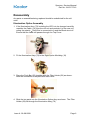
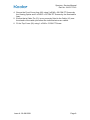
Spectra +
Service Manual
ALWAYS READ THE INSTRUCTIONS
Keeler Limited, Clewer Hill Road, Windsor, Berks, United Kingdom. SL4 4AA.
Tel No. +44 (0) 1 753 857177Fax No. +44 (0) 1 753 830247
Issue A 28-08-2008
Part No 2415-P-7016
Spectra + Service Manual
Part No 2415-P-7016
CONTENTS
Introduction
2
Service Principles
2
Tools Required
3
Precautions
4
Head Unit
5
Disassembly
5
Viewing Optics
5
Illumination Optics Assembly
5
Reassembly
6
Illumination Optics Assembly
6
Viewing Optics Assembly
7
Final Assembly
7
Spare Parts
10
Spare Parts List
11
Issue A 28-08-2008
Spectra + Service Manual
Part No 2415-P-7016
Introduction
This manual covers the repair of the Spectra+ Indirect Ophthalmoscope.
Service Principles
Some parts are only available as assemblies where special tools and
adhesives are used in the manufacturing process.
The remainder of parts are available either individually or as kits of relevant
parts.
.
Issue A 28-08-2008
Page 2
Spectra + Service Manual
Part No 2415-P-7016
Tools Required
Most of the tools required will be in a standard electro-mechanical toolkit.
In addition the following special tools will make the job easier.
TD351
Issue A 28-08-2008
Lockring Key
Page 3
Spectra + Service Manual
Part No 2415-P-7016
Precautions
Care should be taken to carry out any repair work on a clean soft surface to
minimise damage to the outside of the unit and lenses.
Solvents should not be used for cleaning.
Issue A 28-08-2008
Page 4
Spectra + Service Manual
Part No 2415-P-7016
Head Unit
Disassembly
1. Remove 2 off M3 x 20 CSK PT Screws (17) and 2 off M2.5 x 25 CSK PT
Screws (51) holding the Rear Cover (22) to the Front Cover (82)
2. Carefully lift off the Front Cover (82)
3. Lift out the Crank Assy from under the Illumination Barrel Assy. Do not
dismantle the Crank Assy further unless parts need to be replaced.
Viewing Optics
1. Unscrew 2 off Eyepiece Cap (41) from viewing telescopes and carefully
remove 2 off +2D Eye lenses (39)
2. Remove 2 off Eyepiece Lockrings (37) using TD351 Lockring Key
3. Remove 2 off PD Adjuster (73)
4. Remove 2 off M1.7 x 5 Screws (63) holding the Viewing Optics Assy to the
Rear Cover (22)
The Viewing Optics assembly is set up on a laser jig in the factory. Any
further disassembly or adjustment will probably result in misalignment of the
telescopes.
Illumination Optics Assembly
1. Remove 1 off M2 x 4 CSK PT Screw (3) from the Top Cover (66)
2. Slide the Top Cover (66) back along the Cable (16)
3. Carefully unhook the Spring (34) from the Illumination Barrel Assy (81)
4. Remove 2 off M2 x 8 CSK PT Screws (65) and remove the Illumination
Optics Assy.
5. If required the Lemo Plug (15) will just pass through the opening left when
the Top Cover (66) is removed.
Further disassembly of the Illumination Optics Assy should only be carried out
if replacements within the assembly are required.
1. Remove 2 off M2.5 x 12 CSK Screws (49) holding the Left Optics Moulding
(19) to the Right Optics Moulding (18). Take care not to lose the Filter
Detent Ball (71) and Detent Spring (60) as the two parts are parted.
2. The Illumination Barrel Assy (81), Illumination Assy (79), Filter Holder (80)
and Push Bar (52) can now be removed.
Issue A 28-08-2008
Page 5
Spectra + Service Manual
Part No 2415-P-7016
Reassembly
Any parts or assemblies being replaced should be substituted for the old
ones.
Illumination Optics Assembly
1. If the Illumination Assy (79) including the LED is to be changed carefully
unsolder the Cable (16) from the old unit and resolder it to the new unit
noting the polarity Red Wire is connected to A and the Black wire to K
Ensure that the cable still passes through the Top Cover.
2. Fit the Illumination Assy (79) to the Right Optics Moulding (18)
3. Place the Push Bar (52) together with the Filter Holder (58) as shown.
Note the orientation of the parts with each other.
4. Slide the two parts into the Illumination Optics Assy as shown. The Filter
Holder (58) fits through the Illumination Assy (79)
Issue A 28-08-2008
Page 6
Spectra + Service Manual
Part No 2415-P-7016
5. Fit the Detent Ball (71) and Detent Spring (60) as shown.
6. Fit the Left Optics Moulding (19) carefully over the assembly and secure
with 2 off M2.5 x 12 CSK Screws.
7. Fit the LED Heatsink (8) to the Illumination Assy (79) using 1 off M2 x 5
Screw (7). Ensure that there is adequate Heatsink Compound between
the LED Heatsink and the Illumination Assy.
8. Fit the Illumination Optics Assy assembled above using 2 off M2 x 8 CSK
PT Screws to attach it to the Rear Cover (22).
9. Attach the Illumination Barrel Spring (34) to the Rear Cover (22) and
Illumination Barrel (34).
Viewing Optics Assembly
1. Lift the Illumination Barrel Assy (81) and offer the Viewing Optics Assy (78)
to the Rear Cover Assy (22) taking care not to disturb any of the
components mounted on it.
2. Fix the Viewing Optics Assy (78) to the Rear Cover (22) using 2 off
M1.7 x 5 CSK Screws taking care not to disturb the Centre Mirror
assembly on the viewing optics chassis.
3. Ensure that the two telescopes move freely without touching the edges of
the cutouts in the Rear Cover (22)
4. Fit 2 off P D Adjuster (73) over the Viewing Optics telescopes.
5. Fit 2 off Lockrings (37) to retain the P D Adjusters and tighten using TD351
Lockring Key.
6. Fit 2 off +2D Eyelenses (39) to the telescopes ensuring that the curved
surface is towards the user and retain them with 2 off Eyepiece Caps (41)
Final Assembly
1. Lift the Illumination Barrel Assy (81) and fit the Crank Assy
2. Check the Front Cover Assy (82) has 2 off Friction Pads (35) coloured
yellow fitted by the cutouts for the Crank Assy.
3. Lift the Illumination Barrel using the Crank and carefully fit the Front Cover
Assy (82).
Issue A 28-08-2008
Page 7
Spectra + Service Manual
Part No 2415-P-7016
4. Secure the Front Cover Assy (82) using 2 off M3 x 20 CSK PT Screws by
the Viewing Optics and 2 off M2.5 x 25 CSK PT Screws by the Illumination
Assy.
5. Ensure that a Cable Tie (13) is very securely fitted to the Cable (16) over
the sheath of the cable just before the individual wires are visible.
6. Fit the Top Cover (66) using 1 off M2 x 5 CSK PT Screw.
Issue A 28-08-2008
Page 8
Spectra + Service Manual
Part No 2415-P-7016
Issue A 28-08-2008
Page 9
Spectra + Service Manual
Part No 2415-P-7016
Spare Parts
Parts not listed are generally not available as spares.
Missing Item Numbers are part of Spares Assemblies supplied complete.
Parts marked with * or ** are supplied as part of a kit listed at the bottom.
Current prices for spare parts are available from Technical Service.
Technical Service
Keeler Ltd
Clewer Hill Road
Windsor
Berks
SL4 4AA
Phone
+44 (0)1753 827110
Fax
+44 (0)1753 827114
Issue A 28-08-2008
Page 10
Spectra + Service Manual
Part No 2415-P-7016
Spare Parts List
Item Part No
Description
3
SP72-00008
M2 x 4 CSK PT Screw
4
EP79-28988
O Ring
7
SP12-05002
M2 x 5 Screw
8
EP39-16648
LED Heatsink Panel
13
EP79-40899
Cable Tie
14
EP79-11334
Strain Relief
15
EP79-11326
Lemo Plug
16
RP12-06261
Cable
17
SP73-50000
M3 x 20 CSK PT Screw
18
EP39-16875
Rhd Optics Half
19
EP39-16867
Lhd Optics Half
21
EP39-17042
Control Label
22
EP19-01645
Spectra Rear Cover
30
EP39-16736
Rhd Control Knob
31
EP39-16744
Lhd Control Knob
33
EP39-16998
Crank
34
EP39-04292
Spring
35
EP39-38513
Friction Pad
37
EP39-53991
Eyepiece Lockring
39
EP39-53721
+2D Eye lens
41
EP39-53641
Eyepiece Cap
49
SP72-50000
M2.5 x 12 CSK Screw
51
SP72-50003
M2.5 x 25 PT Screw
52
EP39-16891
Push Bar
54
EP39-17026
Base Plate Plug
59
EP39-04399
Leaf Spring
63
SP71-82024
M1.7 x 5 Screw
Issue A 28-08-2008
*
*
*
*
*
*
*
*
*
*
*
**
**
**
*
*
**
*
*
Page 11
Spectra + Service Manual
Part No 2415-P-7016
Item Part No
Description
65
SP72-00001
M2 x 8 CSK PT Screw
66
EP39-70180
Top Cover
71
EP79-30578
Ball
73
EP39-16939
P D Adjuster
77
SP11-65000
Screw
78
1941-P-7022
Viewing Optics Assy
79
1941-P-7057
Illumination Assy
80
1941-P-7030
Filter holder Assy
81
1941-P-7049
Illumination Barrel Assy
82
1941-P-7073
Front Cover Assy
*
**
1941-P-7065
Fixings Kit
1941-P-7081
Viewing optics Extras Kit
Issue A 28-08-2008
*
*
**
*
*
**
Page 12