1
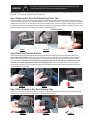
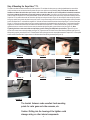
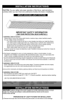
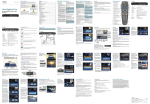
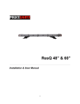
INSTALLATION
& OPERATION
MANUAL
SUPERVISOR™ TL
SuperVisor™ TL
Interior Lighting System
Expedition
2007 Model
CONTENTS:
Introduction .......................................................................... 2
Unpacking & Pre-Installation ................................................ 2
Installation & Mounting ..................................................... 3-4
Wiring Diagram .................................................................... 5
Wiring Instructions & Fusing ................................................ 6
LED Flash Pattern Selection & Troubleshooting .................. 7
Exploded View & Parts List ................................................. 8
Notes .............................................................................. 9-11
Warranty ............................................................................ 1 2
For future reference record your product's serial no. here __________________________________________
Read all instructions and warnings before installing and using.
IMPORTANT: INSTALLER:
This manual must be delivered to the end user of this equipment.
Introduction
The SuperVisor ™ TL is an interior lighting system that fits in the visor area near the top of the windshield. It delivers an amazing warning
signal. The SuperVisor TL is designed on a modular basis, which means that the lightbar can be customized to meet most any
requirements. The SuperVisor TL has room for up to ten LED lightheads. Each lighthead is individually wired for any flash pattern or
combination of flash patterns required.
!
WARNING!
The use of this or any warning device does not ensure that all drivers can or will observe or react to an emergency
warning signal. Never take the right-of-way for granted. It is your responsibility to be sure you can proceed safely
before entering an intersection, driving against traffic, responding at a high rate of speed, or walking on or around
traffic lanes.
The effectiveness of this warning device is highly dependent upon correct mounting and wiring. Read and follow
the manufacturer’s instructions before installing or using this device. The vehicle operator should insure daily that all
features of the device operate correctly. In use, the vehicle operator should insure the projection of the warning
signal is not blocked by vehicle components (i.e.: open trunks or compartment doors), people, vehicles, or other
obstructions.
This equipment is intended for use by authorized personnel only. It is the user’s responsibility to understand and
obey all laws regarding emergency warning devices. The user should check all applicable city, state and federal
laws and regulations.
Code 3, Inc., assumes no liability for any loss resulting from the use of this warning device.
Proper installation is vital to the performance of this warning device and the safe operation of the emergency
vehicle. It is important to recognize that the operator of the emergency vehicle is under psychological and physiological stress caused by the emergency situation. The warning device should be installed in such a manner as to:
A) Not reduce the output performance of the system, B) Place the controls within convenient reach of the operator
so that he can operate the system without losing eye contact with the roadway.
Emergency warning devices often require high electrical voltages and/or currents. Properly protect and use caution
around live electrical connections. Grounding or shorting of electrical connections can cause high current arcing,
which can cause personal injury and/or severe vehicle damage, including fire.
Any electronic device may create or be affected by electronmagnetic interference. After installation of any electronic
device operate all equipment simultaneously to insure that operation is free of interference. Never power emergency warning equipment from the same circuit or share the same grounding circuit with radio communication
equipment.
PROPER INSTALLATION COMBINED WITH OPERATOR TRAINING IN THE PROPER USE OF EMERGENCY
WARNING DEVICES IS ESSENTIAL TO INSURE THE SAFETY OF EMERGENCY PERSONNEL AND THE
PUBLIC.
All devices should be mounted in accordance with the manufacturer's instructions and securely fastened to vehicle
elements of sufficient strength to withstand the forces applied to the device. Driver and/or passenger airbags (SRS)
will affect the way equipment should be mounted. This device should be mounted by permanent installation and
within the zones specified by the vehicle manufacturer, if any. Any device mounted in the deployment area of an air
bag will damage or reduce the effectiveness of the air bag and may damage or dislodge the device. Installer must
be sure that this device, its mounting hardware and electircal supply wiring does not interfere with the air bag or the
SRS wiring or sensors. Mounting the unit inside the vehicle by a method other than permanent installation is not
recommended as unit may become dislodged during swerving, sudden braking or collision. Failure to follow
instructions can result in personal injury.
Unpacking & Pre-installation
Carefully remove the SuperVisor™ TL and place it on a flat surface, taking care not to scratch the lenses or damage the cable coming out of
the side. Examine the unit for transit damage, broken lamps, etc. Report any damage to the carrier and keep the shipping carton.
Standard lightbars are built to operate on 12 volt D.C. negative ground (earth) vehicles. If you have an electrical system other than 12 volt
D.C. negative ground (earth), and have not ordered a specially wired lightbar, contact the factory for instructions.
Test the unit before installation. To test, touch the black wire to the ground (earth) and the other wires to +12 volts D.C., in accordance with
the instructions attached to the cable (an automotive battery is preferable for this test). Some units may be factory wired for control by an
LED flasher in which case the cable's wire tag should be consulted. A battery charger may be used, but please note that some electronic
options (flashers, stingrays, etc.) may not operate normally when powered by a battery charger. If problems occur at this point, contact the
factory.
2
WARNING!
!
Utilizing non-factory supplied screws and/or mounting brackets and/or the improper number
of screws may result in loss of warranty coverage on the equipment.
Mounting Hardware - All mounting hardware is packed in a small box inside the main carton. There are four brackets used to mount the
Supervisor™ TL to the vehicle. These are discussed in detail later.
Step 1-Removing Sun Visor Pivot Brackets and Visor Clips
Begin the installation by removing the driver and passenger sun visors. Remove the three screws that hold the pivot arm bracket of the sun
visors to the headliner using a #15 Torx screwdriver as shown in Figure 1. Remove the single #15 Torx screw that holds the visor clip to the
headliner again using a #15 Torx screwdriver as shown in Figure 2. Carefully reach up above the headliner and pull the visor vanity mirror
light wire free to get access to the harness connecter. Unplug the visor vanity mirror light wire if the vehicle is so equiped by pushing in on the
small square detent (see Figure 3) while pulling on the connector to unplug the harness.
Small Square Detent__ __
__
__
__
__
__
__
>
FIGURE 1
FIGURE 2
FIGURE 3
Step 2 Attach the Pivot Arm Brackets
Attach the outer mounting brackets that are supplied noting the difference between passenger and driver side brackets (see Figure 4
Note:The Driver side is shown). Rotate the pivot arm on the Driver's side sun visor and verify the orientation of the outer bracket as
shown in Figure 5. Replug the Connector that goes to the visor mirror vanity light. Carefully tuck the wire and Connector back into the
hole in the headliner. Note: Make sure the connector is pushed back away from the area where the bracket attaches so thet
you don't crush it when you tighten the screws in the mounting bracket . Position the Driver's side pivot arm and attach the
three torx screws as shown in Figure 6. Repeat this operation for the Passenger side pivot arm and outer mounting bracket. Leave the
torx screws slightly loose at this time.
FIGURE 4
FIGURE 5
FIGURE 6
Step 3 Attach Brackets to Sun Visor Retaining Clips
Place the inner bracket on the retaining clip as shown in Figures 7 and 8. Attach the inner bracket and retaining clip to the headliner with
the torx screw as illustrated in Figure 9. Leave the torx screws slightly loose at this time.
FIGURE 7
FIGURE 8
3
FIGURE 9
Step 4 Mounting the SuperVisor™ TL
The cable can either be routed across the top of the SuperVisor TL and down the door post or up under the headliner at the center of the
vehicle and then across and down behind the plastic door post cover (whichever is preferable). Note: To Route the cable above the
headliner and down behind the door post covers, refer to the service manual for the Ford Expedition for detailed instructions
as to how to remove the door post cover to gain access to route the cable. Once all four sun visor brackets are attached,and the
cable is routed, the SuperVisor TL is ready to be installed. Tilt the rear view mirror down as far out of the way as possible. Carefully move the
SuperVisor TL into position above the rear view mirror by tilting one end up as shown in Figure 10, then swing the other end up into position
being very careful not to scratch the plastic corner post covers. Line up the mounting holes in the outer mounting brackets with the threaded
holes in the SuperVisor TL and thread the supplied 1/4"-20 bolts and internal tooth lock washers into the SuperVisor TL's Outer Panel (see
Figure 11). Line up the mounting holes in the inner mounting brackets with the threaded holes in the SuperVisor TL and loosely thread the
supplied 1/4"-20 bolts and internal tooth lock washers into the holes in the SuperVisor TL's Outer Panel as shown in Figure 12. Carefully
tighten the three torx screws in each of the two outer pivot brackets by tightening each screw a little at a time (see Figure 13). Note:
Tightening the three screws each a little at a time helps prevent cracking the OEM plastic pivot bracket. Tighten the two torx
screws in the center inner mounting brackets (see Figure 14). Tighten the two 1/4-20 bolts in the Outer Mounting Brackets (see Figure 15).
While pushing up firmly on the SuperVisor TL's Outer Panel to close up the gaps as much as possible between the SuperVisor TL's outer panel
and the vehicle's headliner fabric, tighten the two 1/4-20 bolts at the inner mounting brackets (see Figure 16).
FIGURE 10
FIGURE 11
FIGURE 12
FIGURE 13
FIGURE 14
FIGURE 15
FIGURE 16
The bracket fasteners make excellent hard mounting
points for radar guns and video cameras, etc.
Caution: Drilling into the housing of the lightbar could
damage wiring or other internal components.
4
5
Wiring Instructions
!
WARNING!
Larger wires and tight connections will provide longer service life for components. For high current wires it is
highly recommended that terminal blocks or soldered connections be used with shrink tubing to protect the
connections. Do not use insulation displacement connectors (e.g. 3M® Scotchlock type connectors). Route
wiring using grommets and sealant when passing through compartment walls. Minimize the number of splices to
reduce voltage drop. High ambient temperatures (e.g. underhood) will significantly reduce the current carrying
capacity of wires, fuses, and circuit breakers. Use "SXL" type wire in engine compartment. All wiring should
conform to the minimum wire size and other recommendations of the manufacturer and be protected from moving
parts and hot surfaces. Looms, grommets, cable ties, and similar installation hardware should be used to
anchor and protect all wiring. Fuses or circuit breakers should be located as close to the power takeoff points as
possible and properly sized to protect the wiring and devices. Particular attention should be paid to the location
and method of making electrical connections and splices to protect these points from corrosion and loss of
conductivity. Ground terminations should only be made to substantial chassis components, preferably directly to
the vehicle battery. The user should install a fuse sized to approximately 125% of the maximum Amp capacity in
the supply line to protect against short circuits. For example, a 30 Amp fuse should carry a maximum of 24
Amps. DO NOT USE 1/4" DIAMETER GLASS FUSES AS THEY ARE NOT SUITABLE FOR CONTINUOUS
DUTY IN SIZES ABOVE 15 AMPS. Circuit breakers are very sensitive to high temperatures and will "false trip"
when mounted in hot environments or operated close to their capacity.
Route the wiring cable into the passenger compartment down the door post as shown in Figure 17 (passenger side shown) or as
otherwise desired (As stated before in the "Note" in Step 4 the cable can also be routed up above the headliner across and
down behind the plastic corner door post covers and under the dashboard. Refer to the service manual for the Ford
Expedition for detailed instructions as to how to remove the door post cover for access to route the cable). It is advisable to
leave an extra loop of cable when installing the lightbar to allow for future changes or reinstallations. Connect the black lead to a solid
frame ground (earth), preferably, the (-) or ground (earth) side of the battery, and the remaining power wires to the +12V terminal of the
battery, power switches, siren or RLS controller. Each lighthead is wired independently to allow complete flexibility of control.
LED Fusing Considerations
FIGURE 17
Although the average current draw per module is very low, due to the type of circuit used to power each module, the instantaneous
peak current to a module can be significantly higher during low voltage conditions. To avoid prematurely blowing ATO style fuses or
tripping breakers it is recommended the following rule-of-thumb be used to size fuses or breakers. This is especially important in
lightbars with many LED modules running off a single fused source.
Minimum fuse size calculation: (See Wiring Diagram page 5)
For LED 12 volt electrical current only
.5 X (number of 3-LED modules being fused) = Total Electrical Current at 12.8 VDC
Product Features
3-LED Optix lighthead options:
Red, Blue, Amber, White;
Directional, Wide or Hybrid Optics;
Flashing or Steady Burn Control
Size: 50.00" long x 2.01" tall x 6.86" deep
Weight: 7.5 lbs
WARNING!
!
This Product contains high intensity LED devices. To prevent eye damage, DO NOT stare
into light beam at close range.
6
Directional module Flash Pattern - Table 2
CycleFlash (DEFAULT)
NFPA QuadFlash75
Steadyburn
ModelFlash
ActiveFlash
FiveFlash70
QuadFlash70
TripleFlash70
DoubleFlash70
SingleFlash75
Quad Pop Flash75
Triple Pop Flash75
SingleFlash375
SingleFlash250
SingleFlash150
FiveFlash150
QuadFlash150
DoubleFlash150
TripleFlash150
Momentarily short and release
to change patterns
J1
PCB
Flash Pattern Header for OPTIX/LEDX
Troubleshooting
All SuperVisor™ TLs are thoroughly tested prior to shipment. However, should you encounter a problem during installation or during the
life of the product, follow the guide below for information on repair and troubleshooting. Additional information may be obtained from the
factory technical help line at 314-996-2800.
Follow the guide below for information on repair and troubleshooting.
TROUBLESHOOTING GUIDE
Note: LED modules must be replaced as a module. There are no user serviceable parts.
PROBLEM
LED module not
operating when
powered.
QUESTIONS
N/A
POSSIBLE CAUSE
a. Bad power/ground
connection.
b. Defective module.
7
SOLUTION
a. Fix connection.
b. Replace module
Parts List
Reference Number
Part Description
Part Number
1
*LED Module
*Contact Code 3, Inc for P/N
2
Chassis
T14770
3
Outer Panel
T14786
4
Outer Mtg. Brkt. Expedition Pass Side
T14791
5
Inner Mtg. Brkt. Expedition Pass Side
T14779
6
Inner Mtg. Brkt. Expedition Drvr Side
T14780
7
Outer Mtg. Brkt. Expedition Drvr Side
T14792
8
Notes
9
Notes
10
Notes
11
WARRANTY
Code 3, Inc.'s emergency devices are tested and found to be operational at the time of manufacture. Provided they
are installed and operated in accordance with manufacturer's recommendations, Code 3, Inc. guarantees all parts and
components except the lamps to a period of 1 year, LED Lighthead modules to a period of 5 years (unless otherwise
expressed) from the date of purchase or delivery, whichever is later. Units demonstrated to be defective within the warranty
period will be repaired or replaced at the factory service center at no cost.
Use of lamp or other electrical load of a wattage higher than installed or recommended by the factory, or use of
inappropriate or inadequate wiring or circuit protection causes this warranty to become void. Failure or destruction of the
product resulting from abuse or unusual use and/or accidents is not covered by this warranty. Code 3, Inc. shall in no way
be liable for other damages including consequential, indirect or special damages whether loss is due to negligence or breach
of warranty.
CODE 3, INC. MAKES NO OTHER EXPRESS OR IMPLIED WARRANTY INCLUDING, WITHOUT
LIMITATION, WARRANTIES OF FITNESS OR MERCHANTABILITY, WITH RESPECT TO THIS PRODUCT.
PRODUCT RETURNS
If a product must be returned for repair or replacement*, please contact our factory to obtain a Return Goods
Authorization Number (RGA number) before you ship the product to Code 3, Inc. Write the RGA number clearly
on the package near the mailing label. Be sure you use sufficient packing materials to avoid damage to the product
being returned while in transit.
*Code 3, Inc. reserves the right to repair or replace at its discretion. Code 3, Inc. assumes no responsibility or liability for expenses incurred for the removal and /or
reinstallation of products requiring service and/or repair.; nor for the packaging, handling, and shipping: nor for the handling of products returned to sender after the service has been
rendered.
NEED HELP? Call our Technical Assistance HOTLINE - (314) 996-2800
Code 3®, Inc.
10986 N. Warson Road
St. Louis, Missouri 63114-2029—USA
Ph. (314) 426-2700 Fax (314) 426-1337
www.code3pse.com
Revision 1, 07/07 - Instruction Book Part No. T14790
©2007 Public Safety Equipment, Inc. Printed in USA
12